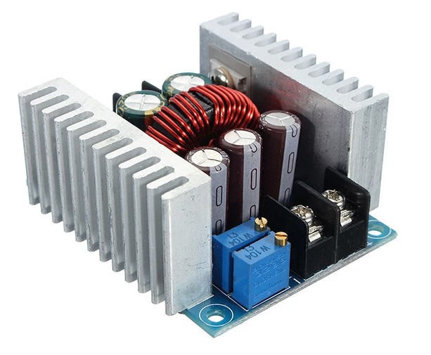
This cheap device follows this schematics (not sure that it is perfect but enough to understand the mod !)
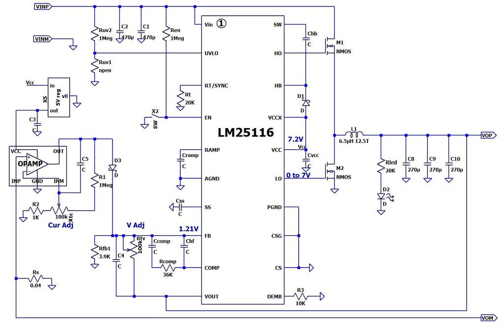
You can control manually the output voltage with the multiturn potentiomer "V Adj". This is producing an offset voltage to the reference 1.21V. This offset is then taken into account by the LM25116 to correct the output Voltage (pin VOUT).
Another (more tricky to understand) voltage offset is issued on top of D3 and added to the Vadj one. This voltage is tuned by the CurAdj potentiometer which is acting on the feedback pin of an Op Amp, the positive pin being directly at the voltage of the shunt resistor Rs (thus proportionnal to current). So this Cur Adj offset is used to limit the current of the buck converter. Interestingly current control and voltage control share the same input on the LM25116 chip. Meaning that the LM25116 is only a voltage controlled device !
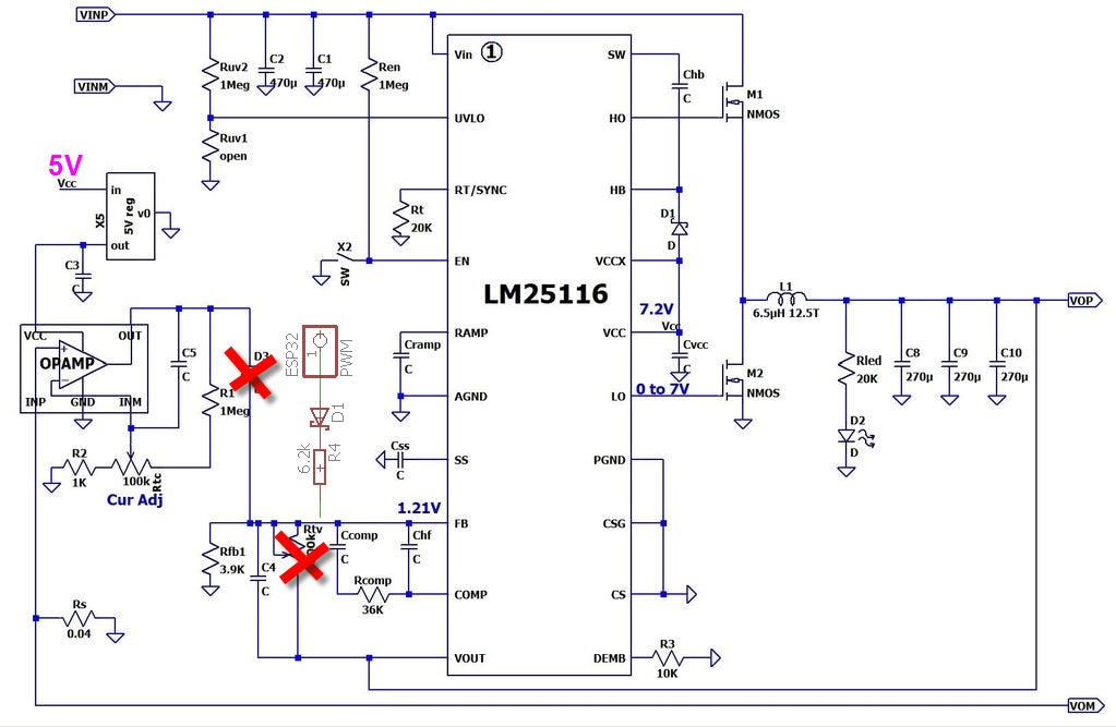
The hack consists in :
- removing the current Adj control (you can do it by desoldering D3)
- removing the V Adj potentiometer
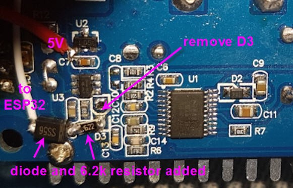
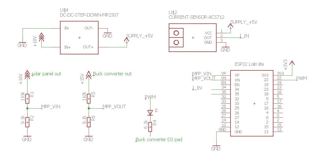
- adding a PWM voltage (seen as a variable DC voltage by the LM25116) in place of D3 and acting as a MCU controlled offset voltage. (So PWM + a 6.2k resistor + a diode)
No need to create a PCB for this... Soldering directly on the back of the Buck convertor is enough (quick and dirty ) !
Similarly you need to measure the PV input voltage and the Buck Output voltage.
These signals will feed the ADC of ESP32.... so we need a voltage divider to bring all this down to max 3.3V...
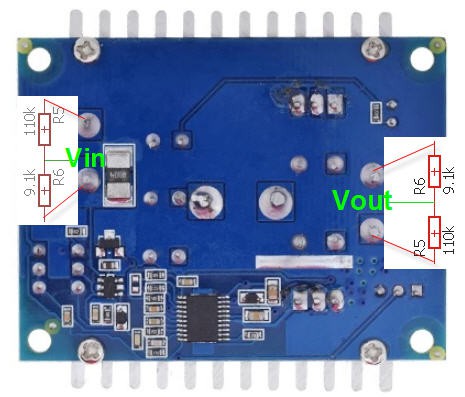
This simple schematics is also directly soldered on the back of the PCB... (quick and very dirty)

Now the only missing signal is the Solar panel Current.
I did try to reuse the Current sense OpAmp of the buck converter but I got more noise than proper signal...
Finally I have invested a few more $ into a AS712 current sensor module. I selected the 20A version which is plenty enough for a solar panel with a 7A max output !
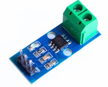
Once again no solder for this module but rather strong copper wires as all the juice is going through it....
This module needs 5V to be powered. Will be shared with the ESP32 5V input
Its output is a voltage between 0 and 5V but with a 0A output at midrange (2.5V). This means , as we only measure DC current, that (if properly wired) the output will only swing from 0 to 2.5V (0 for the max current of 20A). Just to say that there is no need for a voltage divider to accomodate 3.3V...
You will also need a small 360 DC/DC converter to step down the PV input voltage to 5V to power the ESP32 (the small 5V regulator from the Buck converter being to weak to power the ESP32)
And of course you will add another ESP32 lolin32 lite breadboard.
The overall schematics is quite simple : (one day I will do a PCB for this !)
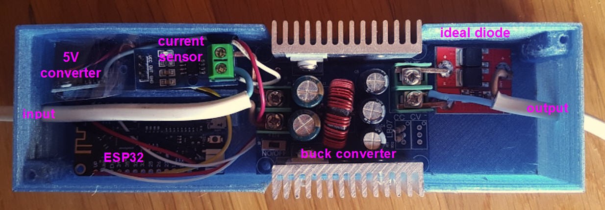
And finally to protect the output battery from reverse flow into the solar panel when no sun, you MUST add a strong Schottky diode on the positive Vout pin. If you have a few $ to spend (I had) then a good choice would be to replace this diode by an ideal diode. It is the red module on the output of the Buck converter picture
The final integration is depicted on this photo.
 JP Gleyzes
Discussions
Become a Hackaday.io Member
Create an account to leave a comment. Already have an account? Log In.
how to fix Compilation error: 'analogSetCycles' was not declared in this scope
//arduino IDE 2.1.0 , ESP32 Wroom
Are you sure? yes | no
Same to me. I used lolin32 lite similar as in this sample
Are you sure? yes | no
Yes they changed the API in latest versions... Simply comment this line and it will ue default values !
Are you sure? yes | no
2 more questions:
- where is going the 3V3 of the esp32?
( Edit: to its own positiv of its alimentation? )
- you take out the potentiometer on the buck converter and replace one part with two resistors of how many kohms?
( Edit: potentiometer baoter 3296 -> 10kohms, so I guess 10kohm resistor should do it )
Are you sure? yes | no
All the answer to your questions are on this page : https://hackaday.io/project/185105-low-cost-solar-panel-solution-mppt-sun-tracker/log/205600-mppt-controller-hardware/
Are you sure? yes | no
and more precisely on this picture : https://cdn.hackaday.io/images/8546091651252573942.jpg
Are you sure? yes | no
Hi! Super project, thank you so much. I'm trying to get all the pieces right. It's not all so clear for me being a beginner.
First question:
Are you plugin the I_IN to both 34 and 35 of ESP32?
If not why are green lines at both 34 and 35 on the schematic?
Thank you!
Are you sure? yes | no
I_IN is going to 34 only as shown on this picture : https://cdn.hackaday.io/images/1931621651302859159.jpg
Are you sure? yes | no