-
Redemption
05/07/2024 at 21:48 • 0 commentsIt's been a while...
The OpenFlap modules have failed me, this (and the birth of my son) caused me to put this project on hold for some time.A good 10 months ago, I ordered supplies for about 30 modules. Once all were assembled and programmed, I started to test them. They did NOT work, not at all. The main issue was that the positioning relied on 6 IR sensors connected to digital inputs, the voltage levels generated by the ir sensor and encoders where not clean enough to rely on a digital input.
So, I decided it was time for a spec bump. The modules have been redesigned to use a Puya py32f003x8 32bit ARM mcu. This mcu allowed me to utilize 6 analog inputs for ir sensors.
I just finished the first new module and everything seems to work! I implemented the main logic and the bootloader, but I still have some work left regarding flashing new firmware using the ESP32 based OpenFlap Controller, implementing various api endpoints, etc...
Another plus, the chip is a bout €0.50 cheaper. Additionally I found similar IR sensors for about €0.90 cheaper. So a €6 reduction in total!
In an effort to resurrect the 30 PIC based modules, I designed an adapter to adapt the PIC footprint to the Puya footprint.
![]()
That's all for now!
-
Major Firmware Rework + virtual trimming
05/31/2022 at 14:12 • 0 commentsSadly, not a lot of sexy new features in this update... I reworked quite some things in the firmware to improve the codebase. I also discovered some bugs and fixed them, the usual... The
One new feature I would like to shed some light on is the virtual trimming.
![]()
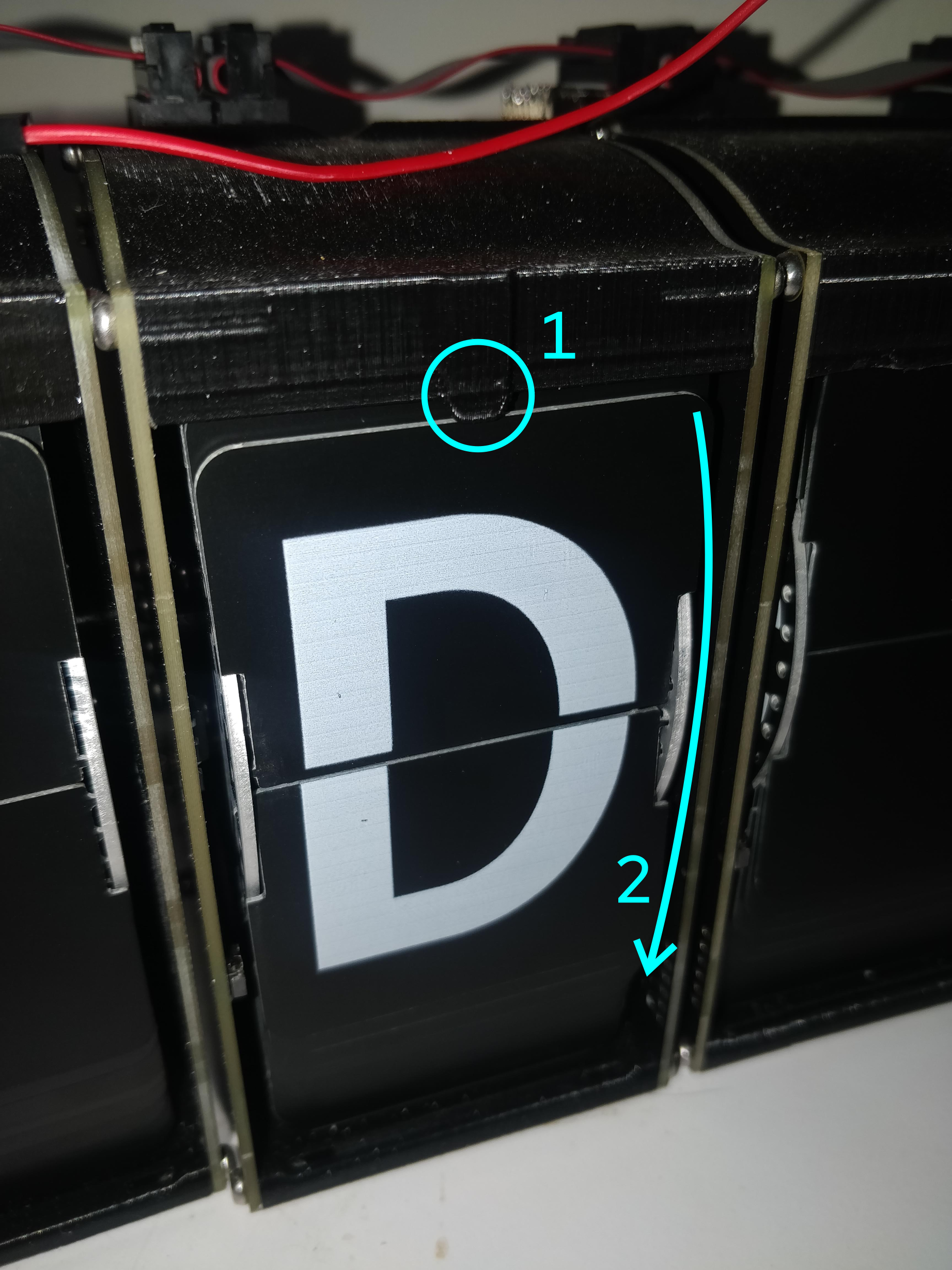
In this picture the letter "E" was requested from the module. The module didn't turn quite enough, to fix this, there are 2 solutions.
Solution 1:
We can physically trim the latch shown in the blue circle marked "1". This will cause the flap to turn over earlier.
Solution 2:
We can have the wheel of characters turn a bit further. This ensures the flap clears the latch and can turn over. Because this has the same effect as trimming the latch, I call this virtual trimming or vtrim.
This setting can be controlled through the webpage and allows up to 128ms delay in increments of 2ms.
-
Controller V1.1 & Top-Con V1.1
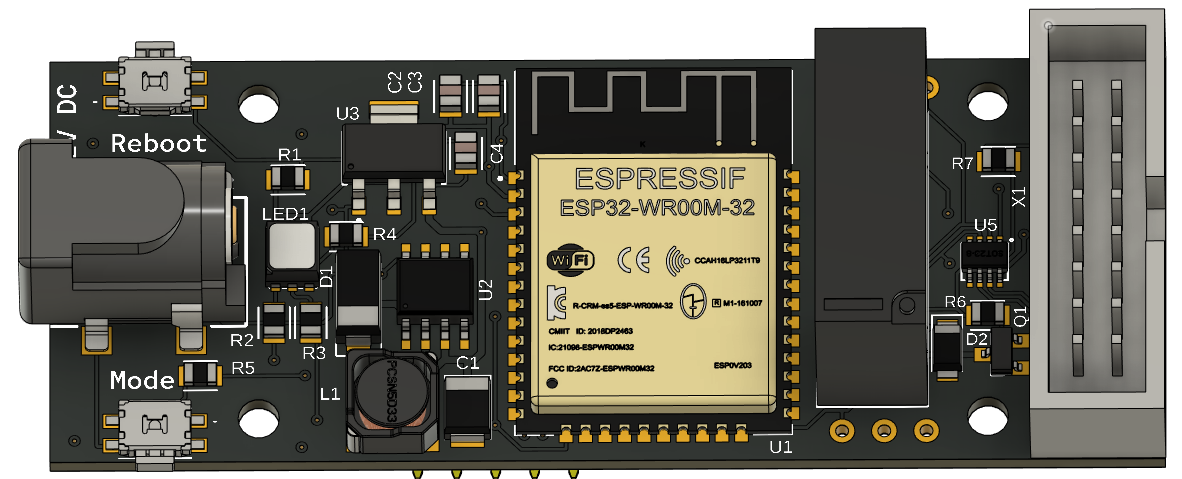
05/12/2022 at 13:36 • 0 commentsThe first controller had some issues which I addressed in this hardware revision.
- The footprint of the logic level shifter (U5) was fixed.
- Added an RGB status LED.
- Added a reset button.
- Added a mode button to select the Wi-Fi mode.
- Changed the right angle box header to a straight box header and changed the orientation 180 degrees.
- Changed the board dimensions to allow for the extra components.
- Changed the relay driver to a mos-fet + diode because of component scarcity.
![]()
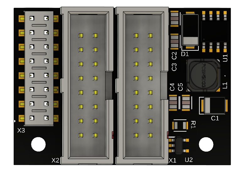
The Top-Con board was updated as well, this was done so all components can be mounted on the same side.
![]()
-
Procedurally generated flaps. Part 2
05/09/2022 at 11:58 • 0 commentsAs noted in the previous part. The Inkscape script wouldn't handle some characters properly. I added an extra step in the character generation process to allow for an easy method to edit the character designs.
The Inkscape script has been spilt into 2 parts "flap generation" and "flap splitting" .
A part of the result of the flap generation is shown below:
![]()
There are some clear issues with the generated characters. Additionally, the width of the "@" character is less than other characters. We can fix all these issues before calling the second part of our script.
The "repaired" character set:
![]()
No we will call the "Flap Split" extension. This will generate the individual .svg files. These individual files can be used as described in the previous part to generate the PCB production files.
-
Procedurally generated flaps.
05/05/2022 at 22:56 • 0 commentsI always knew I would dread creating the design files for all 48 flaps of the display. So I didn't!
Why do something in an afternoon when you can spend 3 days coding a program to do the task!
This is the solution I came up with:
SVG's:
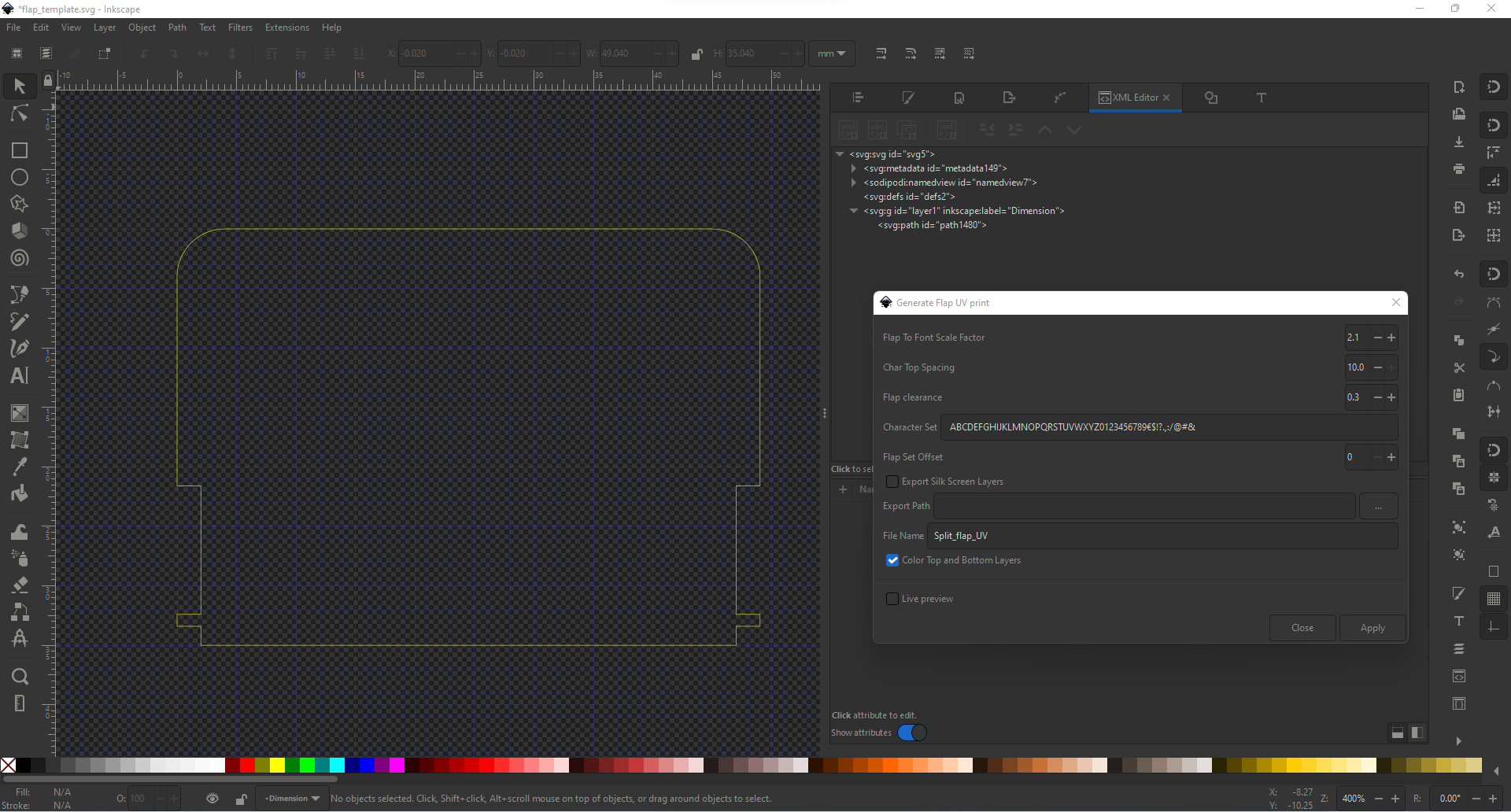
First I created a template file with the flap board-outline on a layer called "Dimension".
I wrote an extension that loops through a list of characters, places them in the svg file, cuts them in half and positions them. Two (half) characters are placed per iteration, each on a separate layer, called tPlace and bPlace. Each flap is separately exported as svg file.
![]()
Eagle .scr:
Now that we have a list of svg files, we need to find a way to import those files into eagle board designs. There is a great tool by Gordon Williams for converting an svg into an eagle scr files. I forked his project to allow me to upload and convert multiple files at once. I also changed his script so the layer used by the eagle script is the same as the label of the Inkscape layer. These changes greatly improved my workflow, though the UI had to suffer...
gerber zip's:
Next I created a batch script that utilises the eagle command line interface to run the eagle scr script and export all the different gerber layers. These gerber files where the combined in a zip file, which can be uploaded to your preferred PCB manufaturer.
The bad news:
The Inkscape extension is not flawless some characters that are not "full height", like: "." and ",", don't play nice with the script and end up in the wrong place. Also depending on the font, some characters have a different weight and look out of place. Those characters must be manually modified.
OpenFlap
The OpenFlap project aims to create a open source, affordable split-flap display for the makers and tinkerers of the world.
 Toon Van Eyck


