 Open Green Energy
-
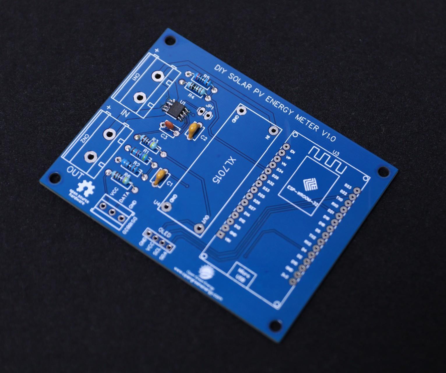
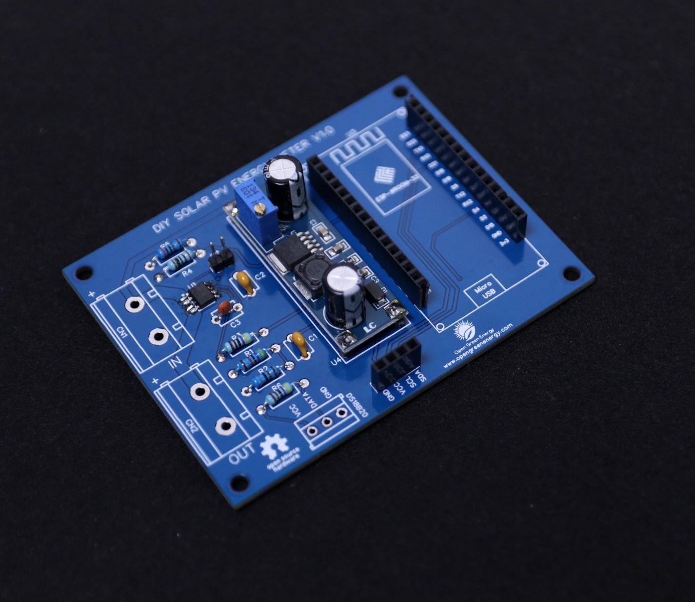
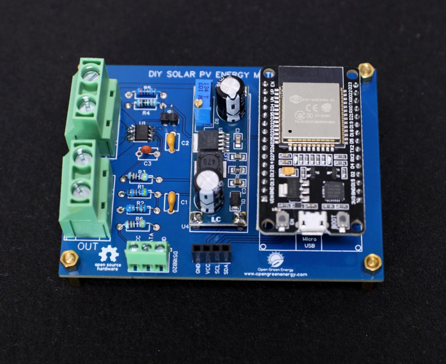
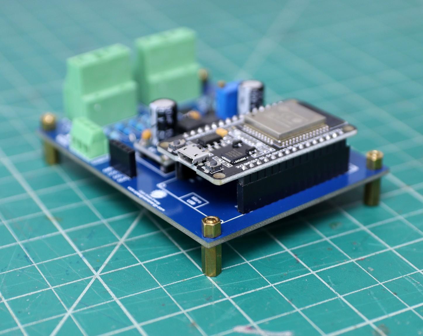
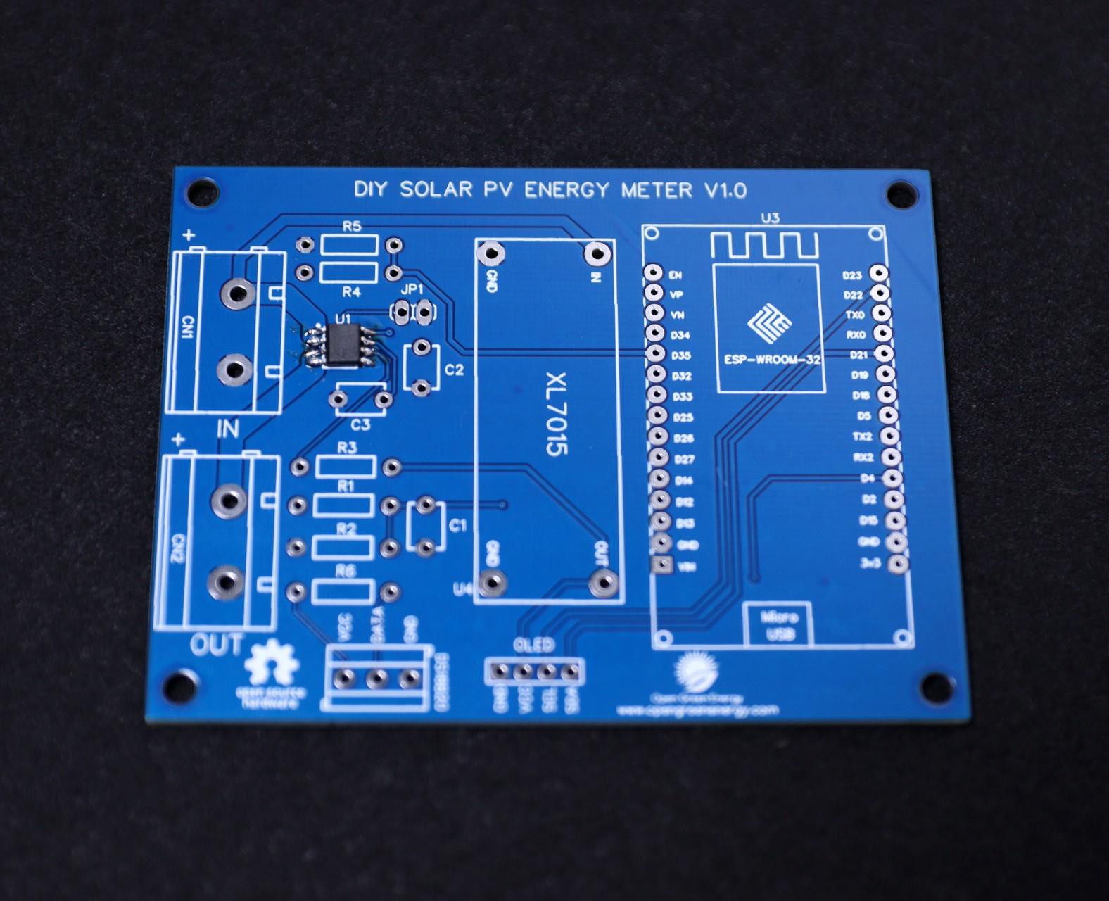
1PCB Assembly
![]()
![]()
![]()
![]()
For Soldering, you will need a decent Soldering Iron, Solder, Nipper, and a multimeter. It is good practice to solder the components according to their height. Solder the lesser height components first.
You can follow the following steps to solder the components :
1. Push the component legs through their holes, and turn the PCB on its back.
2. Hold the tip of the soldering iron to the junction of the pad and the leg of the component.
3. Feed solder into the joint so that it flows all around the lead and covers the pad.
Once it has flowed all around, move the tip away.
-
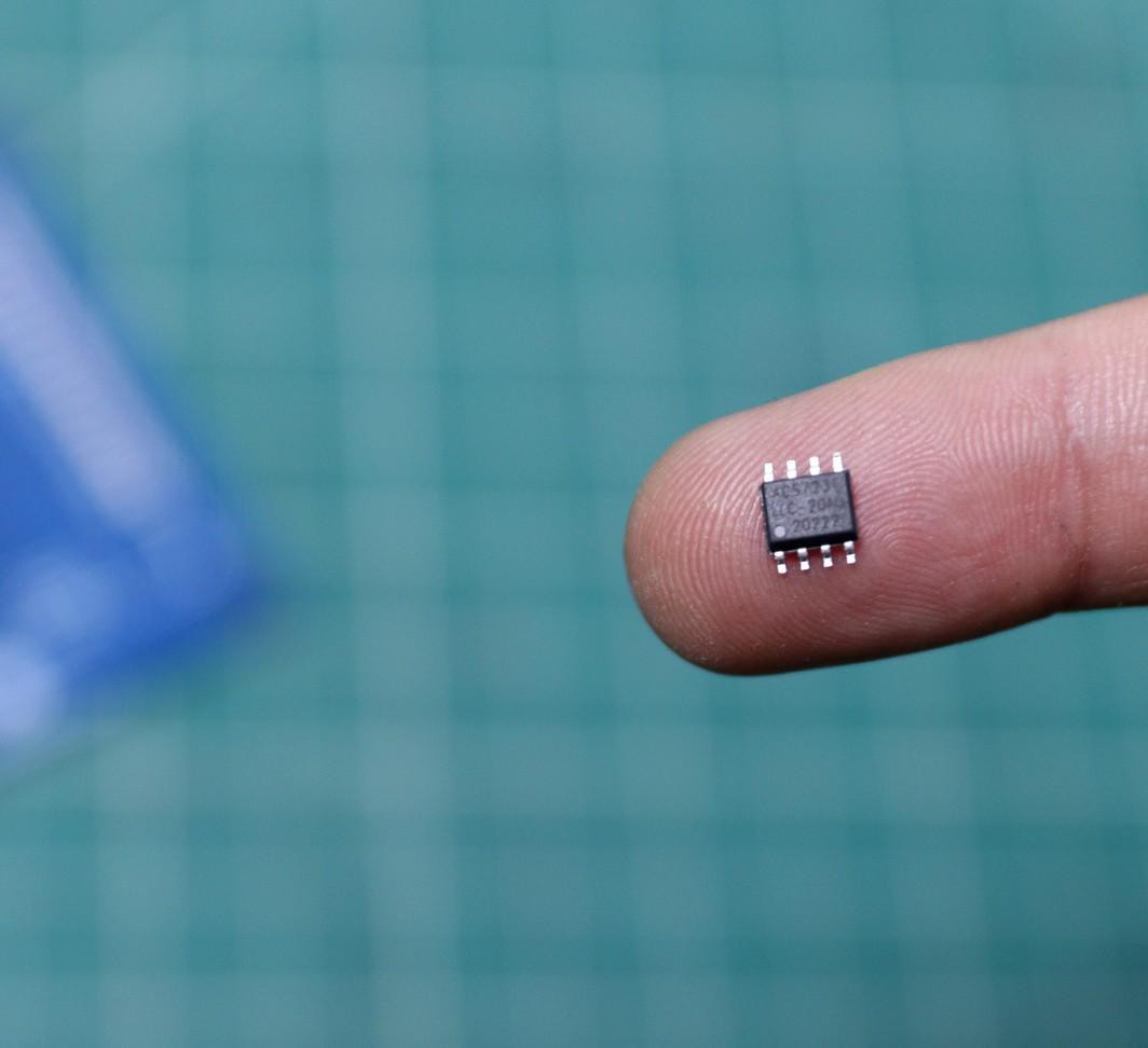
2Soldering the ACS723
![]()
![]()
In the entire PCB, the lesser height component is the current sensor ACS723 which is the only SMT component used in this project.
First, apply soldering flux on all 8 pads, and then apply a small amount of solder to the corner pads. Place and align the diode chip using tweezers. Hold the chip in place while touching the pads with the tip of the soldering iron so that the solder melts the pin and the pad together.
Be sure the dot symbol on the PCB and the ACS723 IC is matching together. The dot symbol represents pin number -1.
Now apply solder to all the pads, and you are done. If you mess up during the soldering, you can remove the extra solder by using a desoldering wick.
You can read this tutorial if you are new to soldering SMD components by using a soldering iron.
-
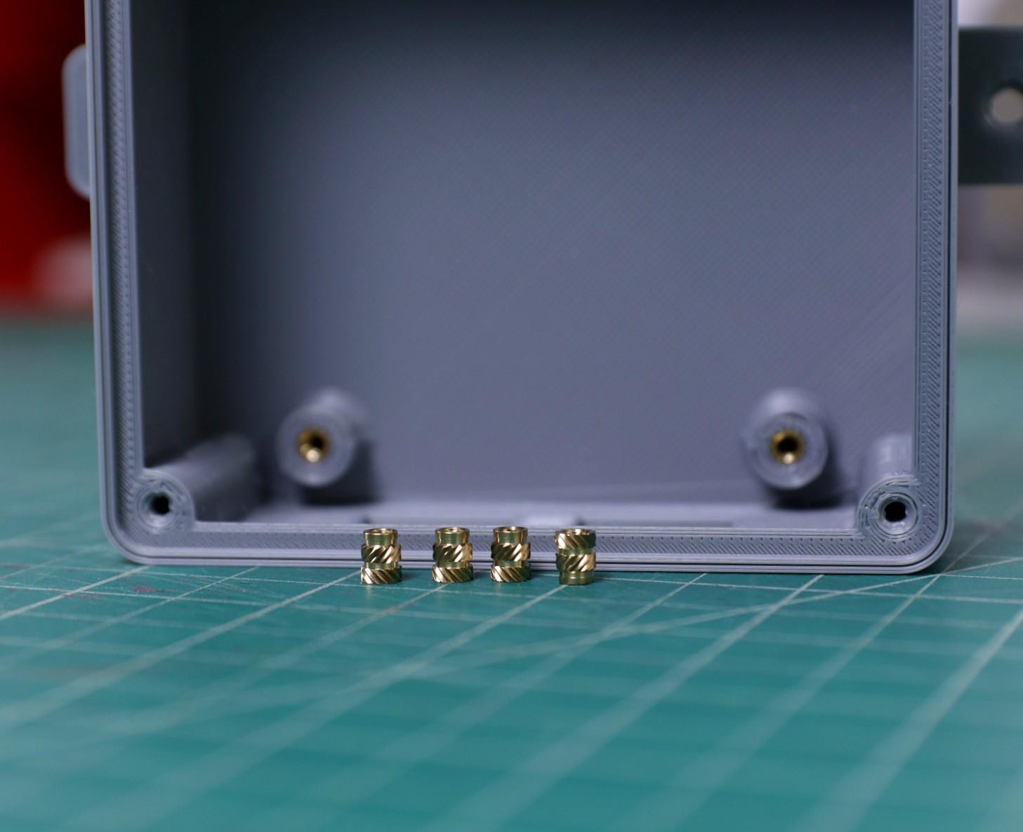
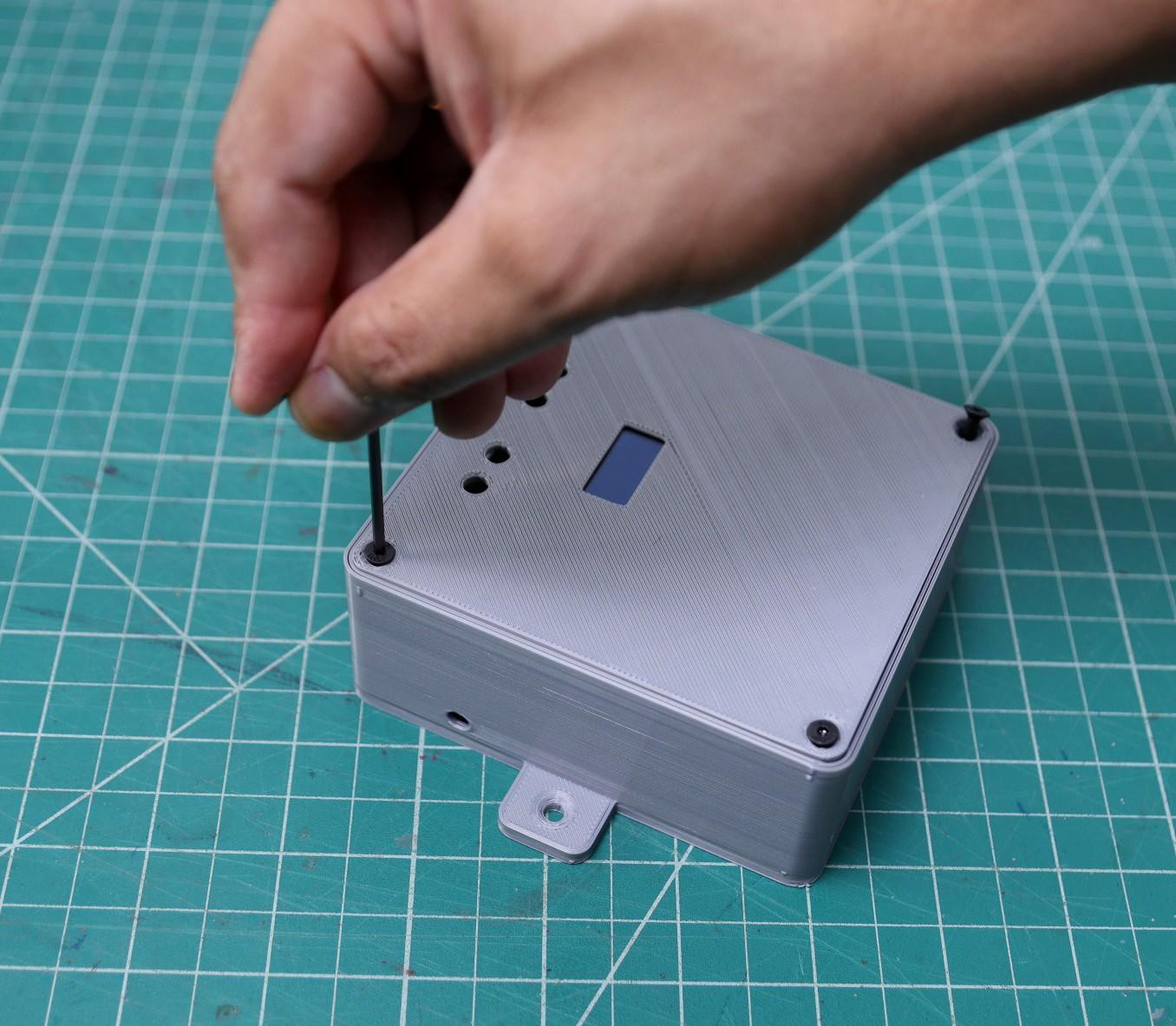
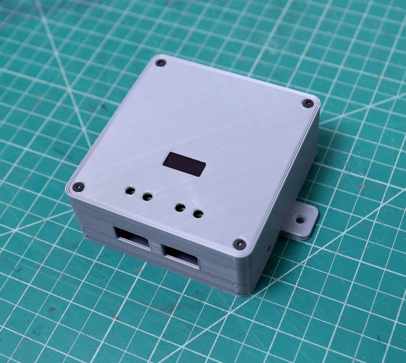
3Assemble the 3D Printed Enclosure
![]()
![]()
![]()
![]()
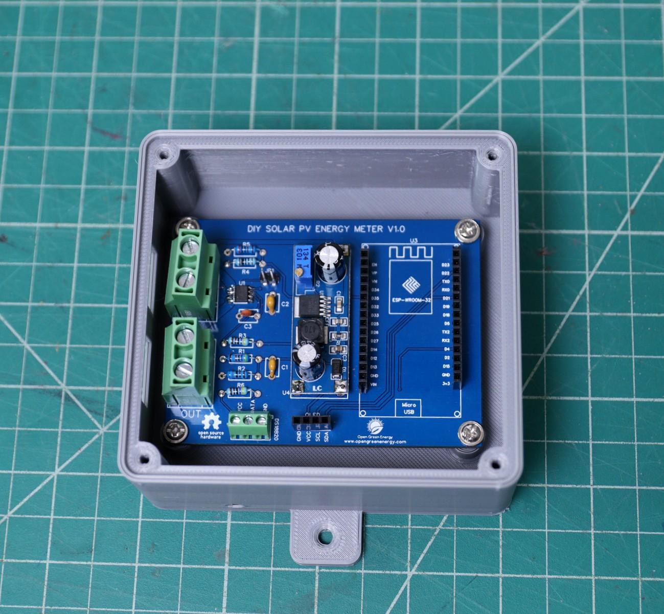
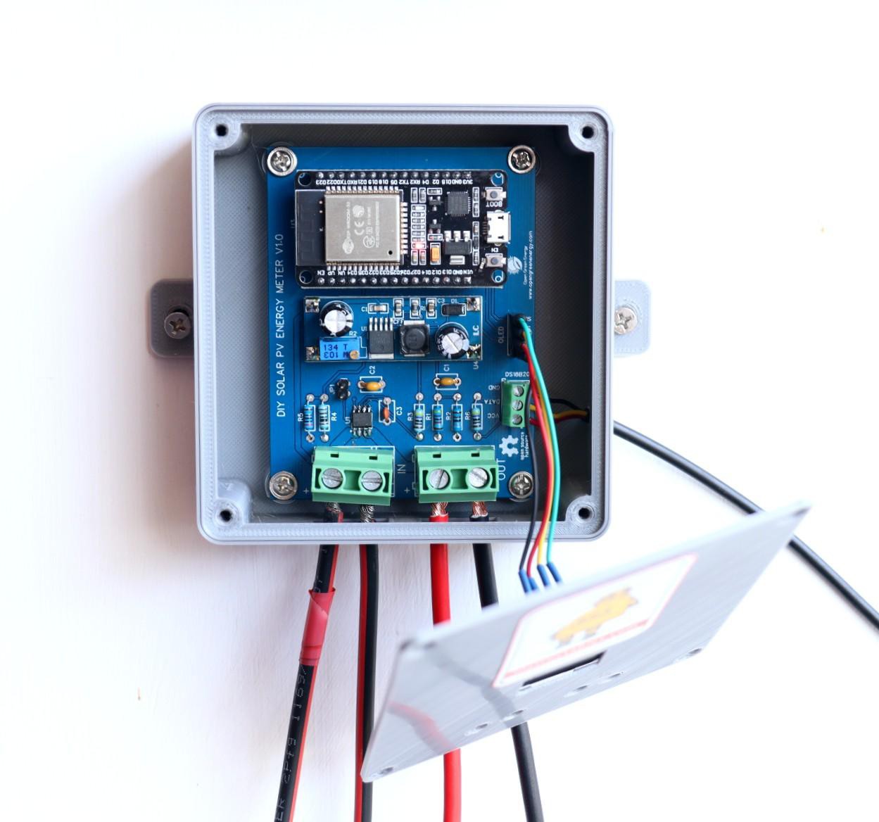
The PCB can be mounted on the 4 standoffs in the 3D printed enclosure. You can directly secure the PCB by using 4 x M3 screws or you may install threaded thermal inserts for more reliability. Here I have used thermal inserts on each standoff.
After mounting the PCB onto the main body, we can move to installing the OLED display. The OLED display can be mounted on the backside of the top lid by using hot glue or strong adhesive tape.
Connect the jumper wires from the OLED display to the PCB OLED port. The header pins on the PCB are clearly labeled.
Insert the temperature sensor cable into the hole given on the right side of the enclosure. Then connect the wires to the screw terminal.
Now close the top lid by using 4 x M3 screws.
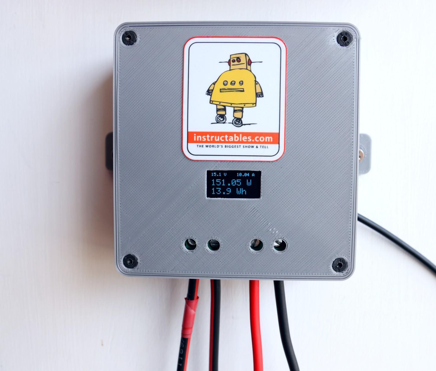
To make the enclosure more attractive, I have stuck an Instructables sticker on the top lid.
-
4Installing Software and Libraries
![]()
![]()
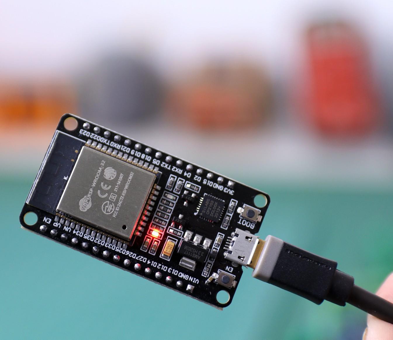
To use the ESP32 board with the Arduino library, you'll have to use the Arduino IDE with ESP32 board support. If you haven't already done that yet, you can easily install ESP32 Board support to your Arduino IDE by following this tutorial by Sparkfun.
Install the Libraries:
Before uploading the code install the following libraries :
1. ESP32
2. Blynk
4. One Wire
How to Install the Libraries?
You can read this tutorial by Sparkfun to install the Arduino libraries.
-
5Interfacing With Blynk App
![]()
![]()
Blynk is the most popular Internet of Things platform for connecting any hardware to the cloud, designing apps to control them, and managing your deployed products at scale. With Blynk Library you can connect over 400 hardware models including ESP8266, ESP32, NodeMCU & Arduino to the Blynk Cloud.
Step-1:
Download the Blynk app
1. For Android
2. For iPhone
Step-2:
Get the Auth Token In order to connect the Blynk App and your hardware, you need an Auth Token.
1. Create a new account in the Blynk App.
2. Press the QR icon on the top menu bar. Create a clone of this Project by scanning the QR code shown above. Once it detected successfully, the whole project will be on your phone immediately. I've made the Sol Weather Station app. You are welcome to try it out!
To start using it:
1. Download Blynk App: http://j.mp/blynk_Androidor http://j.mp/blynk_Android
2. Touch the QR-code icon and point the camera to the code below, enjoy my app!
3. After the project was created, we will send you Auth Token over email.
4. Check your email inbox and find the Auth Token.
Step-3:
Preparing Arduino IDE for Wemos BoardTo upload the Arduino code to Wemos board, you have to follow this Instructables
Step-4:
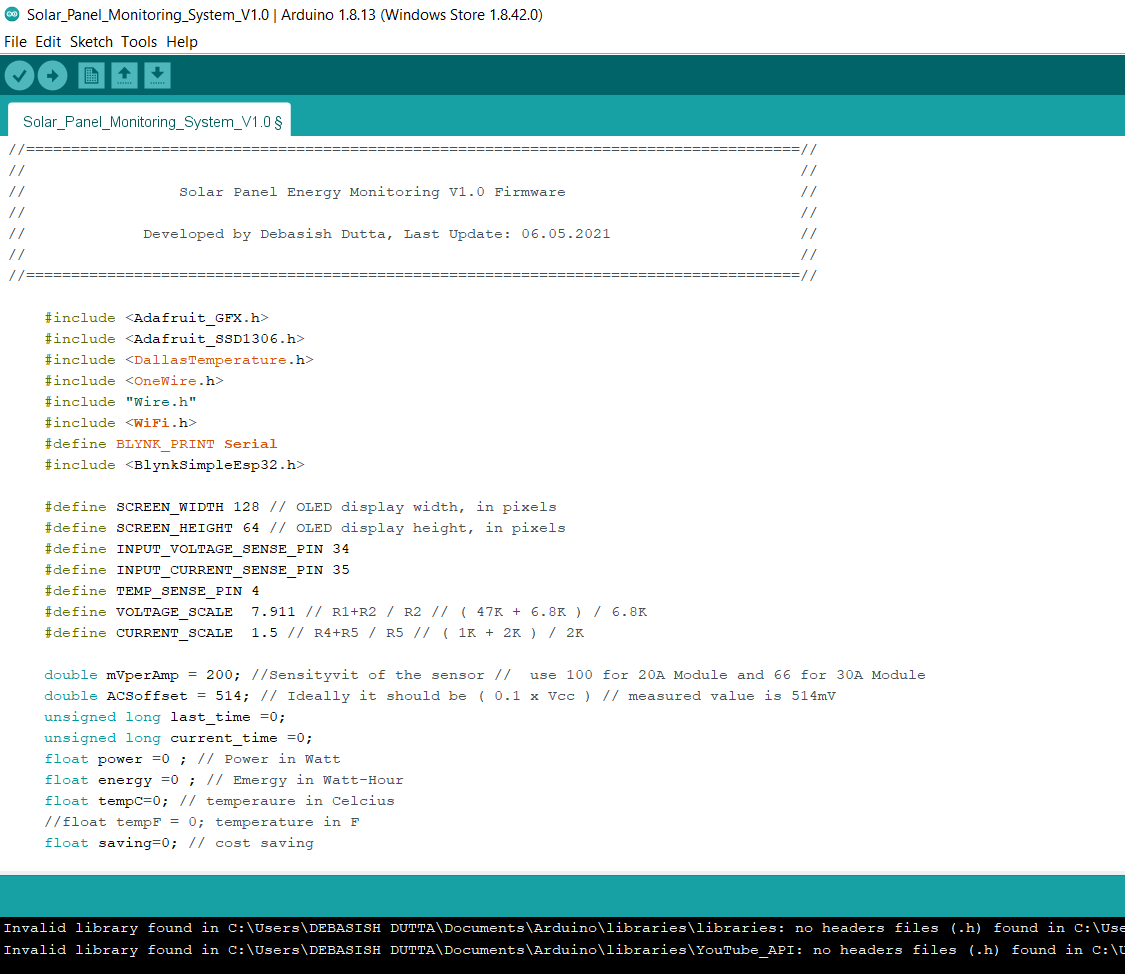
After installing the above libraries, paste the Arduino code given below.
Enter the auth code from step-1,ssid, and password of your router.Then upload the code.
//====================================================================================== // // // Solar Panel Energy Monitoring V1.0 Firmware // // Developed by Debasish Dutta, Last Update: 06.05.2021 // // // //======================================================================================// #include <Adafruit_GFX.h> #include <Adafruit_SSD1306.h> #include <DallasTemperature.h> #include <OneWire.h> #include "Wire.h" #include <WiFi.h> #define BLYNK_PRINT Serial #include <BlynkSimpleEsp32.h> #define SCREEN_WIDTH 128 // OLED display width, in pixels #define SCREEN_HEIGHT 64 // OLED display height, in pixels #define INPUT_VOLTAGE_SENSE_PIN 34 #define INPUT_CURRENT_SENSE_PIN 35 #define TEMP_SENSE_PIN 4 #define VOLTAGE_SCALE 7.911 // R1+R2 / R2 // ( 47K + 6.8K ) / 6.8K #define CURRENT_SCALE 1.5 // R4+R5 / R5 // ( 1K + 2K ) / 2K double mVperAmp = 200; //Sensityvit of the sensor // use 100 for 20A Module and 66 for 30A Module double ACSoffset = 514; // Ideally it should be ( 0.1 x Vcc ) // measured value is 514mV unsigned long last_time =0; unsigned long current_time =0; float power =0 ; // Power in Watt float energy =0 ; // Emergy in Watt-Hour float tempC=0; // temperaure in Celcius //float tempF = 0; temperature in F float saving=0; // cost saving WiFiClient client; // Declaration for an SSD1306 display connected to I2C (SDA, SCL pins) Adafruit_SSD1306 display(SCREEN_WIDTH, SCREEN_HEIGHT, &Wire, -1); // GPIO where the DS18B20 is connected to const int oneWireBus = 2; // Setup a oneWire instance to communicate with any OneWire devices OneWire oneWire(TEMP_SENSE_PIN); DallasTemperature sensors(&oneWire); //========================= Variables for wifi server setup ============================= // Your WiFi credentials. // Set password to "" for open networks. char ssid[] = "XXXX"; // WiFi Router ssid char pass[] = "XXXX"; // WiFi Router password // copy it from the mail received from Blynk char auth[] = "XXXX"; //========================= Setup Function ================================================ void setup() { Serial.begin(115200); Blynk.begin(auth, ssid, pass); sensors.begin(); if (!display.begin(SSD1306_SWITCHCAPVCC, 0x3C)) { Serial.println(F("SSD1306 allocation failed")); for (;;); } display.clearDisplay(); display.setTextColor(WHITE); display.display(); delay(500); } //========================= Loop Function ================================================ void loop() { // read voltage and current float voltage = abs( return_voltage_value(INPUT_VOLTAGE_SENSE_PIN)) ; float current = abs( return_current_value(INPUT_CURRENT_SENSE_PIN)) ; // read temperature from DS18B20 sensors.requestTemperatures(); // get temperatures tempC = sensors.getTempCByIndex(0); //tempF = sensors.getTempFByIndex(0); // Calculate power and energy power = current * voltage ; // calculate power in Watt last_time = current_time; current_time = millis(); energy = energy + power *(( current_time -last_time) /3600000.0) ; // calculate power in Watt-Hour // 1 Hour = 60mins x 60 Secs x 1000 Milli Secs saving = 6.5 * ( energy /1000 ); // 6.5 is cost per kWh // used just for example // ================= Display Data on Serial Monitor ================================================ /* Serial.print("Voltage: "); Serial.println(voltage); Serial.print("Current: "); Serial.println(current); Serial.print("Power: "); Serial.println(power); Serial.print("Energy: "); Serial.println(energy); Serial.print("Temp: "); Serial.println(tempC); Serial.println(voltage); delay(1000); */ // ================= Display Data on OLED Display ================================================ // Display Solar Panel Voltage display.setTextSize(1); display.clearDisplay(); display.setCursor(10, 10); display.print(voltage,1); display.print(" V"); // Display Solar Panel Current display.setCursor(70, 10); if (current >0 && current < 1 ) { display.print(current*1000,0); display.print(" mA"); } else { display.print(current,2); display.print(" A"); } // Display Solar Panel Power in Watt display.setTextSize(2); display.setCursor(10,25); display.print(power); display.print(" W"); // Display Energy Generated by the Solar Panel display.setCursor(10,45); if ( energy >= 1000 ) { display.print(energy/1000,3); display.print(" kWh"); } else { display.print(energy,1); display.print(" Wh"); } display.display(); display.clearDisplay(); // ================= Display Data on Blynk App ================================================ Blynk.run(); Blynk.virtualWrite(0, voltage ); // virtual pin 0 Blynk.virtualWrite(1, current ); // virtual pin 1 Blynk.virtualWrite(2, power); // virtual pin 2 Blynk.virtualWrite(3,energy/1000);// virtual pin 3 Blynk.virtualWrite(4,tempC ); // virtual pin 4 Blynk.virtualWrite(5,saving); // virtual pin 4 //delay(1000); } //========================= Function to Calculate Solar Panel Voltage =================================== double return_voltage_value(int pin_no) { double tmp = 0; double ADCVoltage = 0; double inputVoltage = 0; double avg = 0; for (int i = 0; i < 100; i++) { tmp = tmp + analogRead(pin_no); } avg = tmp / 100; ADCVoltage = ((avg * 3.3) / (4095)) + 0.184 ; // 0.184 is offset adjust by heat and try inputVoltage = ADCVoltage * VOLTAGE_SCALE; return inputVoltage; } //========================= Function to Calculate Solar Panel Current =================================== double return_current_value(int pin_no) { double tmp = 0; double avg = 0; double ADCVoltage = 0; double Amps = 0; for (int z = 0; z < 150; z++) { tmp = tmp + analogRead(pin_no); } avg = tmp / 150; ADCVoltage = ((avg*3331) / 4095); // Gets you mV Amps = ((ADCVoltage * CURRENT_SCALE - ACSoffset ) / mVperAmp); // 1.5 is the scaling for voltage divider return Amps; } -
6Field Testing
![]()
![]()
![]()
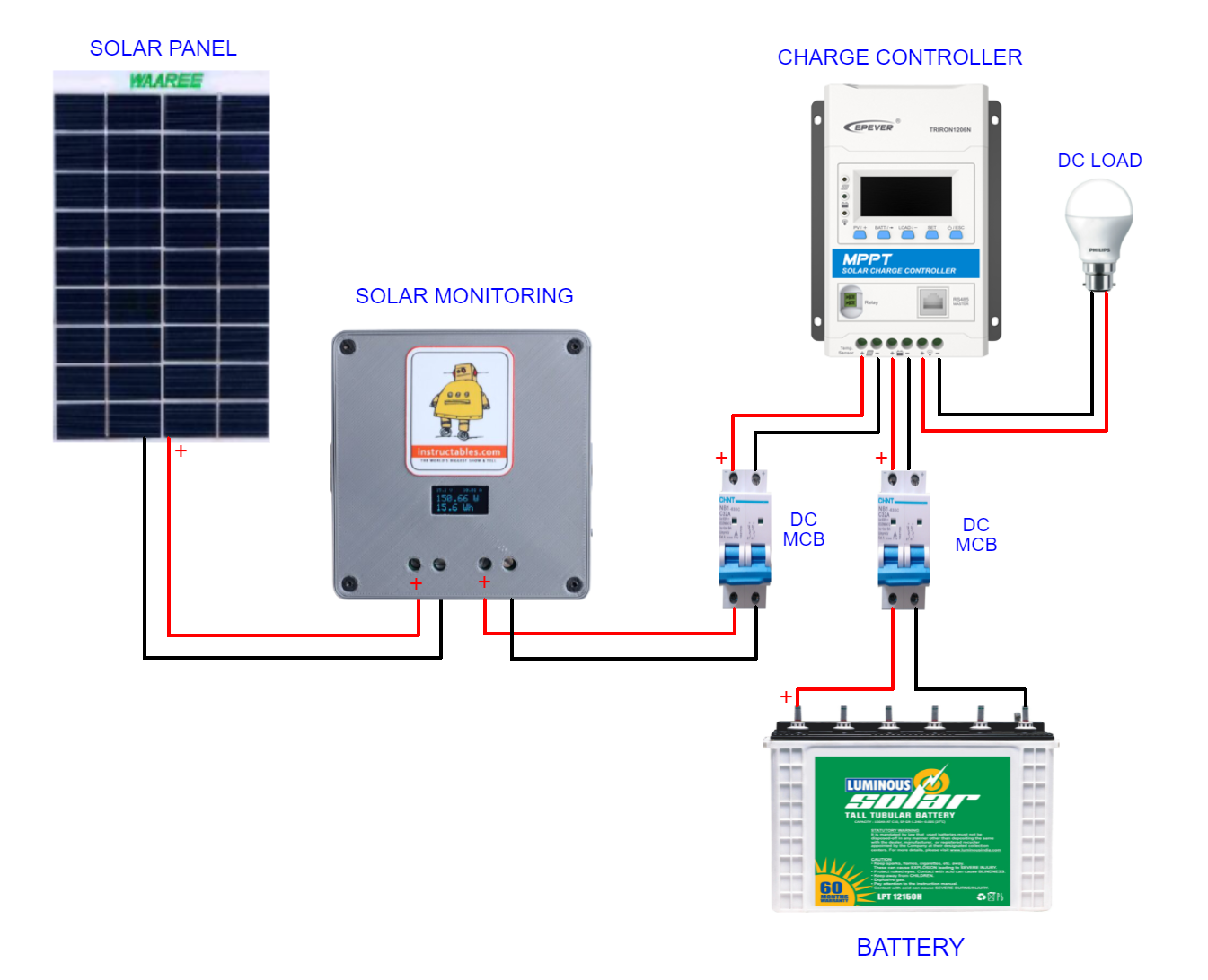
Now our device is ready for real field testing. The connection shall be as follows:
1. Connect the negative terminal of the load to the negative terminal of the output screw terminal and then the positive terminal to the output positive terminal. Here I have connected the out terminal to my charge controller solar input terminal.
2. Connect the Solar panel negative terminal to the negative terminal of the Input screw terminal and positive to the input positive terminal.
The Input and Output screw terminals can be used for wire sizes from 26 - 10AWG.
You can refer to the above wiring diagram for a better understanding.
Note: Be sure you are connecting to the right polarity, otherwise you will see the magic smoke. The circuit doesn't have reverse polarity protection.
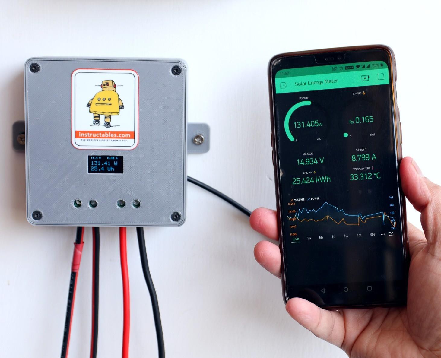
After all the connections, you will see your solar panel parameters displayed on the OLED display. You can check it from your smartphone by opening the Blynk App.
Future Goal: Implementation of MQTT and Home Assistant
Thanks for reading my Instructable.
If you like my project, don't forget to share it. Comments and feedback are always welcome.
DIY Solar Panel Monitoring System
A solar Panel monitoring system with both local and remote display

Discussions
Become a Hackaday.io Member
Create an account to leave a comment. Already have an account? Log In.