 Roddy "Rags" Read
-
1Read up
First off, before building, make sure you have a good clear understanding of what you want to build.
The scale and complexity of a kite turbine project is a large undertaking for a home project.
Check the files section and read the - sub 1kW Kite Turbine Parts Description document to get a clearer idea of what you could build.
I don't recommend going straight to the scale of 1kW - That in itself can be a dangerously powerful kite machine.
Please feel free to adapt this. However-
This project is CC-BY-SA-4.0 as long as you keep it under 1kW.
None of this work is for Kite Turbines in excess of 1kW
We will be attempting automated control of larger Kite turbines at W&I only when we remove all human operations from the field of work.
Thank You for reading that warning list so carefully
-
2Lift kite
Let's start at the top with the lift kite
An HQ KAP foil lift kite is a good steady lifter ... not so strong pulling as a single skin but stable.
Practice with these so you are comfortable with their use before you attach one to a turbine.
Make sure it is pulling >10kg on the line before you attach it to the lift line bearing at the top of the turbine. You are likely to a couple sizes from 3 to 6m.
Here's how they handle in extreme turbulence with a variety of bridle, tether and tail modifications
Making a controller for these lift kites is easy enough with radio control and a servo pulling the B2 steering lines ... This will allow you to pull the turbine to the side and stall it without using a backline.
Adding an arduino and an IMU is bonus - Some simple proportional code https://github.com/rodread/lift-kite-controller
Here's a description of how that went on the AWES forum
https://forum.awesystems.info/t/building-a-rc-pilot-kite/524/18
I used to use 3 lines on the lift kite. The main tether to the turbine head and 2 steering lines to downwind anchors. This however does not let you weathercock the whole set so only do this if your wind is always in a steady direction
Some old Daisy Kite turbine launching videos
-
3Making Kite Turbines 2 different ways
Now for the turbine
First up is the older Ram Air Kite Turbine Way
I published the detail for that on Hackaday a few years back https://hackaday.io/project/159049-portable-kite-turbines/log/149130-oh-yeah-the-kites Gave that hack a big update yesterday
This is how the turbine for the scouts went together
Right now for the 2nd version using rigid blades
... This makes a much faster and more efficient turbine
A single rotor element now looks ~like this
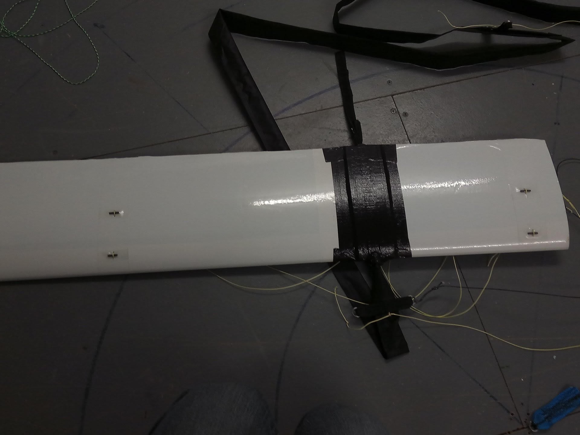
A NACA4412 foil cut from foam, built like a model airplane wing, at 20cm cord ~1m span. Made from 2 parts 1 at 70cm span and one at 30cm pan. The 2 spans are covered in shrink film. The 2 spans plug into the fuselage.
The fuselage joins the blade to the main ring compression cuff. (a tube of dacron tape 340cm long with a web strap at one end and a web strap clamp at the other)
2x 170cm carbon rods go in the main ring compression cuff (forward of the wing)
4 bridles hold the blade to the main tether. Bridles bank the blade with outer tip slightly pointed down (This directs lift away from the axis and helps rotor expansion against torsion.. Helps for stacking rotors.)
An stl of the fuselage is in the github links https://github.com/rodread/DaisyKiteTurbineControl (often appears 10x too small on 3d print slicing software - comes from rhino working in mm not cm)
The 70cm and 30cm span blades are hot wire cut foam, with shrink bonded tape covering. Then plugged into the fuselage cuffs. Then duct taped to the cuffs.
The shrink wrapped blades are slotted into the cuffs of this fuselage .
The spars tubes run through inside the blades and through the fuselage the whole length of the span. The bridles tie around the spars.
A line looped through both of the spar tubes holds them into the foam, preventing them from being flung out by centrifuge. (That has happened. Do avoid throwing spears around your field)
There's 4 wee spreaders (made from ~2cm lengths of rod) to stop the bridles cutting into the wing and spars. A loop on the bridles goes over these bars. The bridles all come out on the other side and tie onto the main tether. Best to set the bridle lengths so that the blades outer tips are closer tot the ground than the inner tips. Helps with aerodynamics and dynamic ring expansion.
![]()
Put 2 of the 170cm rods in the sleeve, attach the sleeve to the next sleeve, repeat until you have (6 in this case) in a rotor.
![]()
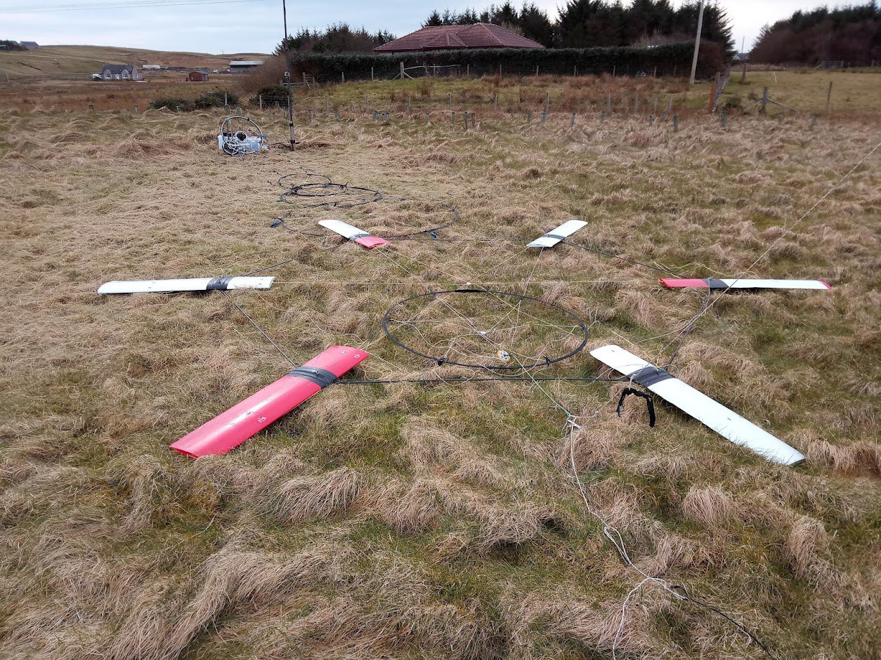
Here is a dimensioning guide for Kite Turbines
For your blade tethers, tension them all with the same weight and mark them to make sure they're all the same length with a figure 8 on the bight tied in the end ready to connect to the tether at the top end of the transmission.
Figure 8 on a bight is easy to turn into a larks head knot to connect over another figure 8 on a bight.
Super simple way to make the system modular. so you can attach new transmission or elements as you like.
For our next set of wings I'm leaning toward ...a mix of cut/print wing rib with foam inserts, a printed fuselage as before, all slotting on together with carbon spars, tied through and end capped ... and also I think a vacuum carbon epoxy skin might work nicely. If you make wings... please get in touch.
Also for getting more blade performance data to the generation control . I've re-worked the amazing D-Rhem VTOL flight controller to get rotational position dat from the rotors with an ESP32 and MPU9250 https://github.com/rodread/dRehmFlight/tree/master/Versions/dRehmKITE_rod_ESP_wifi-mpu9250SPI
-
4The transmission (TRPT)
The stretched out rope ladder part which takes rotational power to the ground
I used these knuckles shapes for a 6 line setup. knuckles as a 3DM or Knuckle outline for water jet cutter Cut them out of hard plastic and use the jig to drill 5mm holes and set and tied 5mm carbon rods into them... This setup isn't ideal as it still allows torsion / twisting in the individual rings... A bar section instead of rod section between the knuckles will be better. Here's an album of how they look
https://photos.app.goo.gl/sD7mVfA6bpjT1v6FA
The basic principles here is - We spin tensioned lines to act like a drive shaft. These lines have to be held apart (away from the axis) by rigid components to transmit torque without torsional compression destroying the shaft.
We tested designs with rods between 2 lines, and rings with 6. In this case we used hexagons made with 6 carbon urethane pulltruded rods set into the knuckles. The hexagonal node knuckles are stitched to the tether lines at even distances. (pre stretch and mark your tether lines carefully and add small dacron tabs to make stitching the nodes to the tethers easier and strong).
Each hexagons is also compressed with a lightweight single line wound around every rod and around the whole perimeter.
Some simulation and modelling on YouTube
-
5Several ways to go about making a Ground Station
Taking Power from the sky on the ground
Before writing this updated project for the hackaday prize I rewrote a lot of detail on my old post https://hackaday.io/project/159049-portable-kite-turbines Some of the project logs there have neat data on ground stations.
Basics
Something in the sky is spinning a set of tight lines - we need to turn a generator.
You just need an anchor, a wheel and a brake to prove mechanical operation. See the last video in this instruction for a lightweight flying version.
We can use the lightweight transmission torque to turn a wheel near ground level.
The ground wheel (PTO Power Take Off Wheel) should align axis with the transmission axis for stable transmission. That's not always easy despite the transmission having a lot of tension and being attached to the rim of the PTO, it can also be quite dynamic in operation and move the PTO around laterally if it's not held well by a ground station.
The PTO is also resisting torque from the transmission because it is connected to and driving a generator. So the PTO is forcing the transmission to deform into a more spiral shape. But don't worry too much about that, just limit the amount of torque and it'll run fine.
I said, You just need an anchor, a wheel and a brake to prove mechanical operation. But then you'll want to improve on that and want tracking, tension sensing, driving and control of the regen... Some ideas and plans of Ground Stations I've made https://github.com/rodread/GroundStation
VESC is a great motor / regen controller Some of our github data https://github.com/rodread
This video gives you the grand tour of the last ground station <1kW
You can get away with making a lot less of a Ground Station
In fact all you really need for a ground station is a stick in the ground and a wheel
OK, if you're really going for portable points... You don't even need a ground station...
You just need a valley
A very rough concept of a mini but powerful and more automated ground station we might attempt soon.
Just above the blue hub, you can see an azimuth drive motor on the left... That will keep the topside more steady and maybe be used to drive the anchor into the ground. The regen motor shown there is likely way too big. unless this is a >40kW model and depending on the gearbox ratio and the kites flown....
There is a lot of scope for adding and extending sensing control and automation to the ground station. Line tension, speed data, alignment data, rotational lag, anchor data... I'm working on it. you can too.
-
6Watch some overview vids to make sure you know what you're doing
Watch this Hackaday how to vid
-
7Wonder if you can make it more simple
The best part is the part which isnt there (Or something like that is being attributed to Elon Musk)
well ok
let's get rid of all those lines... The following vid only has a 1 TRPT line experiment.
Can you make a more simple transmission than this one?
Food for thought
Are there easier ways to make the blades - surely they could be squirted out of an extrusion machine, or foam moulded like toy aircraft and sent into the sky in their thousands.
There must be an easier way to control a lifter and it's launch / recovery.
-
8Wonder if you can make it more complex
The best lines are the network lines
Probably someone on the internet said that
How big can you make a kite turbine network of networks?
The reason for network lines is they can break - and the whole system can continue to work.
You can see plenty of our breaking line "experiments" / opportunities for learning on the youtube.
Complexity is going to help in the control of the generation dynamic. by monitoring line tensions, head positions, relative rotation of the rotor and Power Take Off wheel - we'll be able to keep the transmission smooth and safe.
-
9Wonder how efficient this is
That's a weird dynamic kite turbines have
Yes it is - I'd advise asking Ollie, He did the PhD on it.
Also worth considering how much they capture or block the frontal flow...
You can likely do a lot better job than me on modelling this
If you put anemometers on the field and power meters in the drive train you can get data back into the rhino grasshopper mix which looks like
The files are all on the AWES forum https://forum.awesystems.info/
-
10please share your results
You've probably realised I'm keen on kite turbines
because of the cheap, clean, scalable, low carbon energy potential.
So please for the love of the wee man please if you build one
Let us know how it goes.
Maybe share the design in any of the forums mentioned above or on mastodon
thanks
And ask me if you want any help
As a reminder of why
Energy Independence While Travelling
Bring your own clean power. Pack a Kite Turbine in your EV
Discussions
Become a Hackaday.io Member
Create an account to leave a comment. Already have an account? Log In.