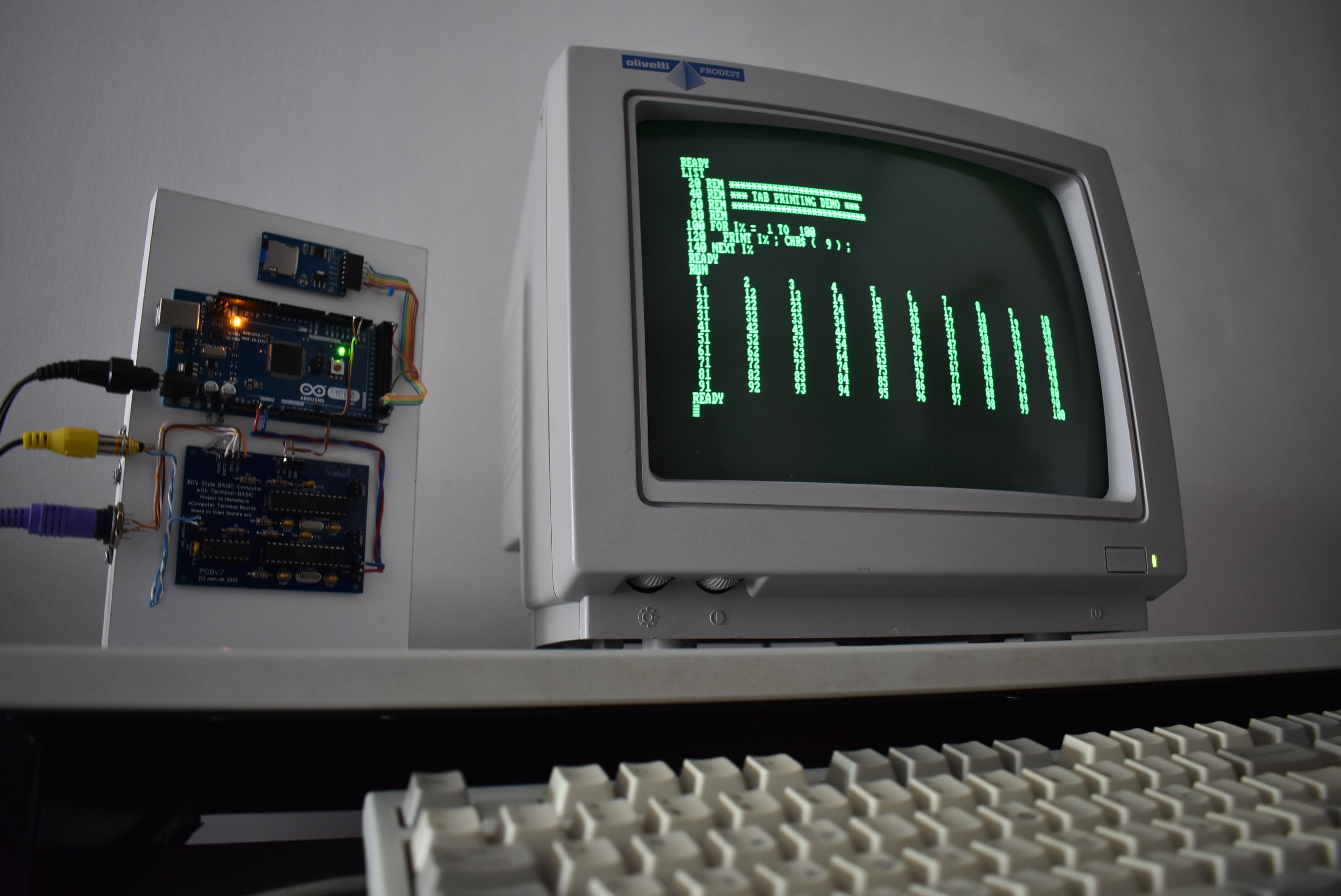
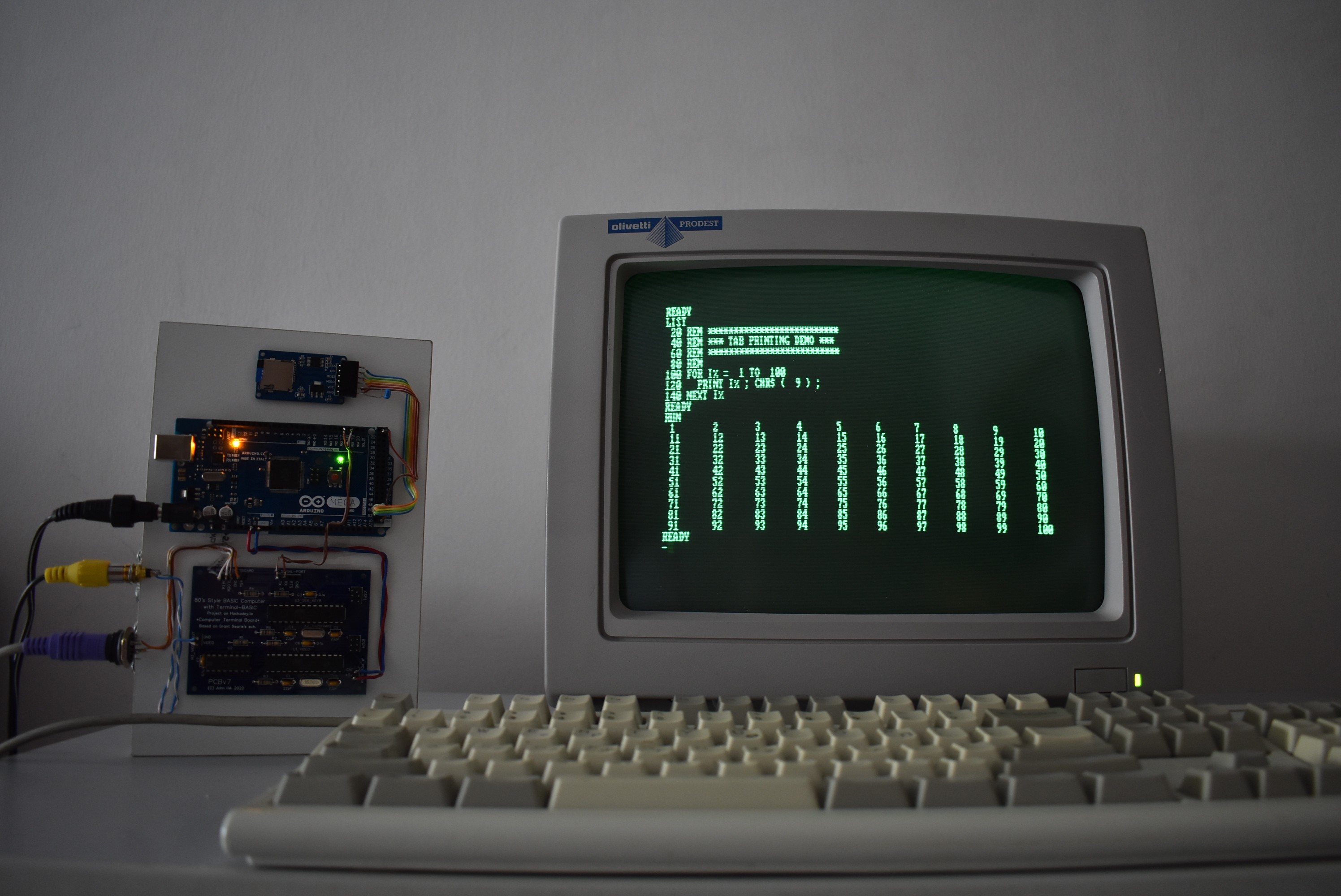
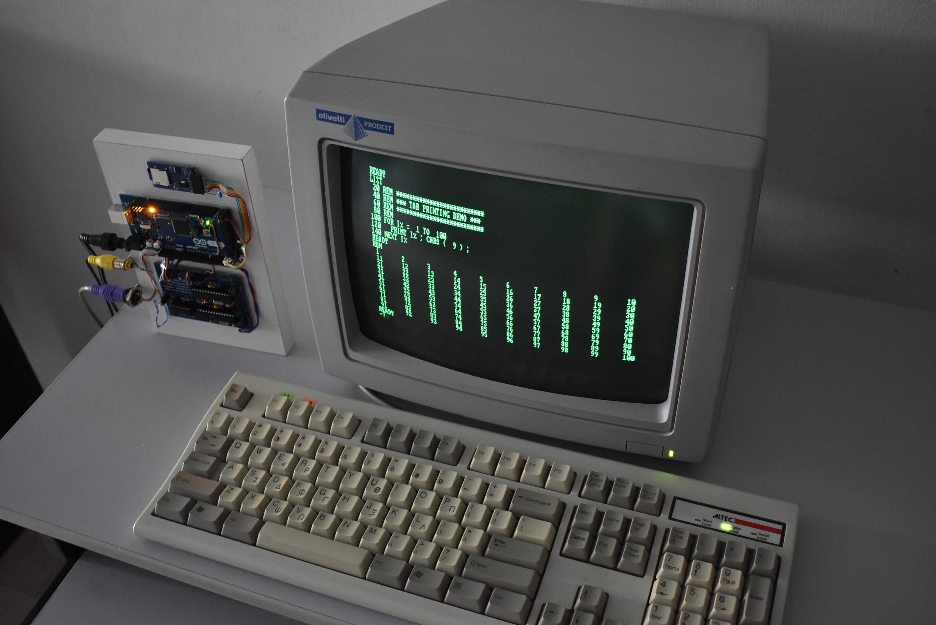
I also tested the completed computer on an Olivetti monitor (that I own), and also a different PS/2 keyboard. Results were equally satisfying. I have to say I enjoy using the "Terminal-BASIC" programming language (by Andrey Skvortsov) which is the initial reason I put together the whole project of the "BASIC Computer"; it's user-friendly and quite versatile in its features.
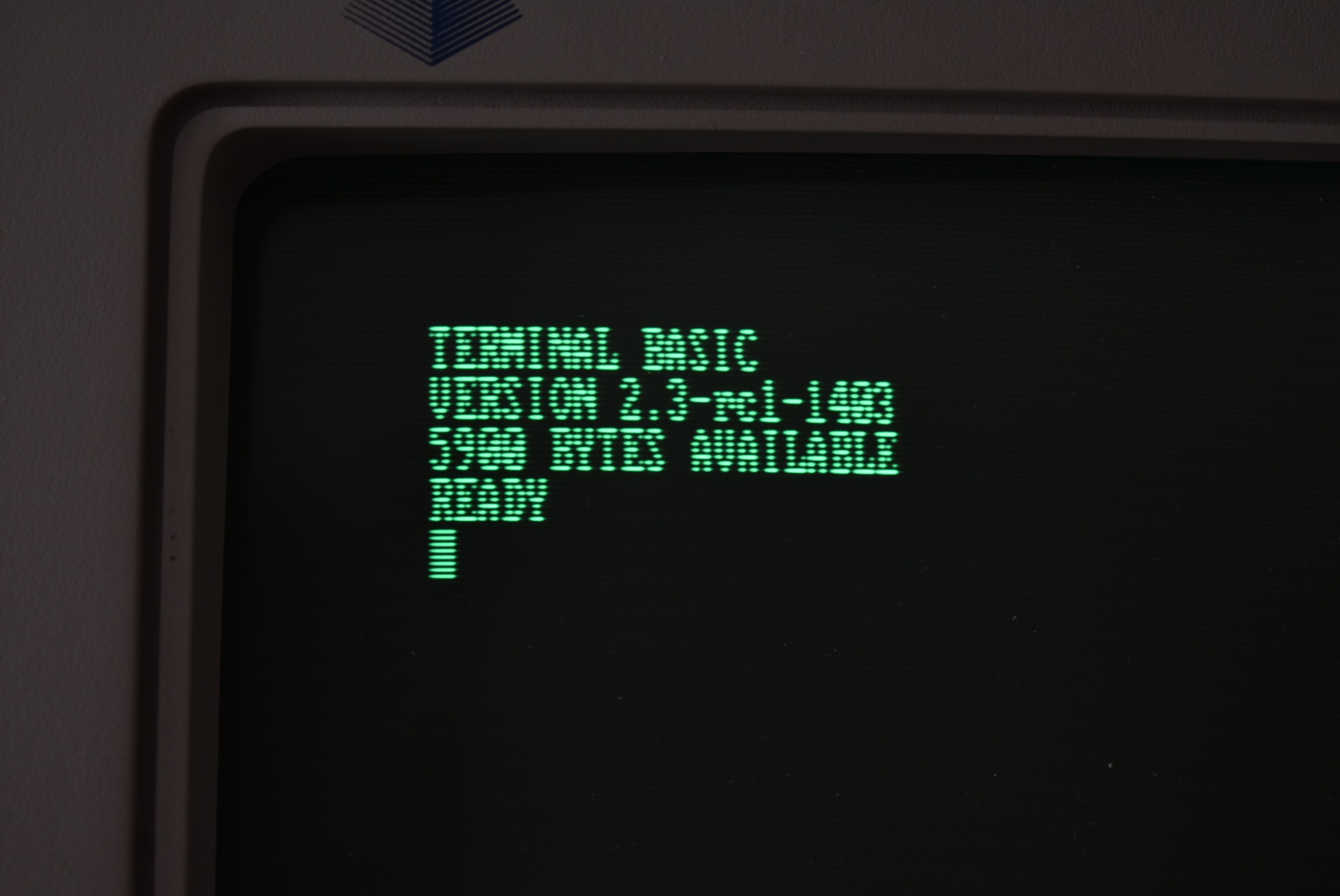
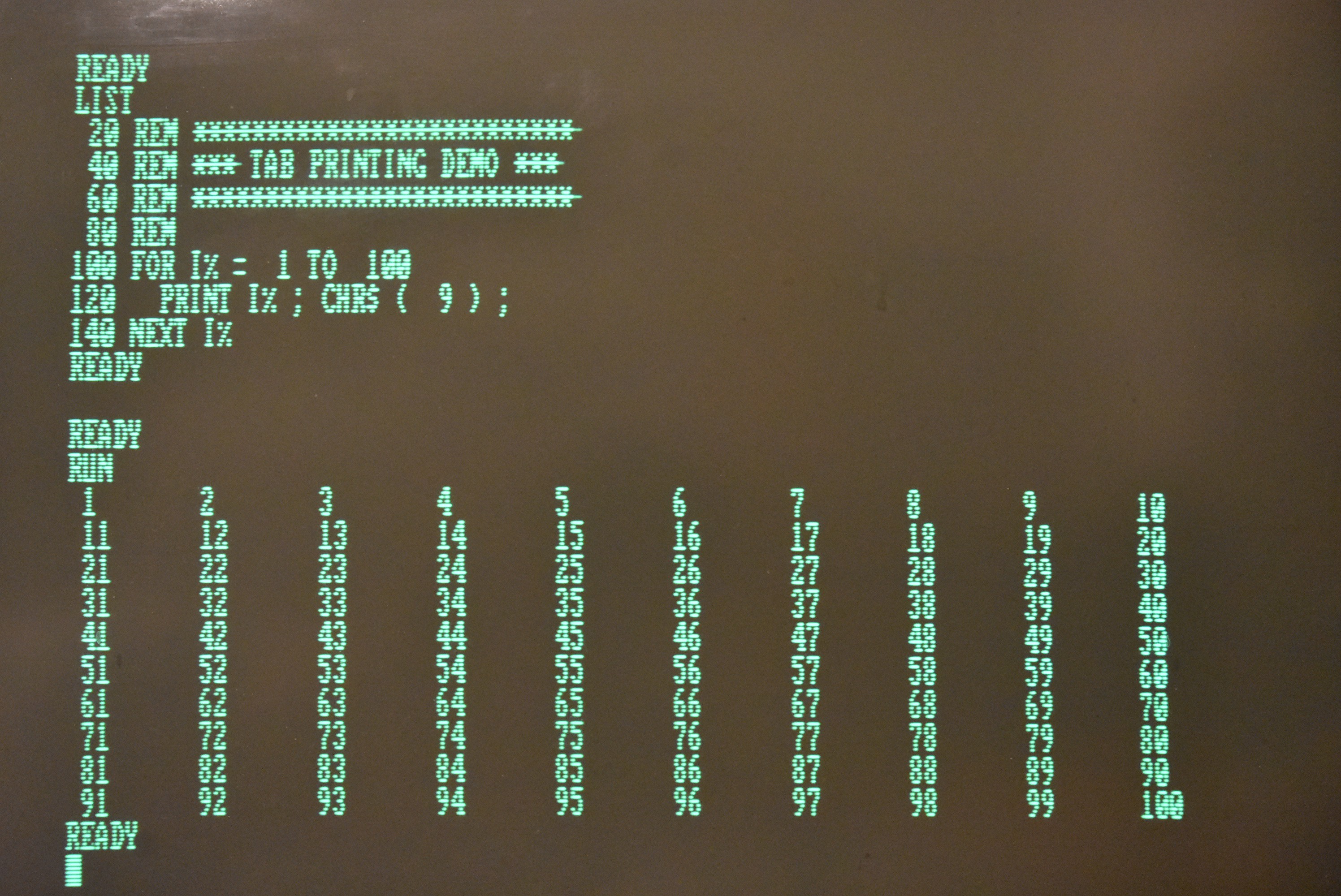
The Terminal-BASIC startup message greets you when you boot up the machine:
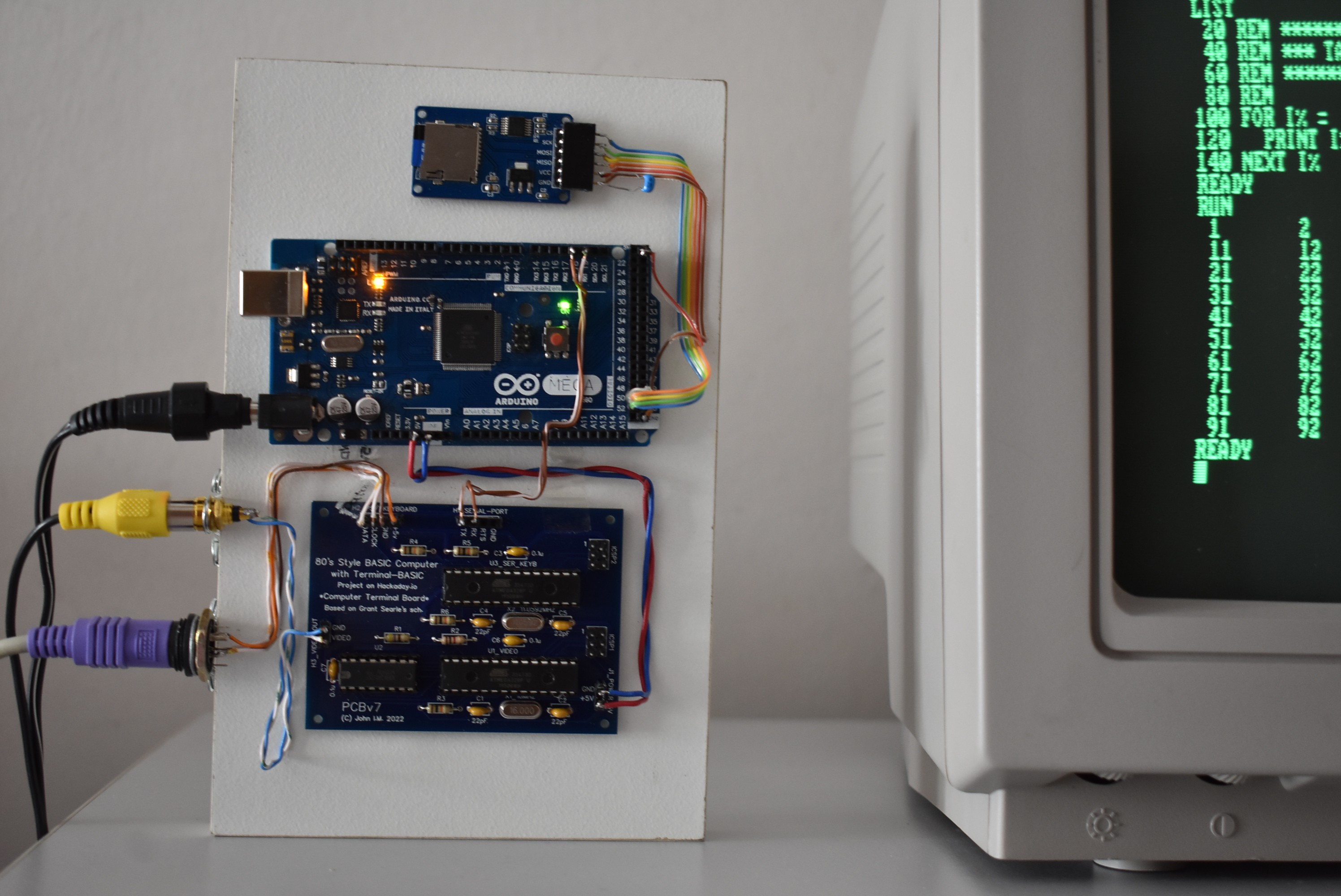
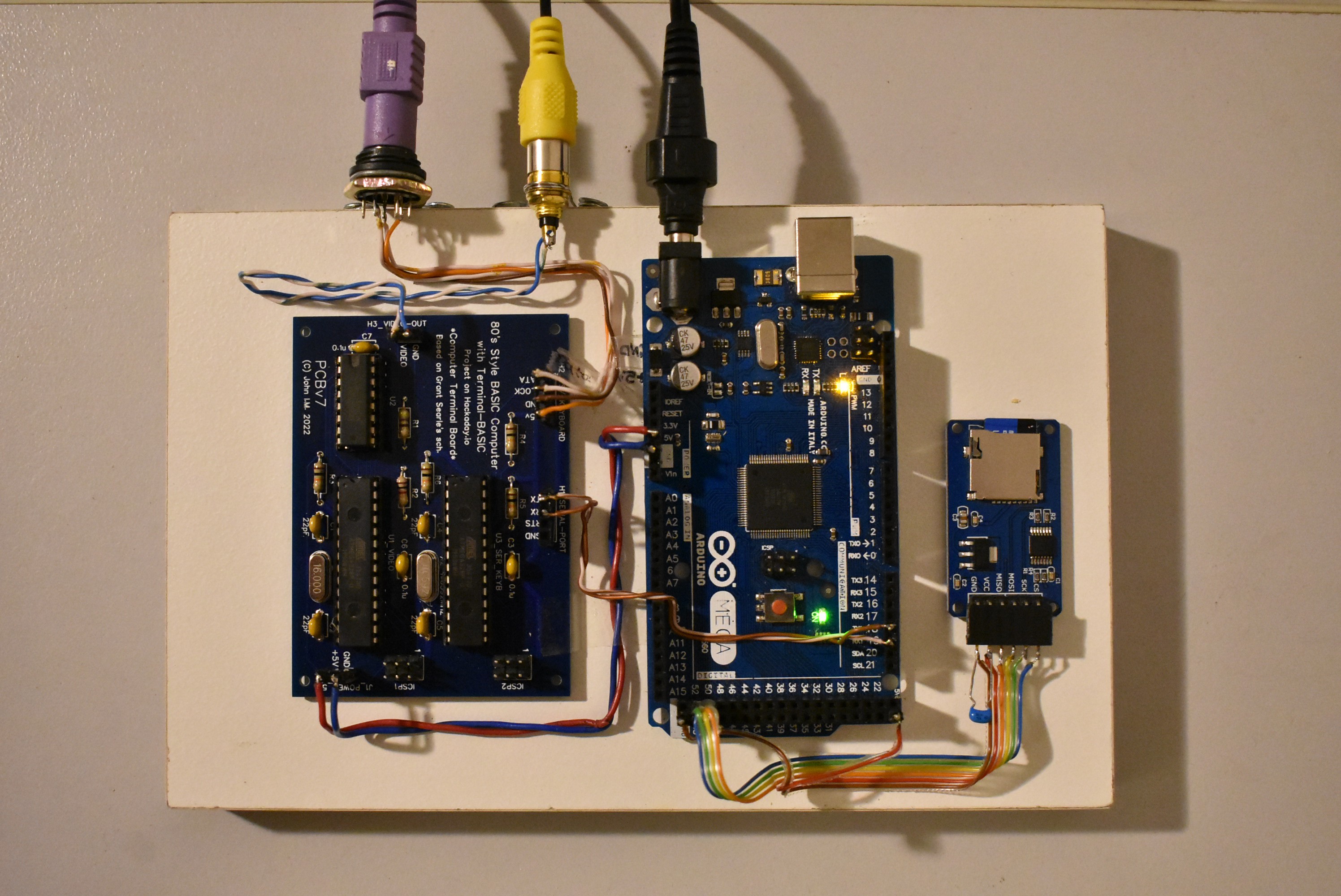
The total hardware of this computer is really minimal: just 3 boards. The only board that needs to be assembled is the "Computer Terminal Board" (lower one of the three). The other two are out-of-the-shelf parts: microSD-Card module and Arduino MEGA2560 .
More details on programming the chips for the "Computer Terminal Board" and assembling the board later. For now, just take a look at the pictures and feel some magic of the 80's ! :-)
I started assembly of the board as soon as I had some free time: the next day after delivery. The necessary electronic parts are common and, anyhow, I already had those from the breadboard prototype, which was dismantled to bits.
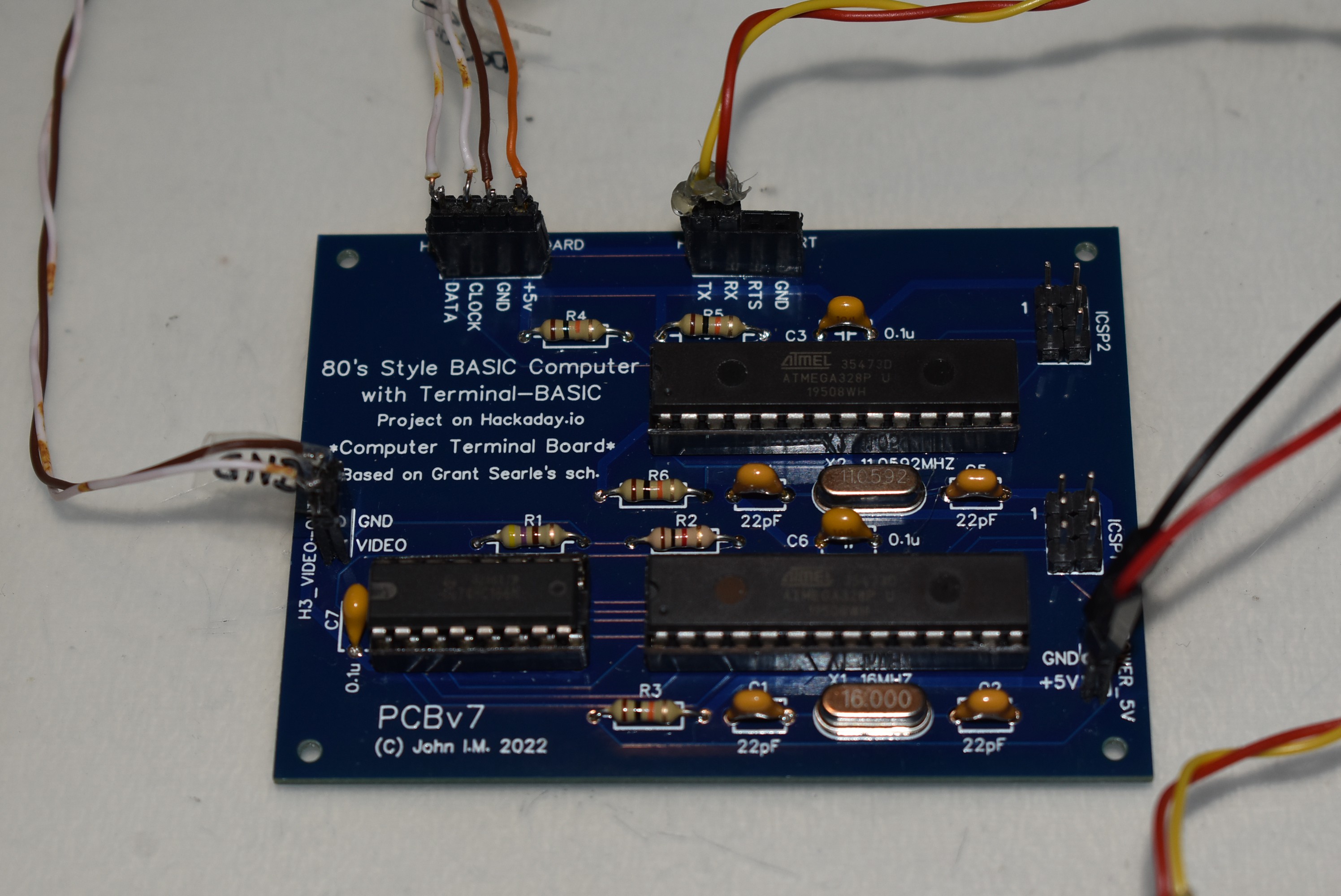
The finished assembled "Computer Terminal Board" (with wire connections for the subsequent testing) can be seen below:
Some testing was done (on the kitchen table!), as soon as I put together the whole system; that involved connecting the Arduino MEGA2560 (in the middle) to the microSD card board (on the right) and to the Computer Terminal Board I had just assembled (on the left). The colored plugs, in the upper part of the photo are, from left to right: 1. PS/2 Keyboard (purple) 2. Video Out (yellow) 3. Power input 7.5V (black)...
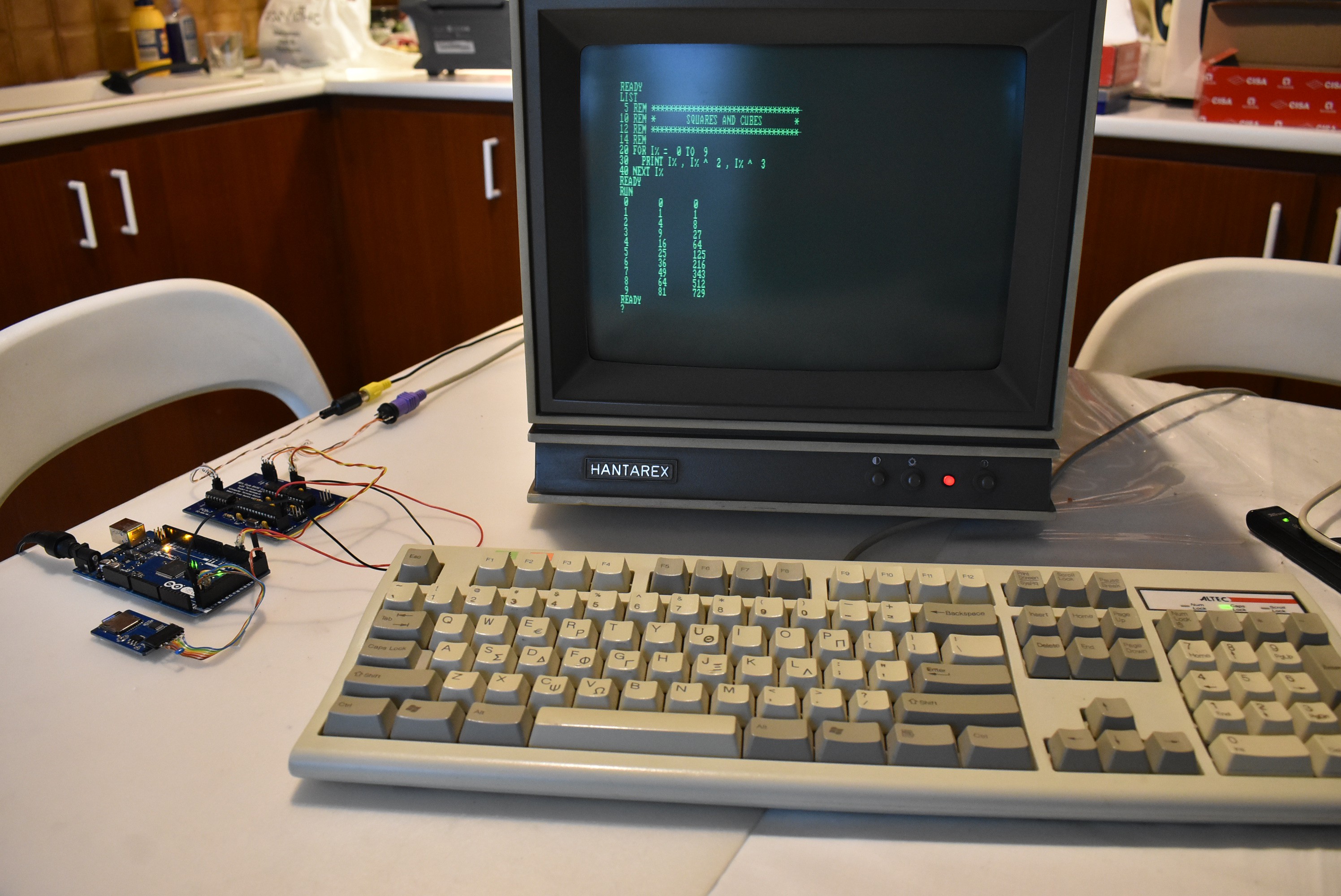
... and there you have it: The complete, working, "80's style BASIC Computer with Terminal-BASIC" !
The computer monitor pictured here is a HANTAREX. The assembled "Computer Terminal Board" worked nicely as you can see in the photo; the picture on the monitor screen looks crisp and solid.
PCB's finally arrived a couple days ago! I ordered them at:
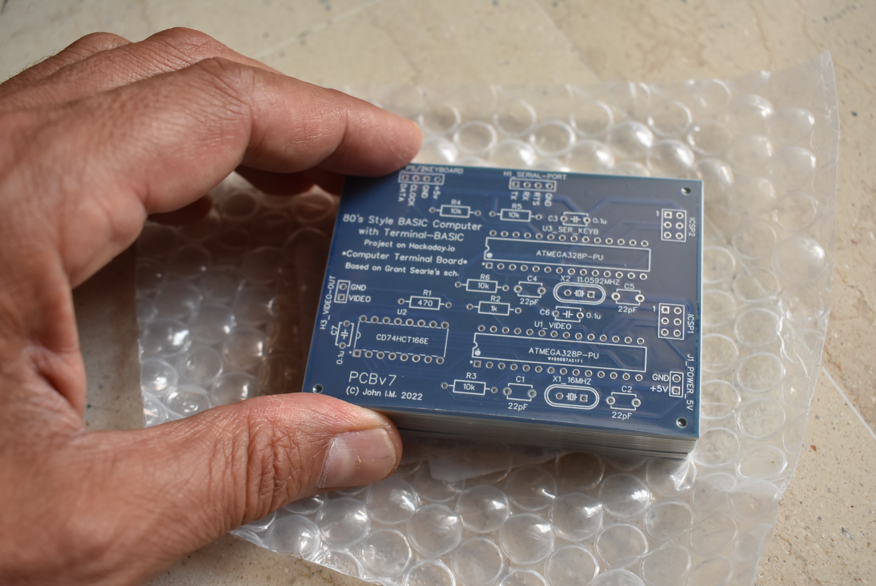
This is the first time I ordered PCB's from them. And it was a wise choice. The merchantise was carefully wrapped in foam plastic foil and the PCB's were nicely stacked and vacuum packed.
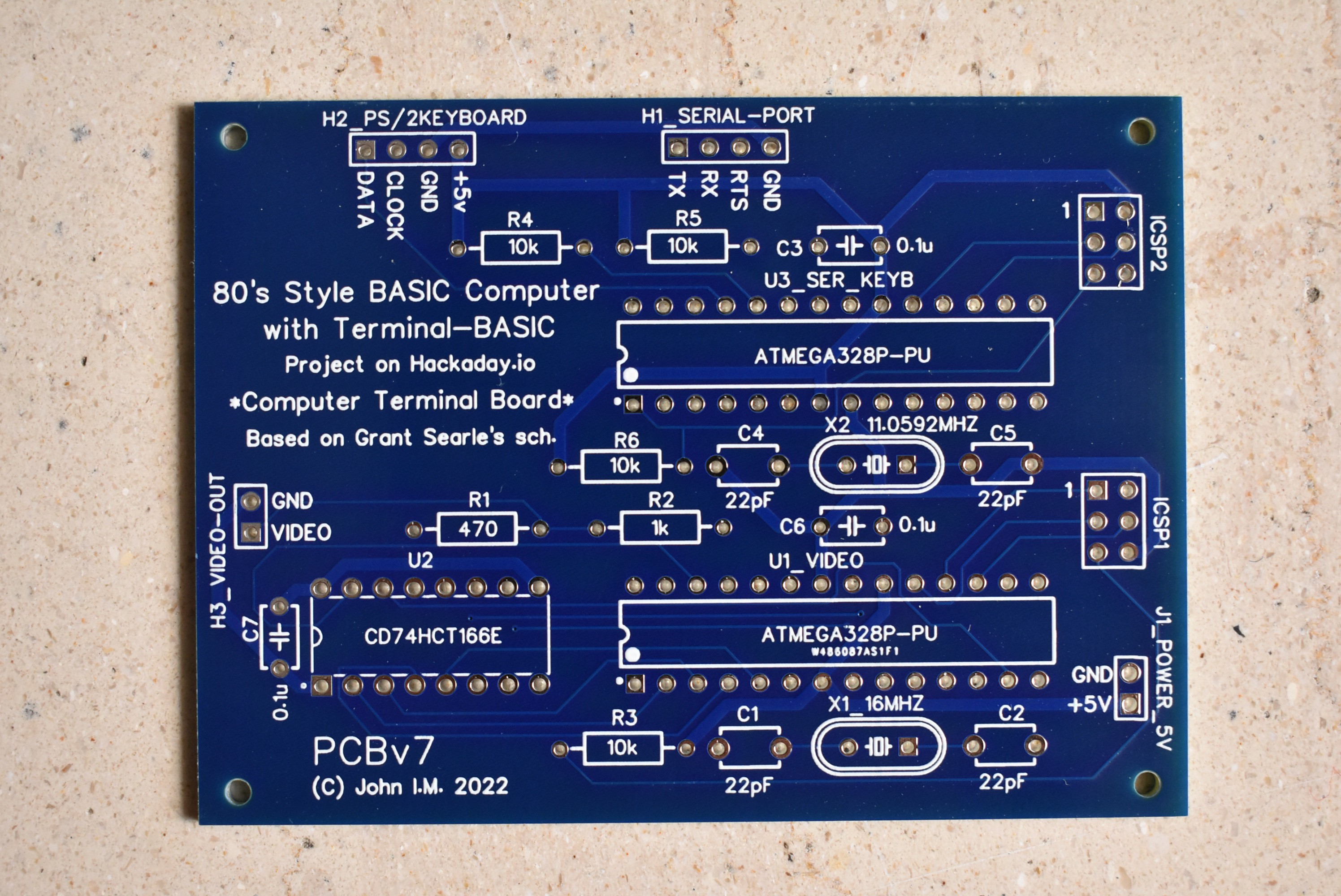
The quality of the PCBWay's boards is really high! All tracks, vias and pads are perfectly reproduced; I especially stress the vias because they are a very delicate kind of pcb tracks. Moreover, I know that the boards go through a continuity test at the factory, to verify that all connections work as expected. So I had peace of mind I wouldn't need to worry about any such defect; and this is great! Before I go on with populating the board, lemme show you what the actual bare board looks like:
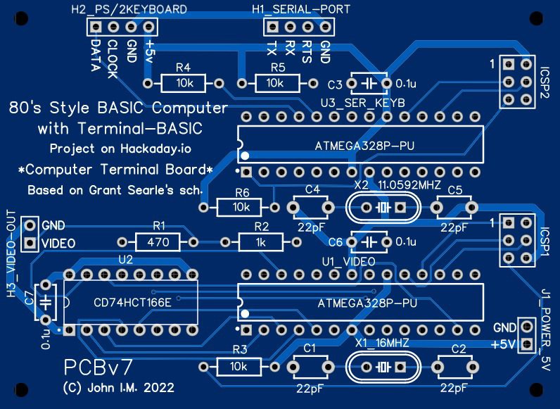
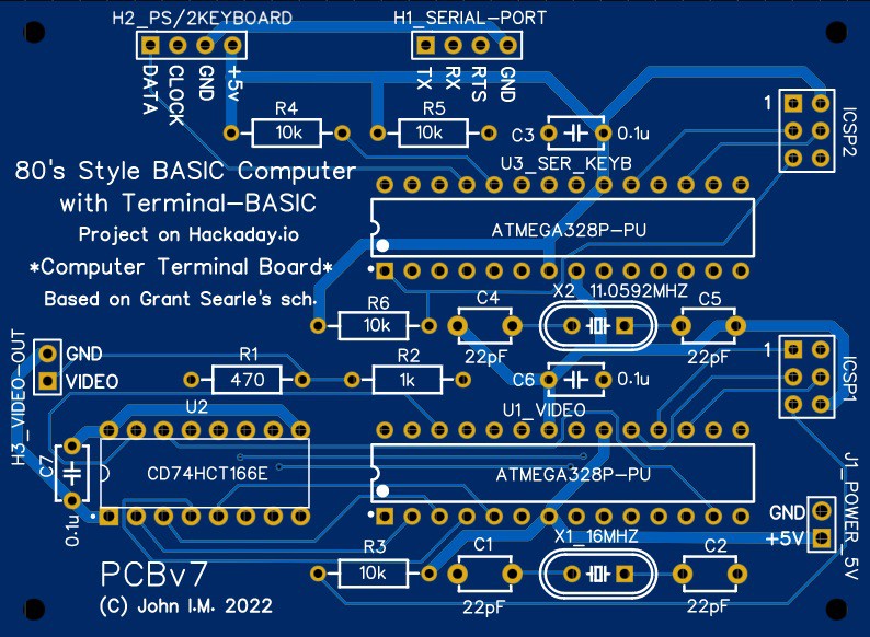
And this what I expected to see, according to my design (this is a preview from the CAD app):
The real thing looks exactly as it should have, according to the Gerber files I uploaded on their web site. So, very accurate fabrication of my design.
I must also mention that the whole process of ordering from PCBWay and tracking the package was simple and swift. Boards arrived within a few days. I definitely recommend PCBWay for quality manufacturing of your own pcb's.
So, I decided to design a PCB for my project. This PCB hosts the "Dummy Terminal" circuits and is referred as "Computer Terminal Board" on the PCB. I used Grant Searle's schematic of the "Video & Serial/Keyboard Interface" (named "Video&Keyboard,SerialBoard" in the project Details section), with just minor modifications: 1. I added two ICSP ports for programming the microcontrollers without physically removing them from the circuit. 2. Decoupling capacitors were added to all 3 ICs.
This particular design of the PCB is double-sided with vias.
As soon as I receive the actual boards I'll post some update. Hopefully, this PCB will give the "80's Style BASIC Computer with Terminal-BASIC" a more robust "body" after the successful testing of the project on breadboard.
P.S. About the ICSP headers: The need to add ICSP (InCircuitSerialProgramming) headers on this board was realized when I tried to modify the software in the ATmega328P's (specifically, the "Video" ATmega328P) in the breadboard prototype. Each and every time, I had to remove the chip from the breadboard and insert it into a separate programmer (STK500); this proved to be cumbersome. The other alternative is to leave the chip on the PCB and use ICSP programming; for that, you use only 6 pins of the IC, which are broken out to the ICSP header. Just connect a serial programmer to the ICSP header (I used the STK500) and program the chip in place.
 John
John