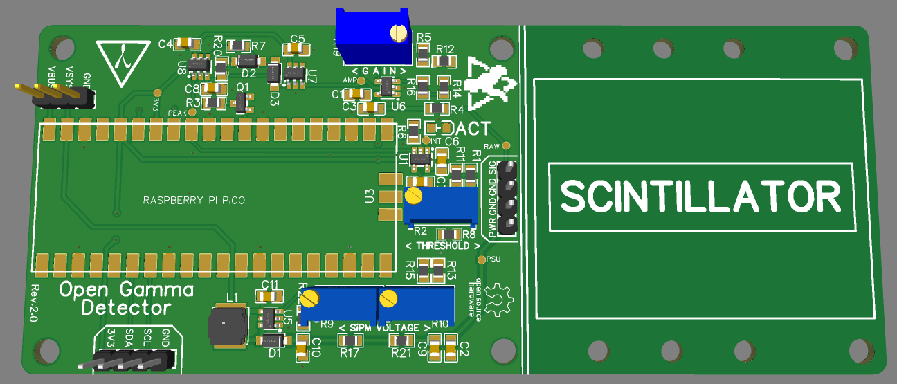
It didn't take quite as long as expected, now it is here: the revision 2 board!
Like I announced in the last project log this new hardware revision includes following changes:
- Custom preamp gain so that you can use different scintillator sizes, SiPMs and of course, change the energy resolution and range.
- Custom PSU voltage thanks to the new MAX5026 DC/DC converter, specifically made for these kinds of applications (low noise <5 mVpp @ 30V). It includes some potentiometers so that you can set the voltage anywhere from 28 V to 33 V.
- The peak detector/sample and hold OpAmp OPA2354 has been switched for two OPA357s which are mostly identical. As preamp I am now using the OPA356 which has double the Gain Bandwidth Product (200 MHz) and its gain can be adjusted too now.
- Improved PCB layout which includes a better mechanical structure and getting rid of the dodgy pin connectors (caused me some headaches lol). Also includes space for you to mount the scintillator on the board so that it's one single mechanical unit.
- Custom I2C header for the Pico so that you can use it to expand its use case to your own preferences, e.g. connect it to a display, communicate with other microcontrollers, etc.
- Additional place for an (optional) LM4040 voltage reference on the back side of the PCB. That's the one recommended for the Pico according to its datasheet (and also it's one of the cheapest for the output accuracy).
- All the power pins are broken out now so that you can tinker with different power delivery solutions or even battery-powered operation. See the Pico's datasheet for more info on this.
All the required parts should be in stock right now in sufficient quantities and I hope it will only get better with time. If not, then I will probably switch out some of the more important parts again, depending on the significance. Drop-in replacements for the OpAmps should be no problem though, especially because I'm not using the dual-channel versions anymore. Further, the number of BOM positions has been decreased by 3 and the number of individual parts has also been reduced to only 43 (not including the SiPM parts). Additionally, to make soldering faster and cheaper for production, the Raspberry Pi Pico will no longer need to be mounted with pin connectors and is instead soldered directly to the PCB thanks to its castellated holes!

As always, you can find all the updated electronics files, software and comprehensive documentation in the GitHub repository. This board revision will most likely accompany us for the next few months, heavily depending on user feedback, my own research and probably most importantly, the global chip shortage.
I'll keep updating the example spectra and upload new photos in the next couple of weeks here on Hackaday and on GitHub so stay tuned for more. Cheers!
 NuclearPhoenix
Discussions
Become a Hackaday.io Member
Create an account to leave a comment. Already have an account? Log In.