-
1PCB Assembly
![]()
![]()
![]()
![]()
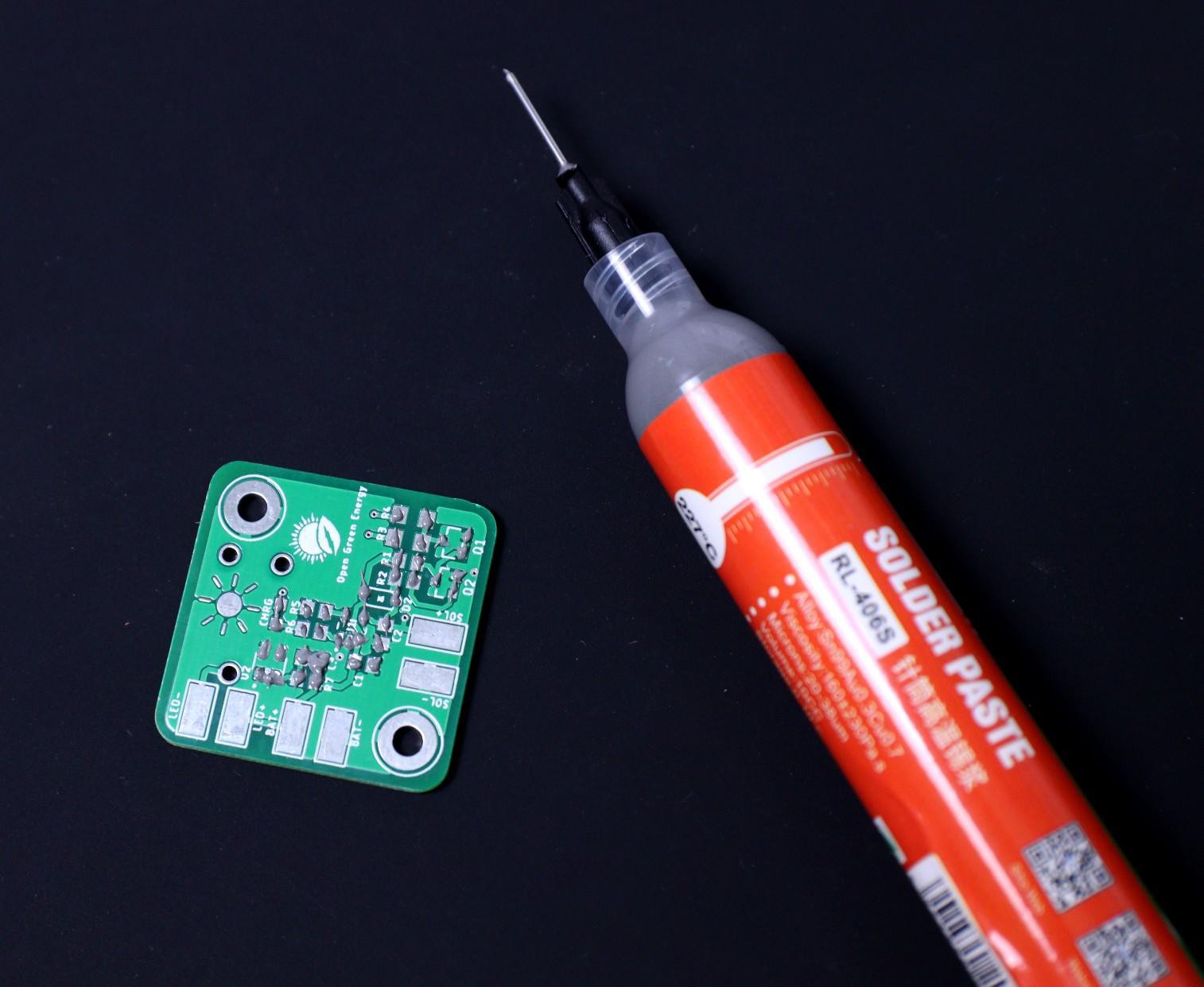
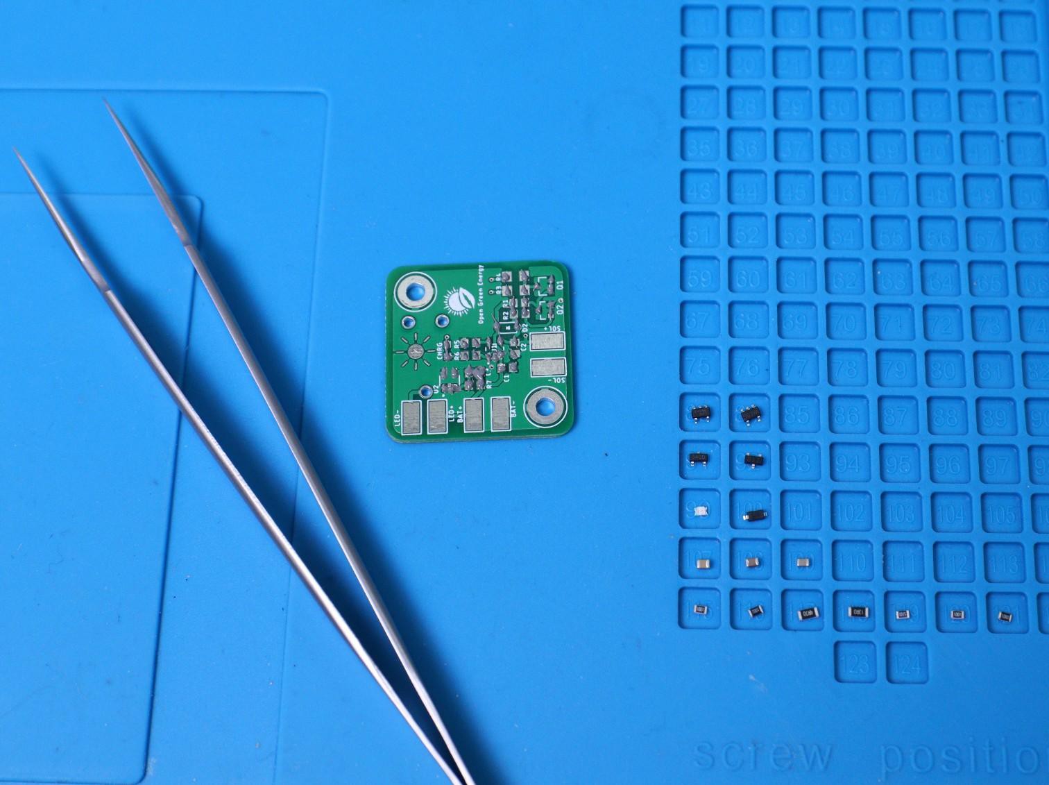
It's very important to first clean the PCB with some isopropyl alcohol. Then apply solder paste on the pads by using a solder paste syringe. Place parts with tweezers making sure that LEDs, chips, etc. are properly aligned. I like having a second board with no paste on it to see the alignment dots.
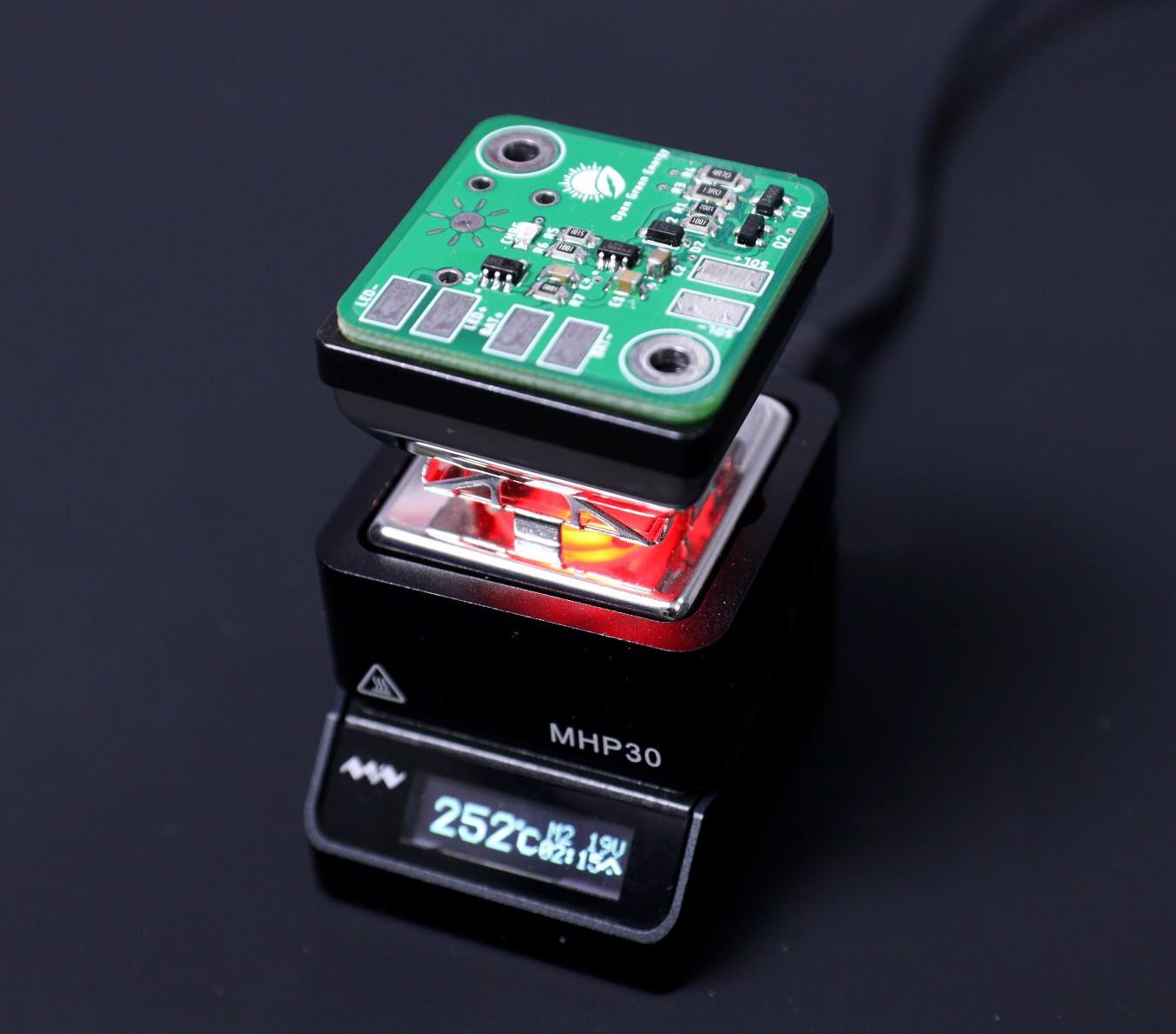
Now you have many options to cook the PCB like hot air soldering gun, Hot plate, reflow oven etc. I have used my Miniware MH30 hot plate to solder the PCB. Set the temperature according to your solder paste melting point and place the PCB on the hot plate.
It is important to look at the reflow profiles of all your components, to see how long you can heat your components for, and at what temperature. I usually just "wing it", and heat them at about 250C, for about a minute. You will see the solder melting, and the components being soldered into their respective places. Now you can turn off the hot plate and let it cool down completely.
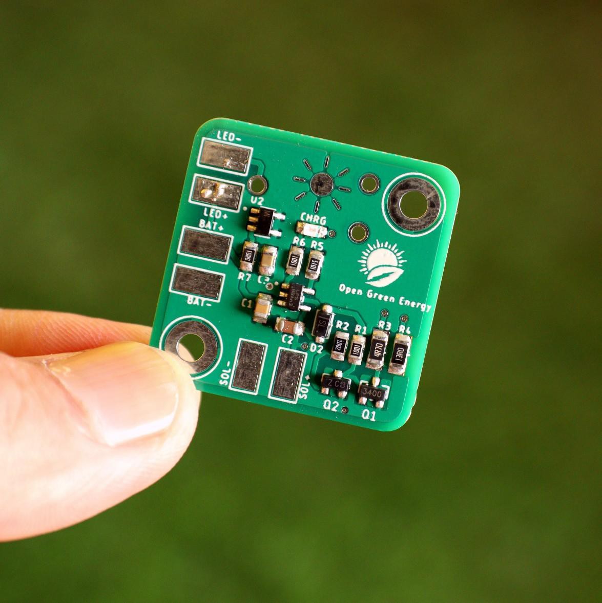
Once you have completed the soldering process it is important to remove the flux from PCB. Spray a small quantity of IPA (Isopropyl alcohol) Solution and clean it with the cotton.
Now the PCB boards are ready to use.
If you are not interested to assemble the PCB on your own, you may order the fully assembled PCB from the PCBWay store.
-
23D Printing
![]()
![]()
![]()
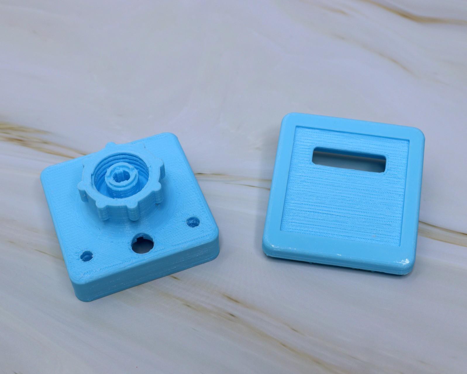
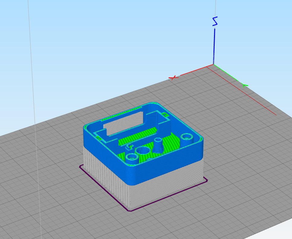
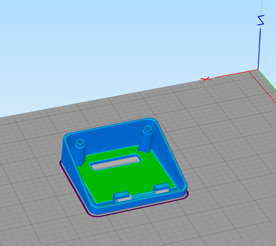
I have used my Creality CR-10 Mini printer and 1.75 mm PTEG filaments to print the parts. I have printed it in 3 different colors yellow, Orange and Cyan. The diffuser is printed in the transparent filament. You need a support structure for printing the main body and top cover.
My settings are:
1. Print Speed: 60 mm/s
2. Layer Height: 0.2mm
3. Fill Density: 25%
4. Extruder Temperature: 235 deg C
5. Bed Temp: 75 deg C
-
3Remove the Support From the 3D Printed Parts
![]()
![]()
![]()
![]()
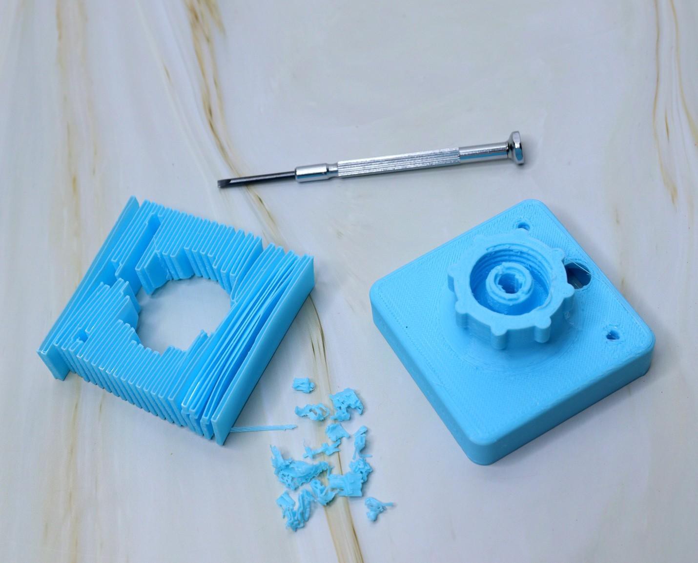
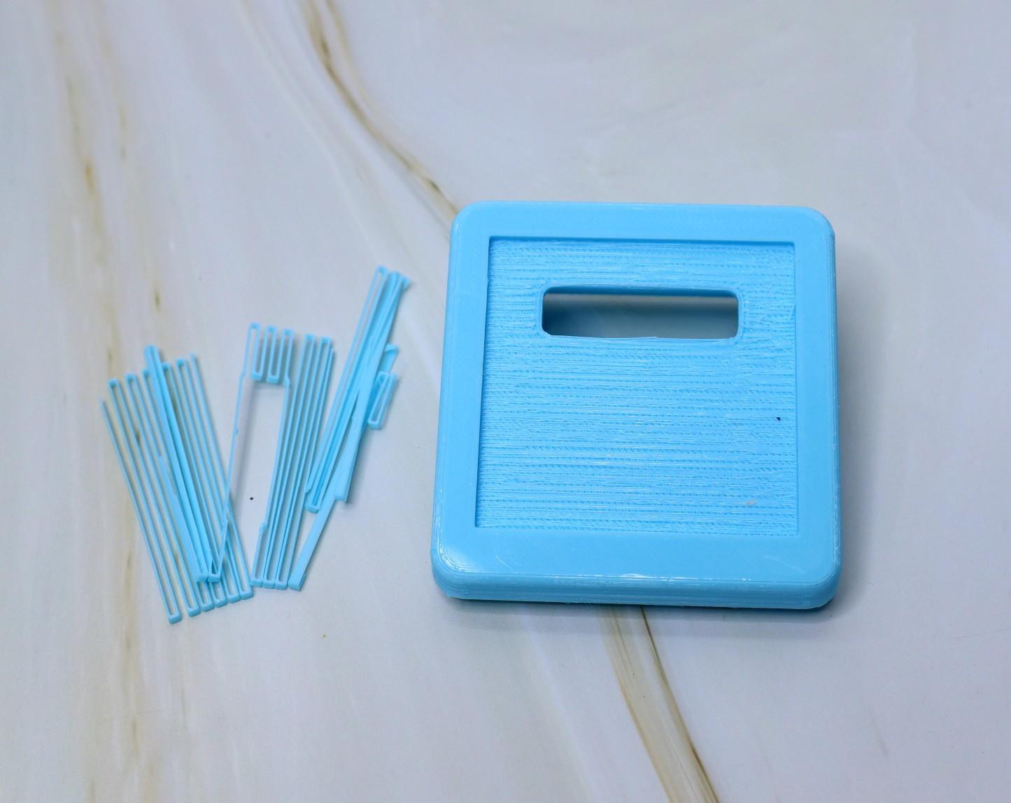
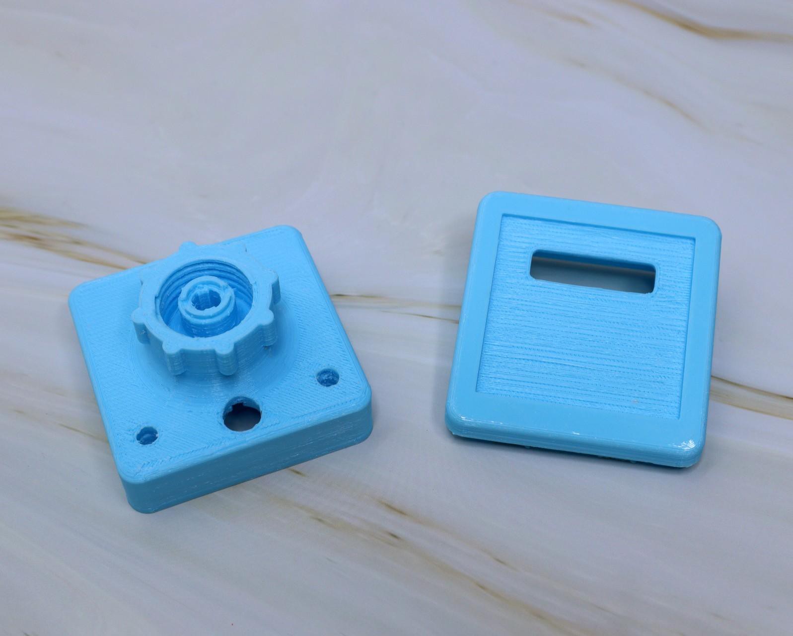
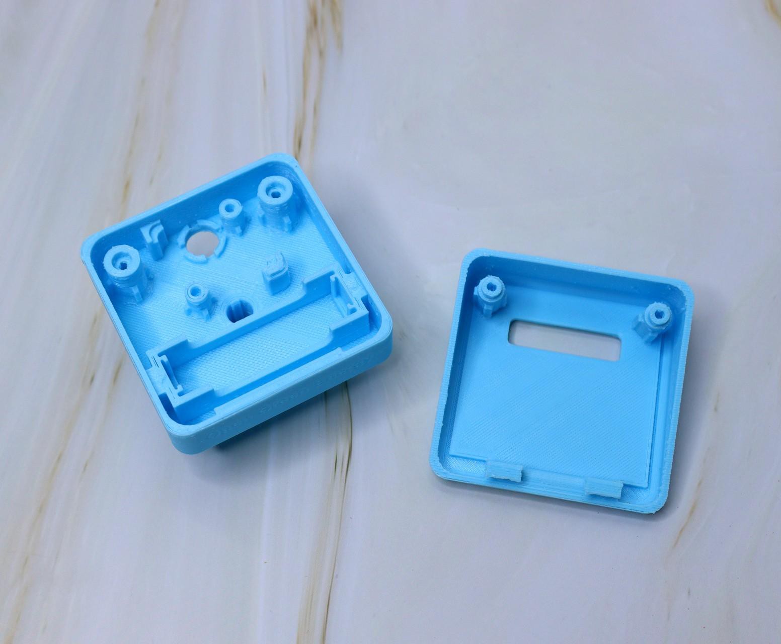
Both the top and bottom parts are printed with support structure, so we have to remove them before final use.
Removing support from the main bodies is quite easy, just squeeze them with fingers, and they will be easily separated from the main body.
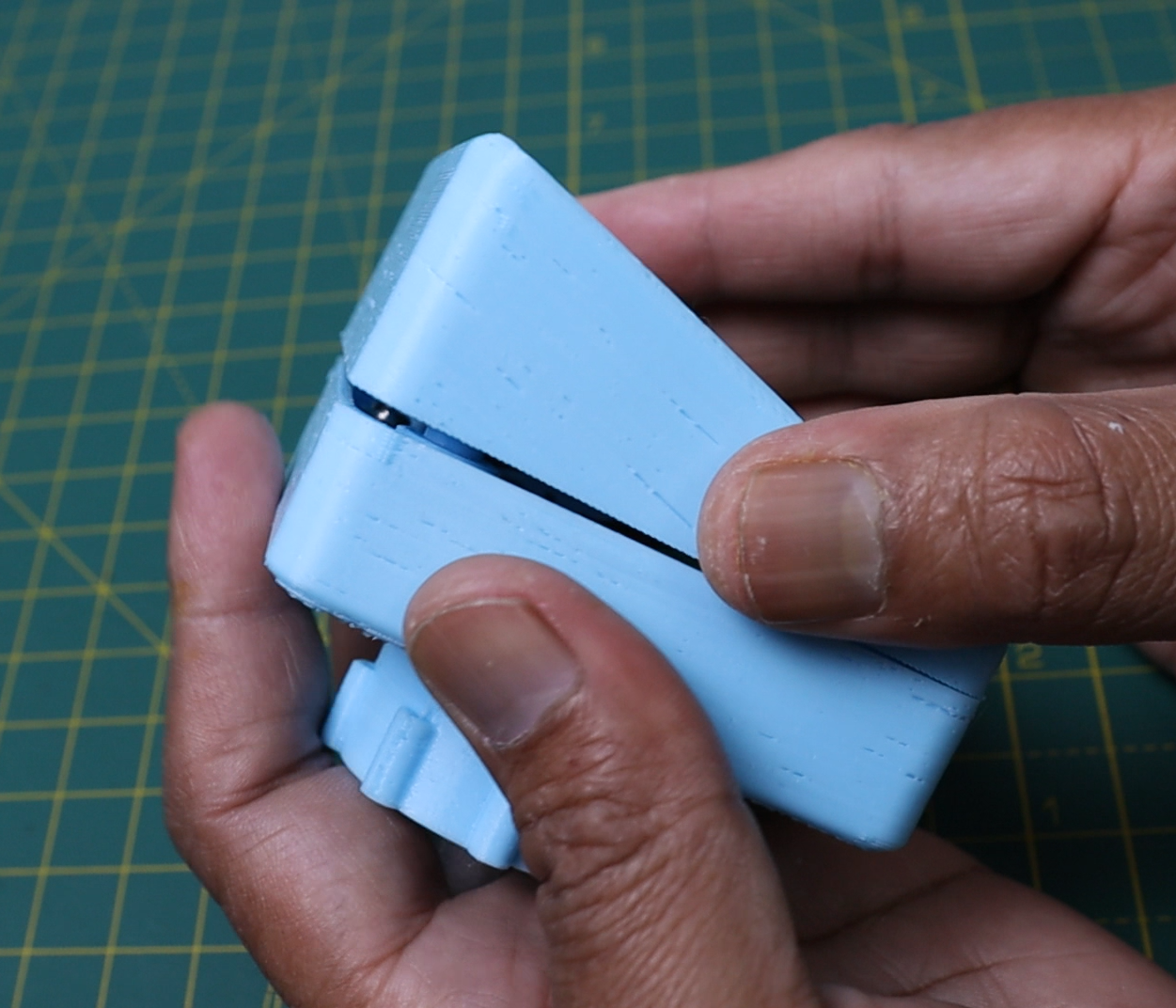
Removing the support from the cap threaded area may need a screwdriver or any sharp object. After removing the support, you have to smooth out the cap threaded area. You can easily do it by twisting and untwisting a few times with a soft drinks bottle.
-
4Mount the Solar Panel
![]()
![]()
![]()
![]()
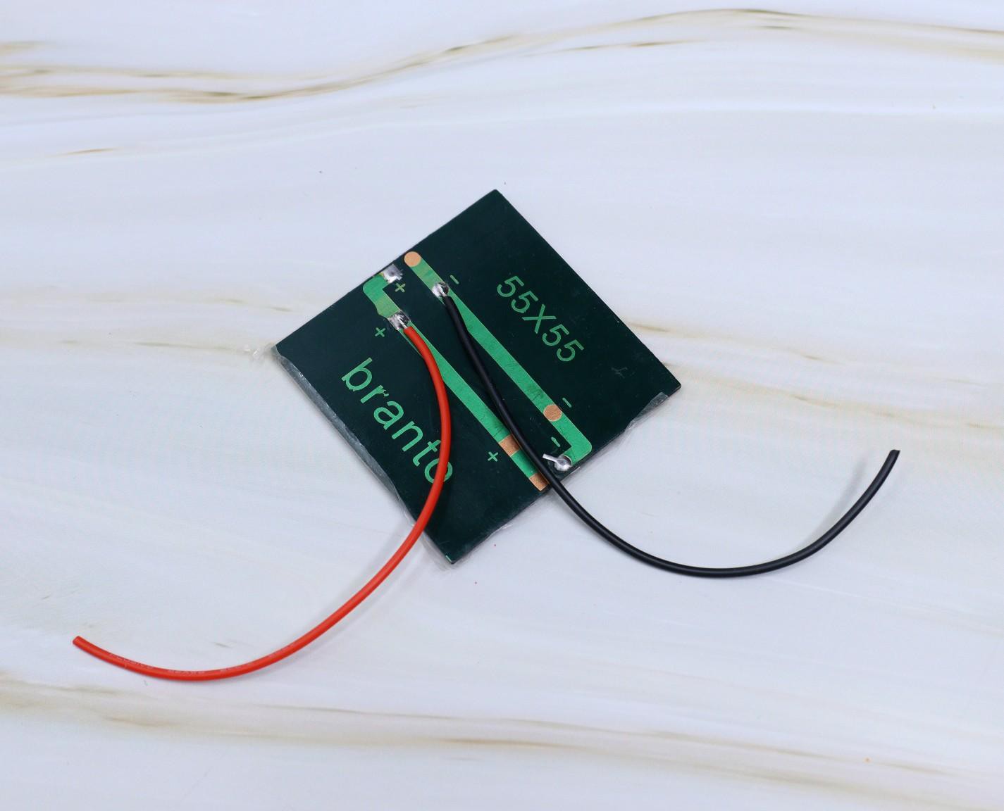
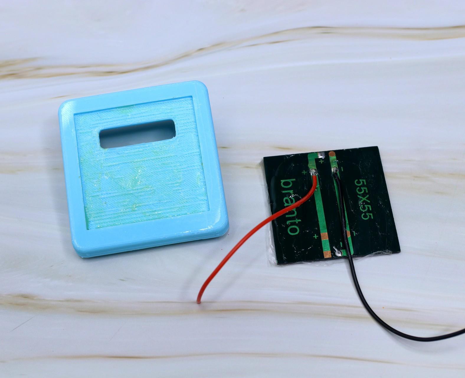
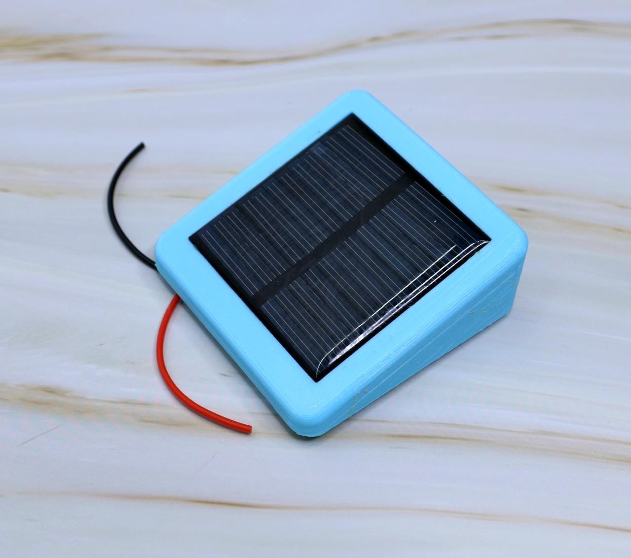
You have to use a solar panel that can be fitted to the enclosure. The slot is made for mounting a 60 x 60 mm solar panel. The solar panel that I have used here is rated for 6V and 50mA.
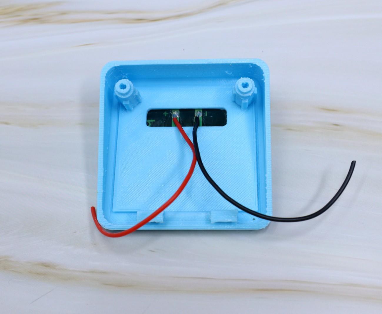
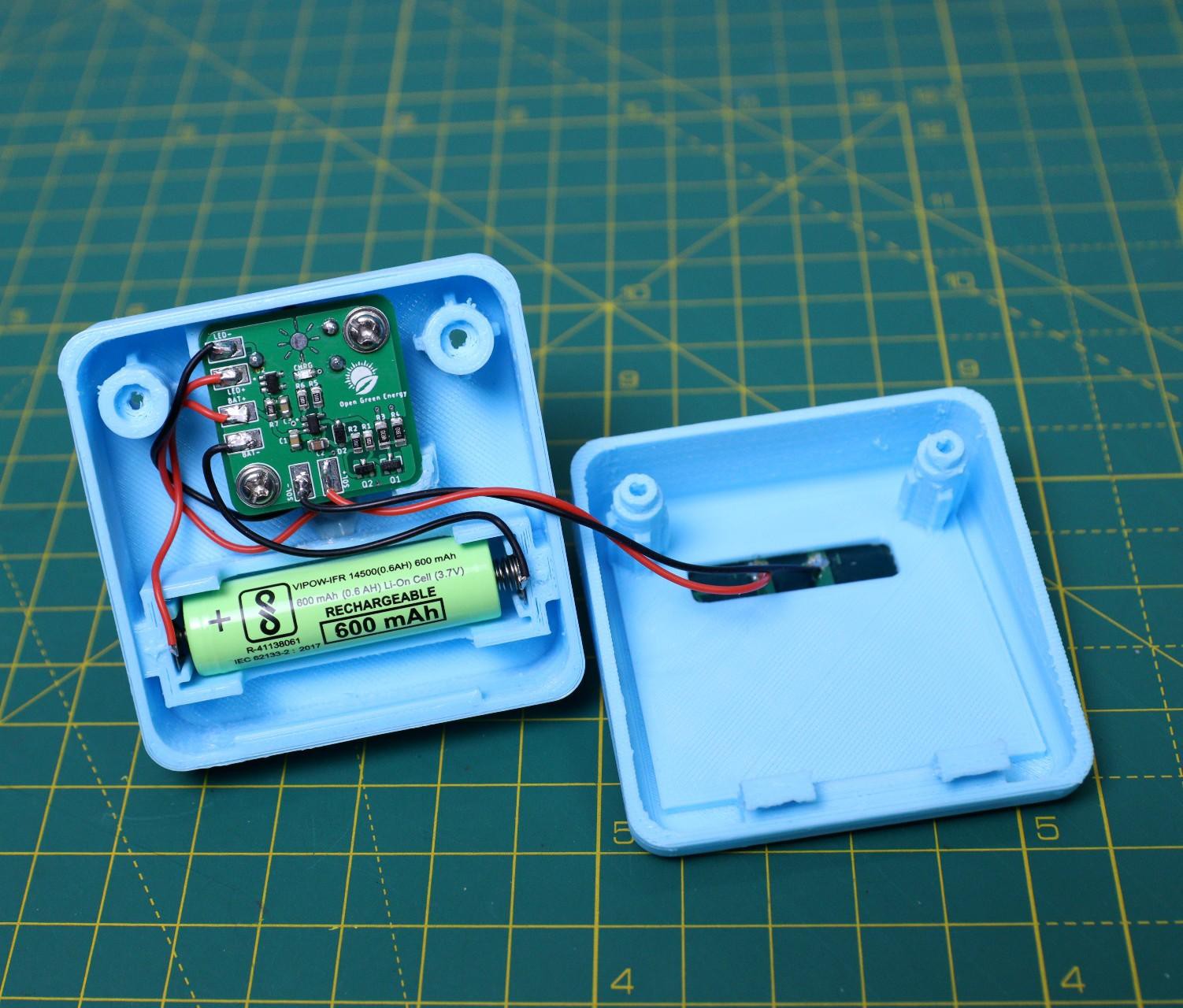
Insert the terminal wires from the solar panel into the slot in the top cover and solder them to the PCB ( SOL+ and SOL-). Mount the solar panel on the top cover by using epoxy glue.
Seal the panel from inside also, so that water will not enter the enclosure.
-
5Install the Battery Terminals
![]()
![]()
![]()
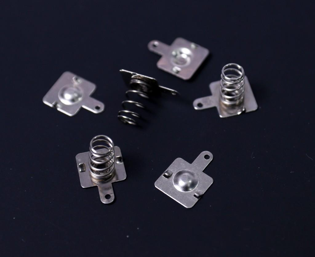
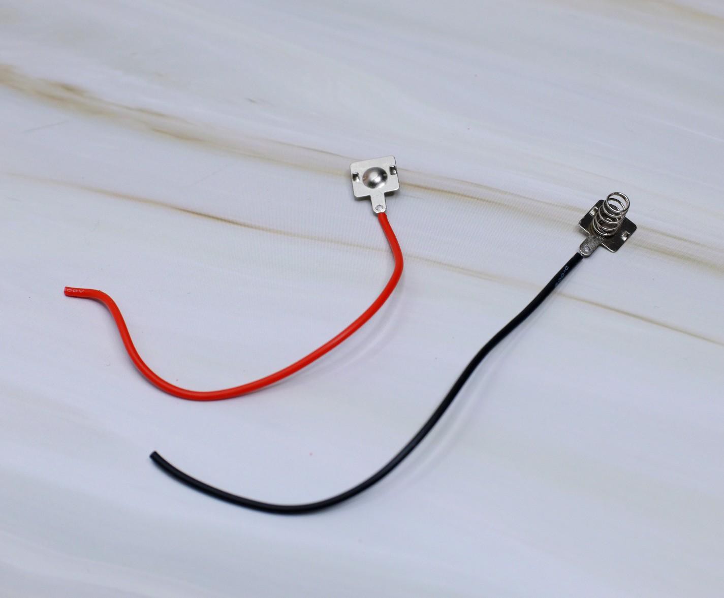
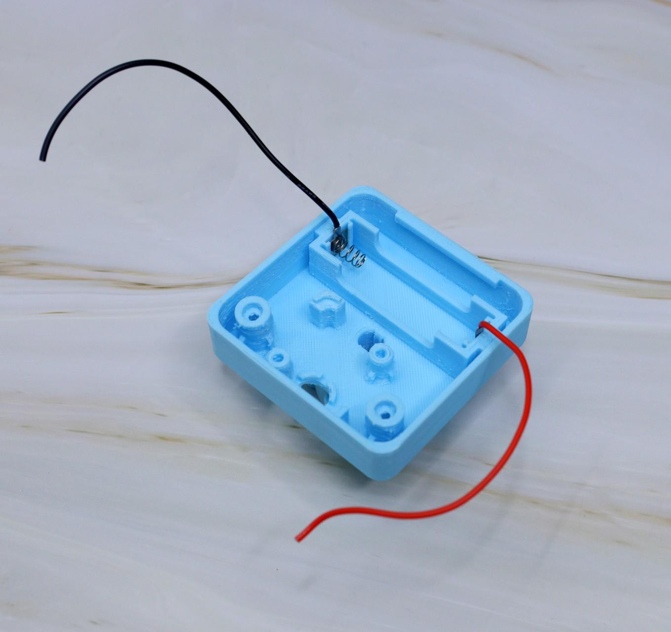
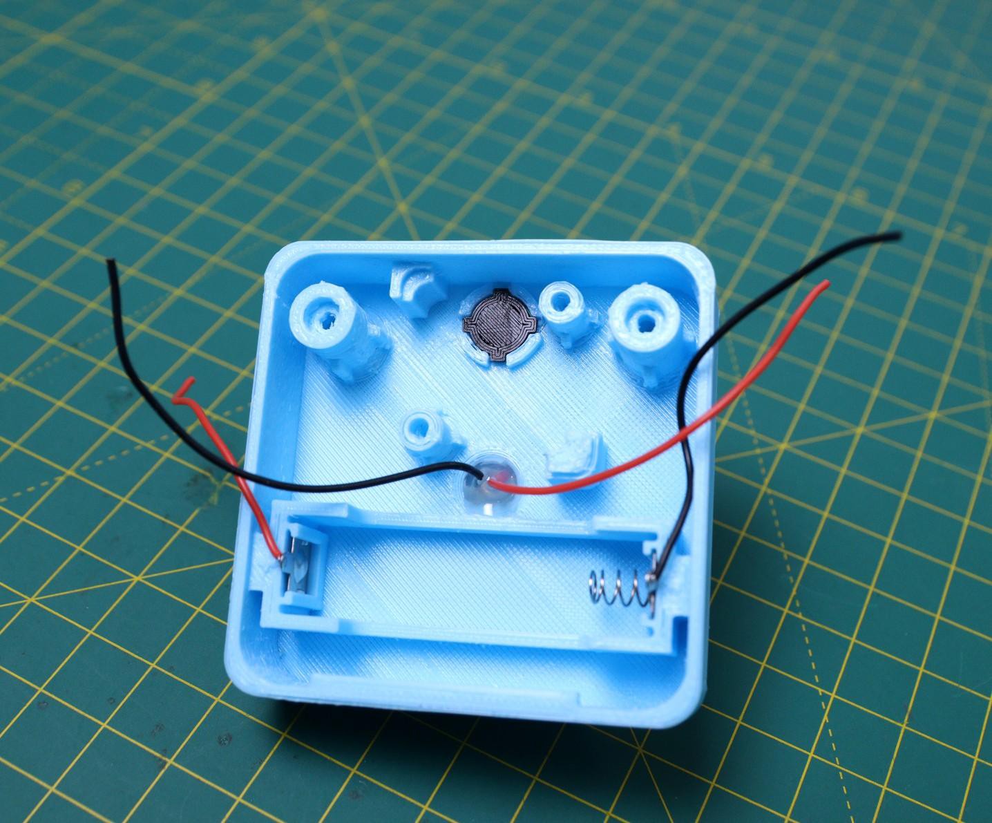
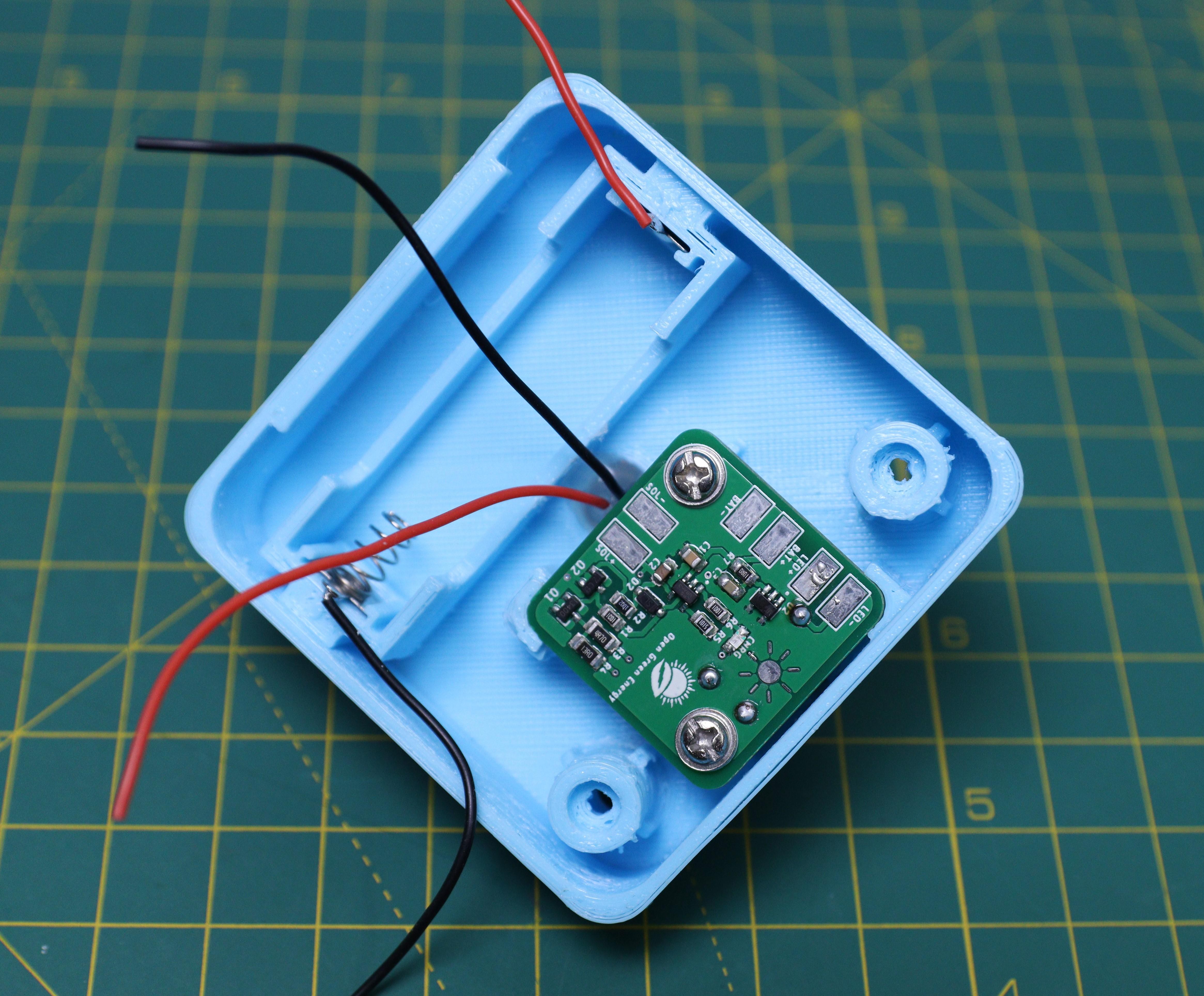
Solder 24AWG wires to the battery terminals. I always prefer to use red wire for the positive terminal and black wire for the negative terminal. The spring shape contact is the negative terminal. Solder the terminal wires to the PCB ( BAT+ and BAT- )
Then install the terminal plates into the battery slots as shown in the above picture.
-
6Mount the LED
![]()
![]()
![]()
![]()
![]()
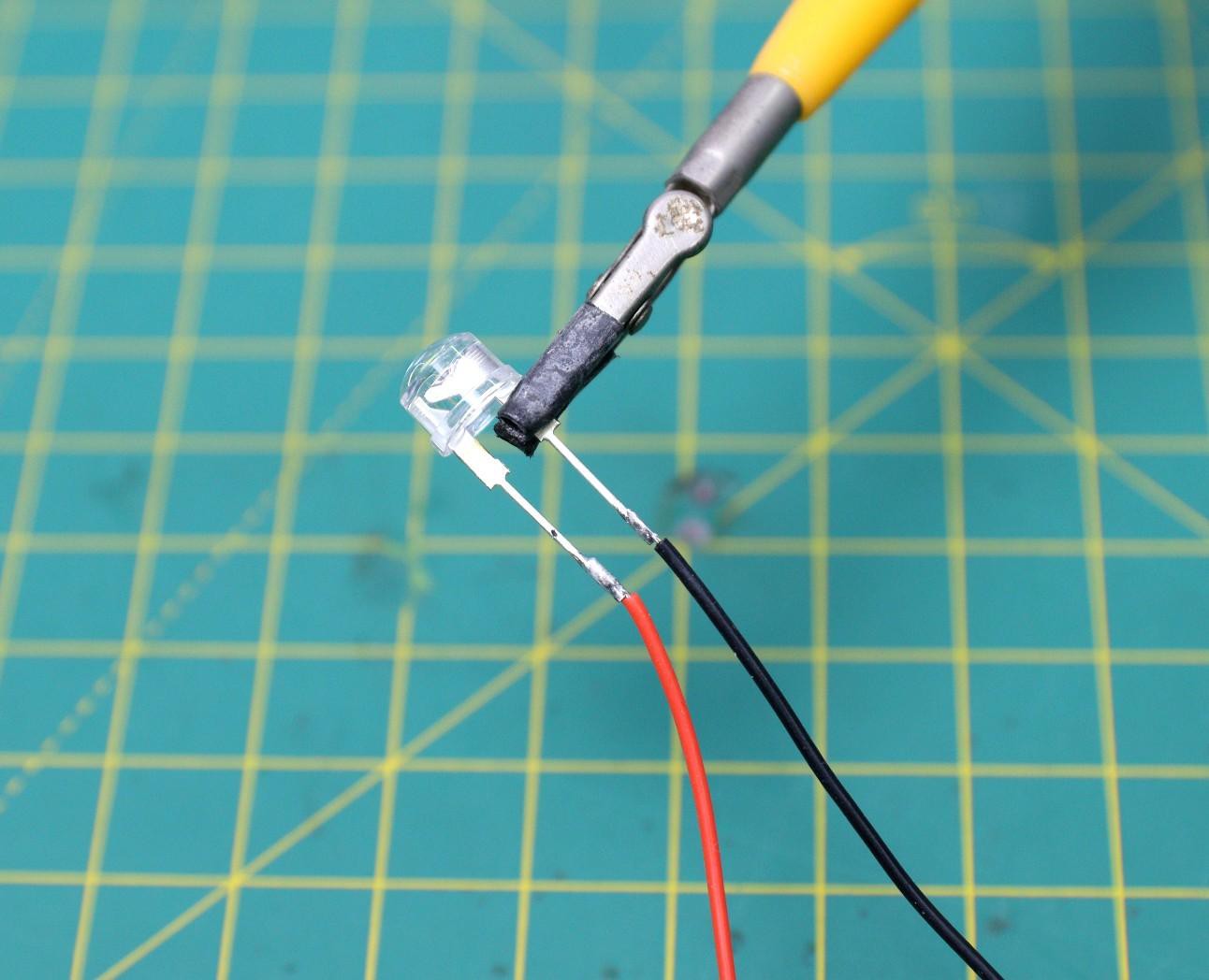
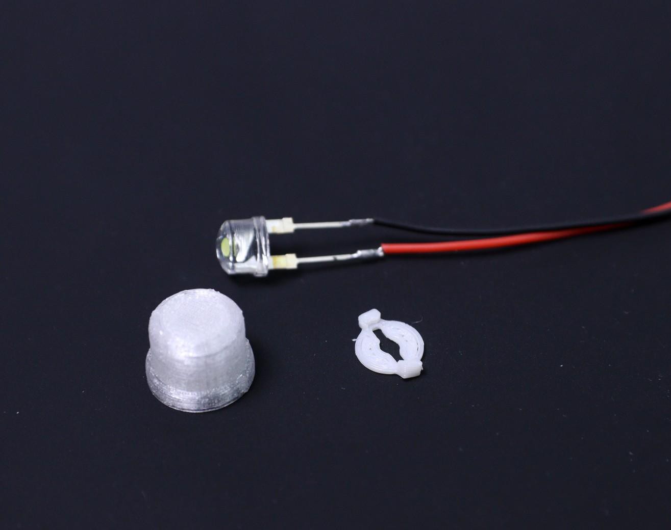
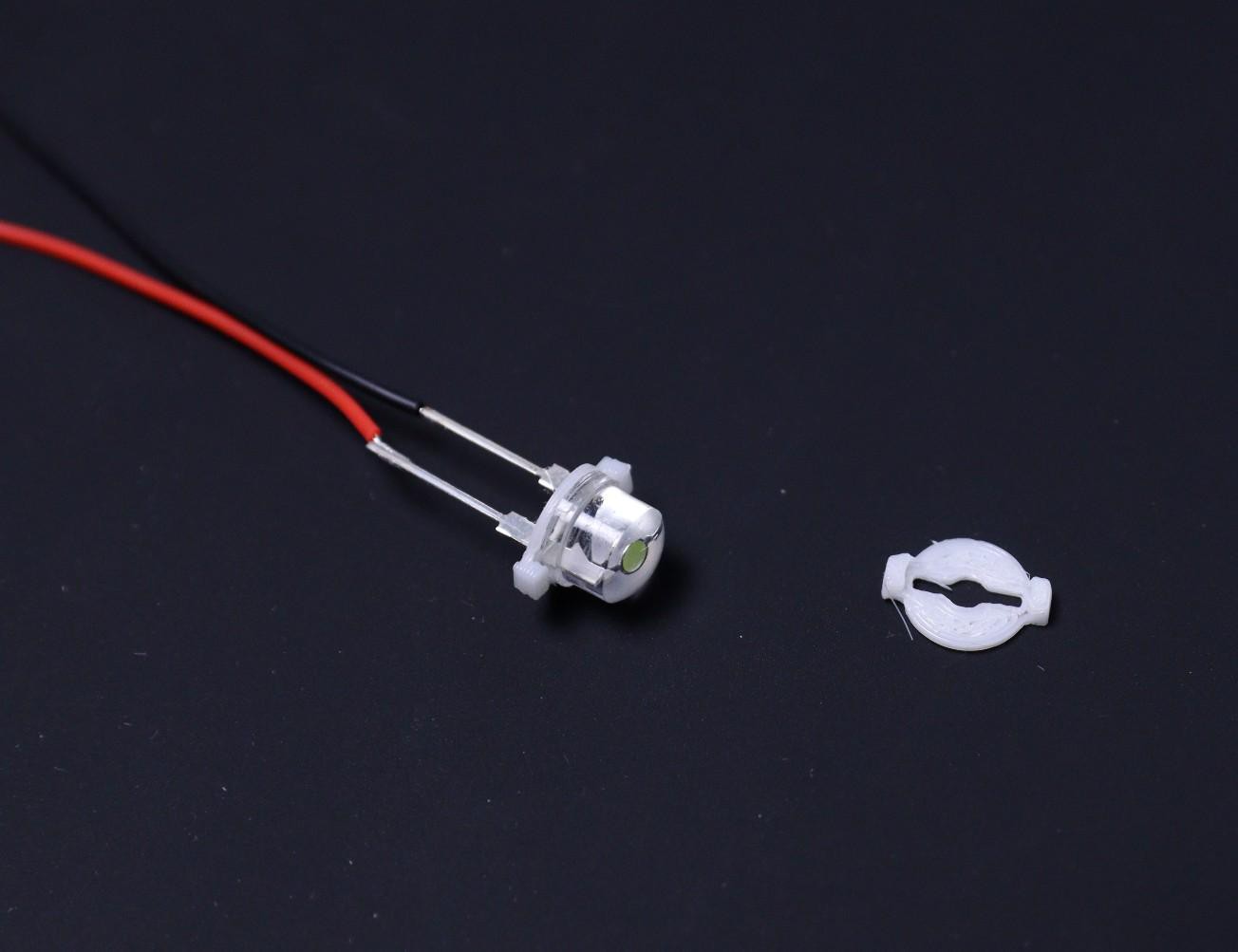
I have used an 8mm 0.5W straw hat LED. Solder 24AWG red wire to the positive terminal and black wire to the negative terminal of the LED.
Mount the LED into the holder and then install it into the main enclosure as shown in the above picture. The notch shall be aligned properly.
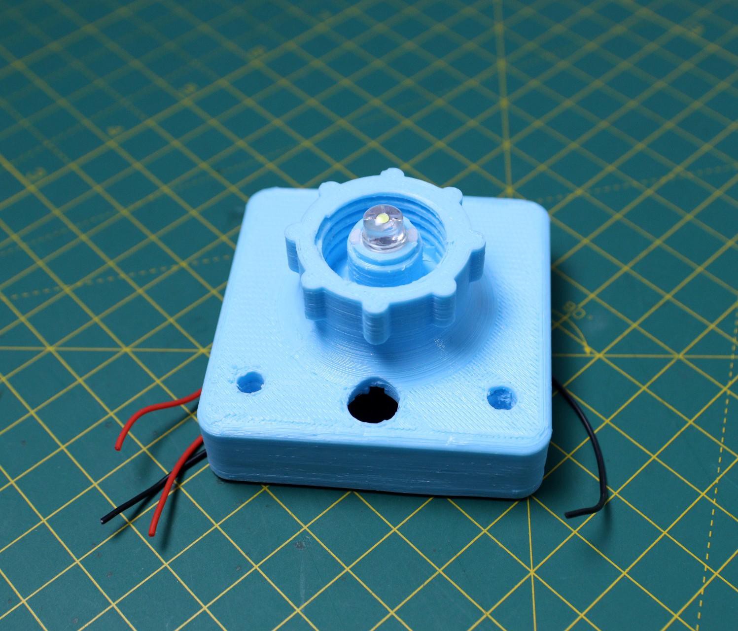
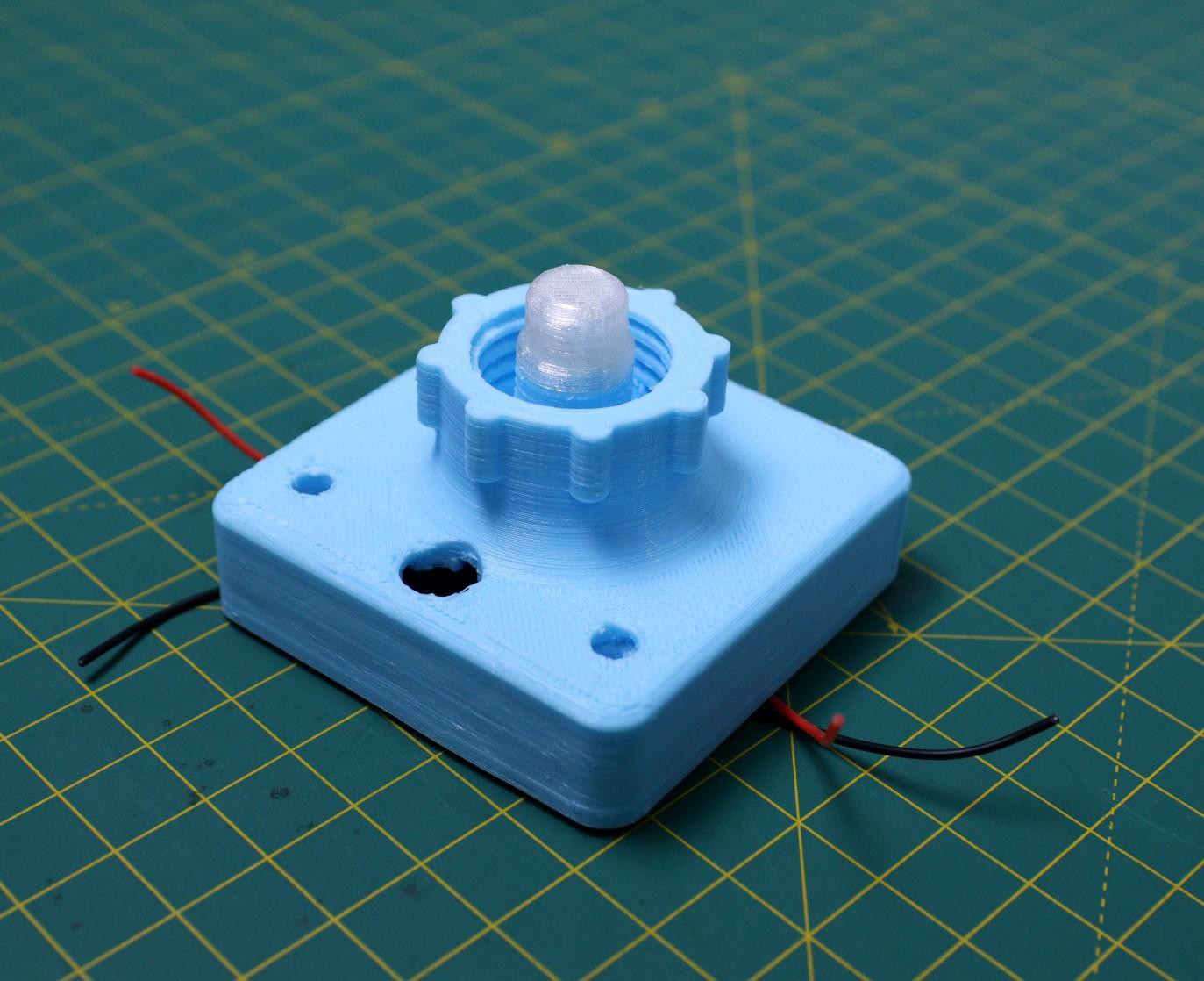
Now seal the LED from all sides by using epoxy glue. Then install the diffuser, you can apply epoxy glue to the joint.
-
7Install the Button Cap
![]()
Insert the Switch button cap into the slot given in the main body. You have to align the notches perfectly.
-
8Install the PCB
![]()
![]()
![]()
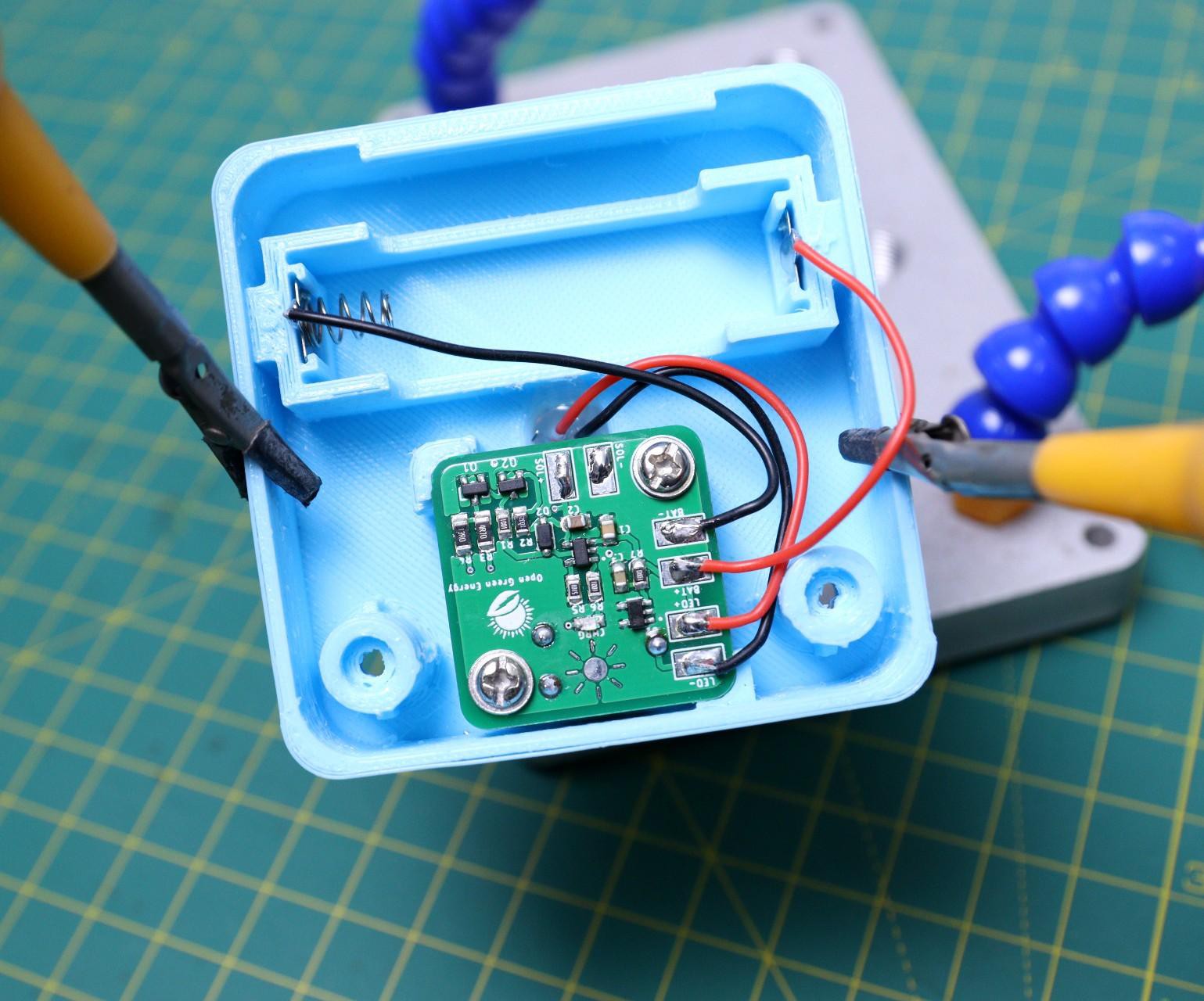
Align the PCB mounting holes with the mounting studs in the enclosure. Then secure it with two M3 screws.
Now solder the terminal wires from LED, Battery, and Solar panels. The polarity is marked on the PCB.
-
9Assemble the Enclosure
![]()
![]()
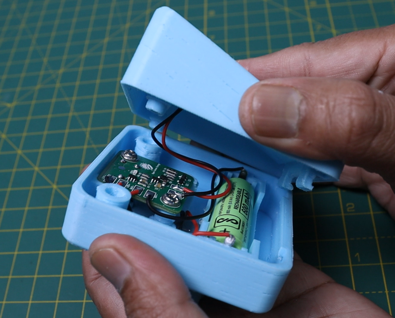
After installing all the parts, close the top cover by aligning the mounting studs. For a better joint, a snap and fit arrangement is also provided in the top cover. Now use M3 screws to tighten both the parts together. You may apply epoxy glue at the joints to make it weatherproof.
Now the lamp is ready for use.
-
10Prepare the Bottle
![]()
![]()
![]()
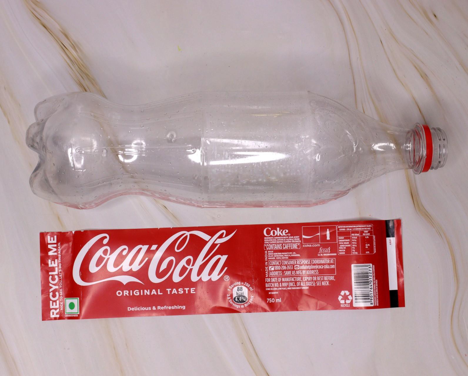
The solar lamp is compatible with any soft drinks bottle cap. Take an empty soft drinks bottle and clean it thoroughly.
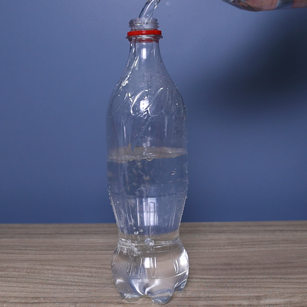
Fill the bottle with water and add a few drops of chlorine to avoid algae formation.
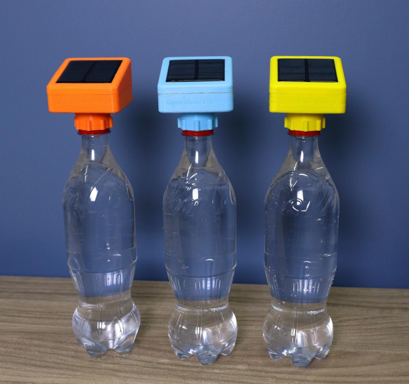
Close the bottle with Solar Bottle Lamp and your lamp is ready.
DIY Solar Bottle Lamp
Solar Bottle Lamp is a solar-powered light that is constructed from waste plastic bottles. The design idea is to reuse waste plastic bottles
 Open Green Energy
Discussions
Become a Hackaday.io Member
Create an account to leave a comment. Already have an account? Log In.