deʃhipu
-
Published
05/10/2022 at 12:14 • 0 commentsWith the second version being pretty much where I wanted it, I decided to go ahead, publish all the designs and code, and once I had done that, apply for the open source hardware certification.
The PewPew LCD is now officially certified open source hardware, with number CH000013.
I also submitted a pull request to include the board definition in CircuitPython, but before that, I had to apply for USB VID/PID numbers.
Once that is merged, I will need to add the board to circuitpython.org.
-
Version Two
05/10/2022 at 11:28 • 4 commentsWith an embarrassing failure that was the first PCB behind me, I went ahead and fixed the design somewhat:
![]()
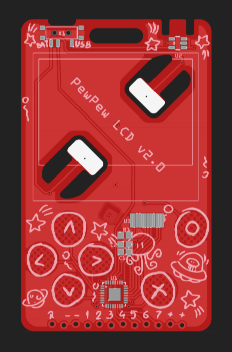
The flex connector for the display is now outside the display's outline, the microontroller had to be moved, the USB is now flipped to correct orientation. I ordered this time at @Elecrow because they had more choice of colors for the 0.6mm thick PCBs, and the quality seems to be better. A month later I had the first working prototype in my hand:
![]()
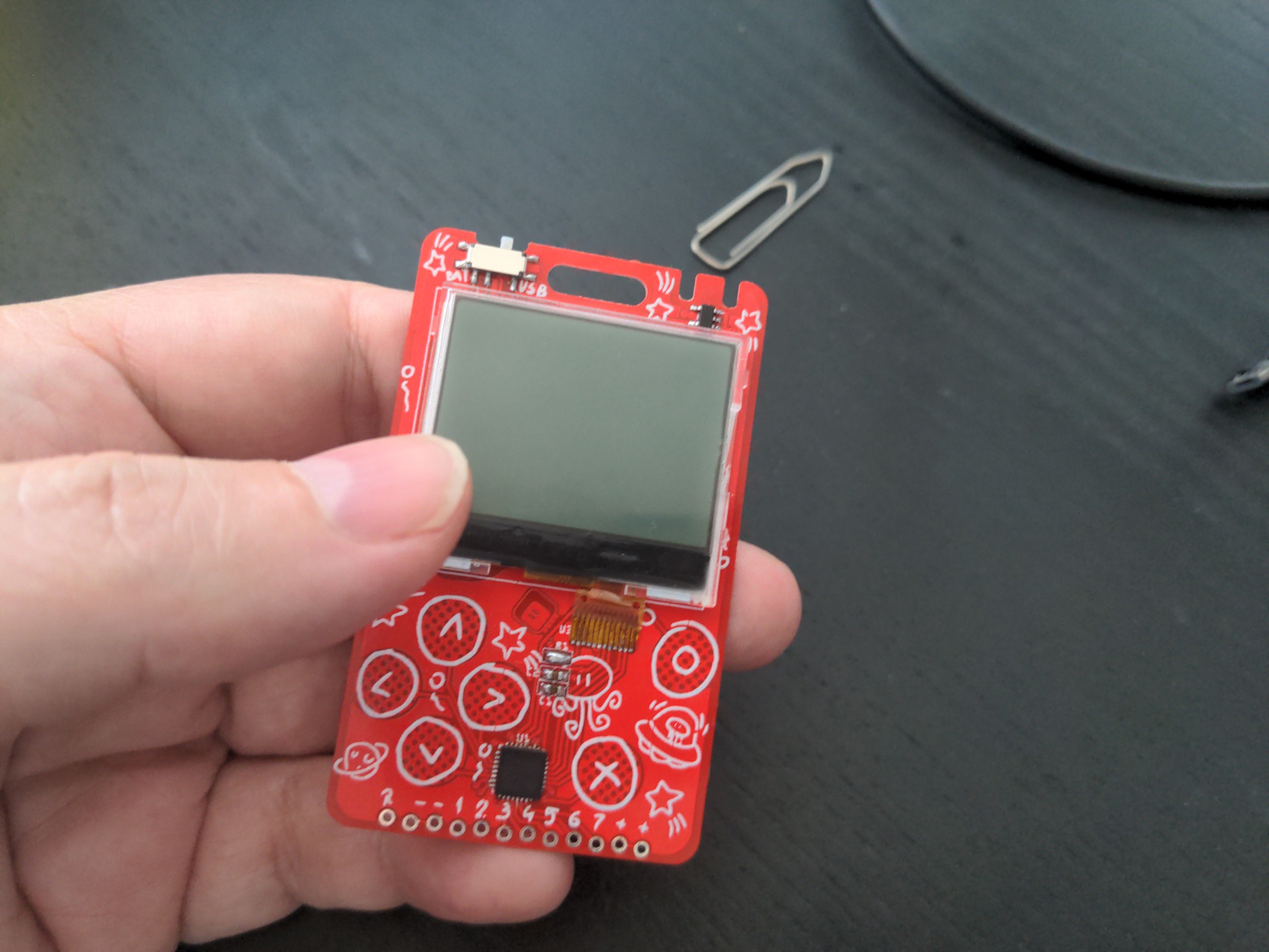
I adapted the software I used previously on the #PewPew OLED – the displays are pretty similar in how they handle pixels. One problem I encountered is that while the driver chip has the commands to flip the display 180°, and the breakout module I used to test them worked fine, the cheap displays I got for the device ignore those commands – I'm guessing they don't actually use the same driver chip, but some cheaper alternative.
![]()
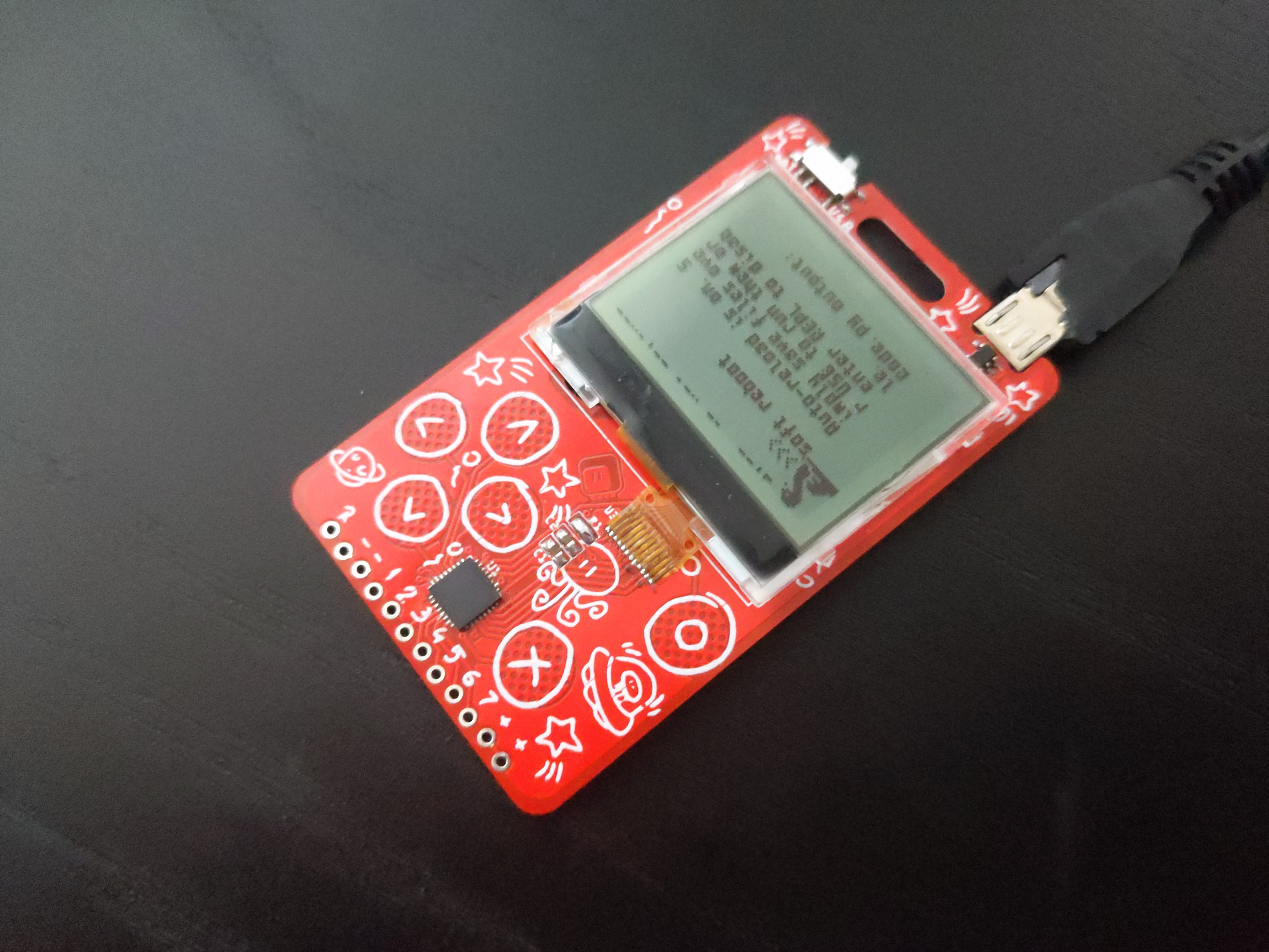
Fortunately this wasn't a huge problem, because displayio can rotate the display in software, and my own driver code can easily just output the pages in reverse order.
Mechanically there are a few small nits to pick in the design, but that is not going to change anything electrically. I discovered that I don't need the backlight resistor – you can see a solder blob in its place on the photo. The display itself is a little bit shifted to one side, about one millimeter – I will need to correct that. I will probably also change the way the traces go to the d-pad pads, so that it's harder to touch the traces instead of the pads. Finally, I'm thinking about adding some holes under the display to make it easier to glue it to the PCB. All of those are minor adjustments, though.
-
Environmental Cost of Displays
05/10/2022 at 09:47 • 0 commentsWhile reusing old displays wasn't initially the goal of this project, the goal of making it affordable lead straight in that direction, and then the Hackaday Prize came along with this category, so I thought why not submit it.
But while no lone hacker is going to save the planet with our toys, we can at least help somewhat by raising the awareness of the environmental effects of the technology we are using. So I went and tried to do some research about how bad the displays actually are for the environment.
On the surface of it, the impact seems negligible. It's mostly glass, silicon, some mild chemicals for the liquid crystals, some metals for the contacts, plastic for the case. But it turns out that most thin displays, whether they are LCDs, OLED, plasma, TFT, IPS or e-ink, share one thing with thin-film photovoltaic cells that makes them horrible for the planet: transparent electrodes. Of course you need transparent electrodes to bring electricity to all those pixels, if you want to also be able to see the pixels. Such electrodes are usually made of silicon, just like in chips, and to get the right shapes, they are etched in similar way that you etch copper on the PCBs. Except the best chemical for etching silicon is nitrogen trifluoride.
What is nitrogen trifluoride? It seems pretty harmless. It's colorless, non-flammable gas with pretty low toxicity. Easy to handle, pretty safe. However, it's an extremely potent greenhouse gas. How potent? 17200 times more potent than carbon dioxide. That's 17 thousands. Oof! It stays in the atmosphere for an estimated 740 years. And its concentration in the air is growing steadily at about 11% increase per year, as of 2011.
So yeah, let's see if we can reuse those displays we already have, and maybe rethink those solar panels a bit too.
-
First Hardware
05/10/2022 at 09:09 • 0 commentsIn the mean time, the PCBs that I designed for this arrived from @JLCPCB and I could assemble the first prototype. I can only give you one advice here: don't design PCBs while sick and with fever. Everything went wrong.
![]()
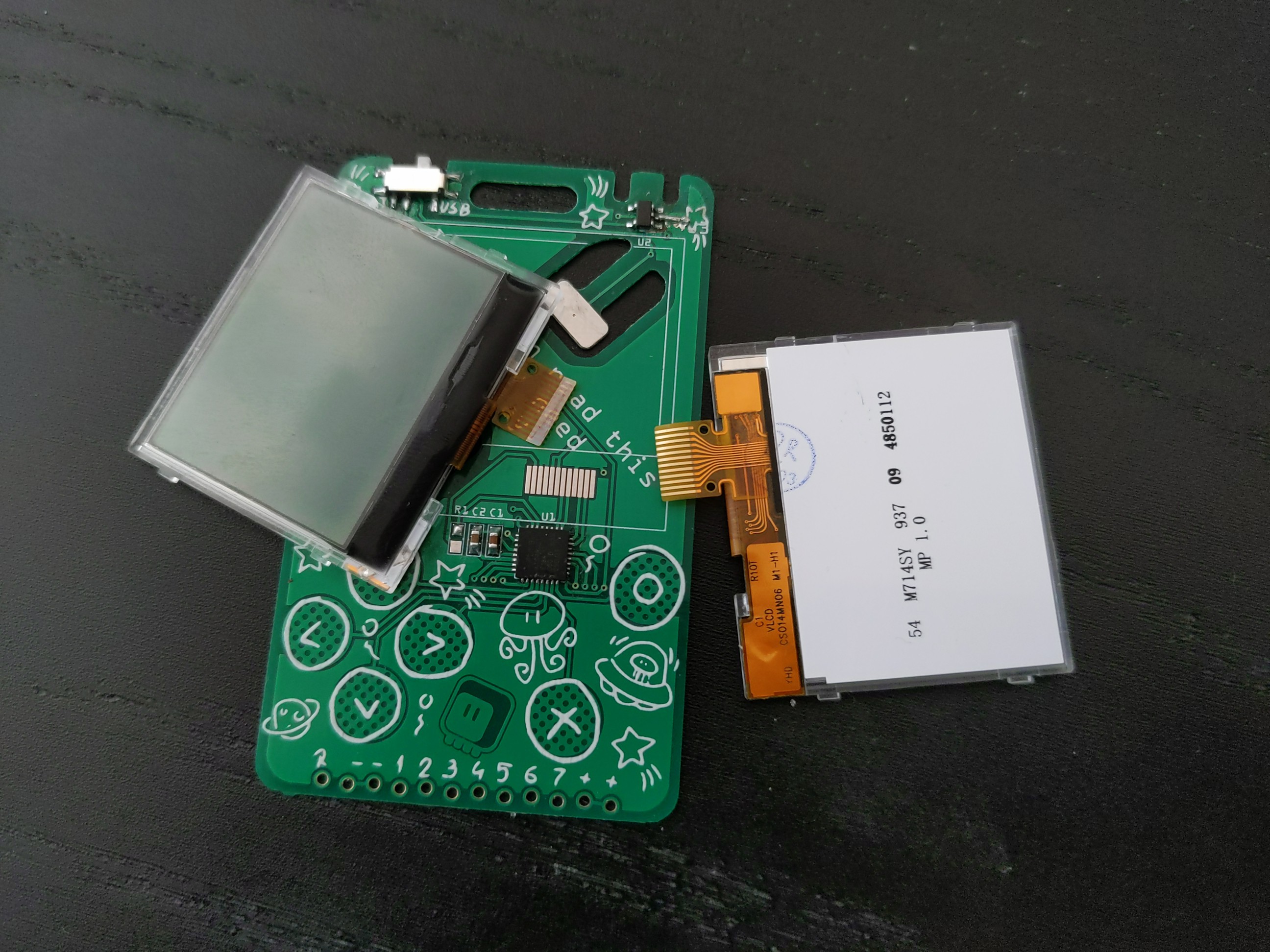
The display footprint had to be custom of course, and I designed it the same way it was done on the breakout I tested with – assuming the flex connector will be folded under the display and soldered there. Well, turns out the really cheap displays I got are a bit cheaper than the one on the breakout, and the flex connector only has metal contact on one side. The wrong side, of course. So I will need to redesign it to move the contacts outside of the display outline.
Fine, so I will need to make a second version for the display connector, but what about the rest of the device? Well, the rest wasn't very good either. I simply couldn't get the chip to program. After several hours of struggles, and some smoke coming out of the voltage regulator, I finally realized that I had the USB connector mirrored. It probably happened when I moved it to the other side of the board. Sadly, I burned one of the SAMD21 chips I had, and that's painful considering we have chip shortage and the next opportunity to buy more will be in a year from now.
At least the physical shape of the PCB is good. The battery connector works great, the expansion header retains a male pin header inserted into it just fine, the touch pads are in the right places and the USB socket fits the plug.
-
9-bit DisplayIO and CircuitPython
05/10/2022 at 08:39 • 0 commentsWhen I was testing that breakout board for the display I've chosen, I immediately noticed a funny thing: while it uses the standard 4-wire SPI interface, it actually only has 3 wires: SCK, MOSI, and CS. There is no D/C pin! So how is the driver chip supposed to know if you are sending it data to be displayed or commands to execute? Well, the answer is simple yet brilliant – before every byte, you send it an additional bit that says if it's data or command. So you effectively send it 9-bit words.
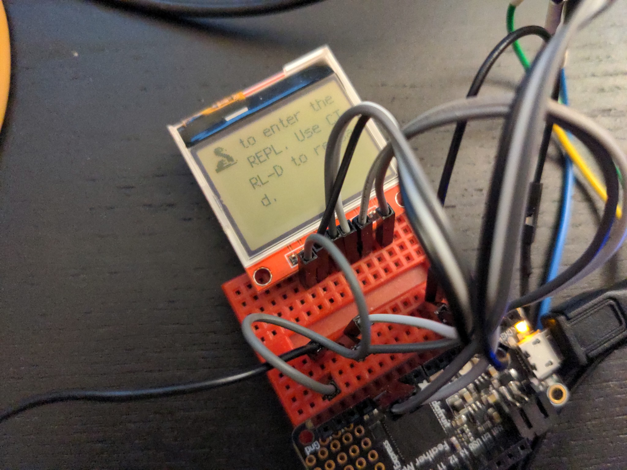
This is all great, and for testing it was relatively simple to just prepare the commands and data by shifting the bytes in the buffer and injecting the additional bits in between, but I really wanted this display to work with CircuitPython's DisplalyIO library, so that when your program ends, you can see the REPL console and any errors or other messages. This required a little bit more work, but I made a path that adds this functionality to DisplayIO's FourWire protocol implementation – basically if you don't specify a command pin, it will assume 9-bit SPI.
![]()
With this solved, I proceeded to make a board definition for my device, with the display's initialization compiled into the firmware, so that you can see things on the screen right from the beginning. Unfortunately I stumbled into a tricky bug then, which I wasn't able to fix, and had to take a little break until it was solved by Dan Halbert.
-
The Display
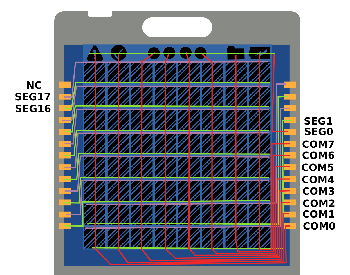
05/10/2022 at 08:06 • 0 commentsInspired by the Sensor Watch project, I initially thought about using a custom LCD screen, with just the right size and just the right number of "pixels". Since Joe Castillo was using a SAML22 chip in his design, which is a close cousin of the SAMD21 I use, and he's also interested in porting CircuitPython to it, it seemed like a good idea. But when I researched it a bit closer, it turned out to not be so great. Preparing a mock design of the display, like this:
![]()
I quickly realized that the QFN32 version of the chip will simply not have enough pins to drive it, and that a bigger and more expensive version would have to be used. Furthermore, I would still have no good way of displaying the error messages. And of course ordering such a display would only contribute the all the electronic trash lying around. So I decided to go with an existing display after all, but maybe take a look at the older LCD screens available.
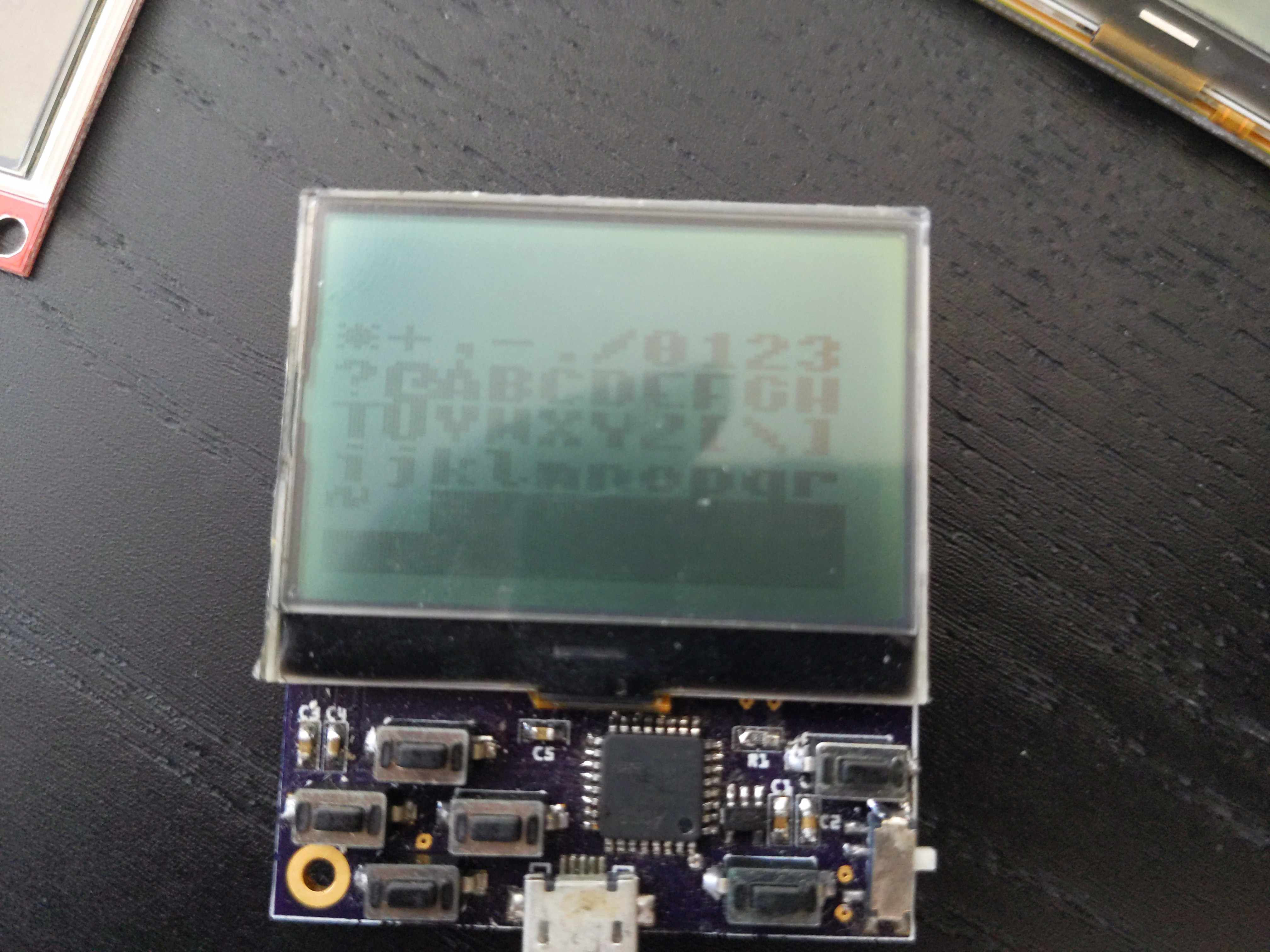
I remembered another of my experiments, when I was designing a conference badge:
![]()
I rejected that design back then, because I wanted animations, and the display was too slow to even display a bouncing ball. Plus, it was more expensive than the color TFT displays available. But for PewPew speed of the display doesn't matter as much – the games are not that fast. So if I could find a similar display, only cheaper...
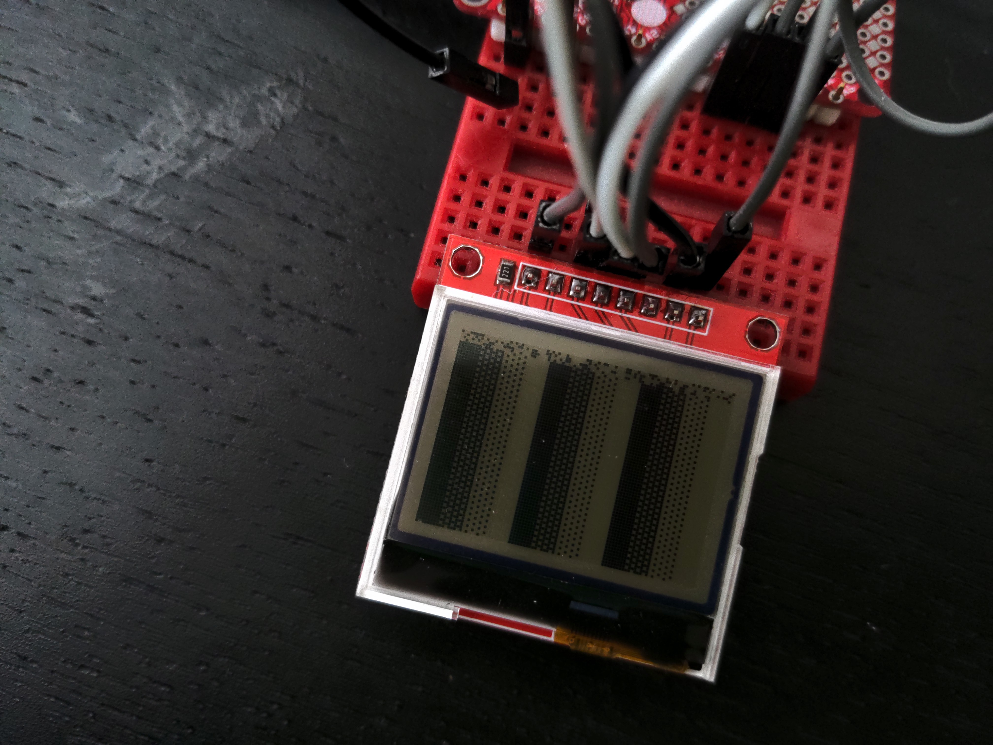
So I raided my drawers, and found this HX1230 breakout board:
![]()
Several hours of searching and detective work led me to discover that the display used here is RH-112, and that it was used in many old Nokia phones, including Nokia 1202. A quick look at Aliexpress reveals that there are lots of spare parts for those phones available, including the displays, that can be bought for $1.30 a piece. Seems like this is the perfect display fo this project, and since the displays are already produced and lie there in the storehouses, I'm actually decreasing the amount of electronic trash by using them for something more useful.
-
Why a New Design?
05/09/2022 at 17:37 • 0 commentsSo far the most successful among the PewPew family of devices has been the #PewPew Standalone – I ran many workshops with it, I sold it on Tindie, I made several badges for conferences out of it, and now @Makerfabs is selling it for general population to use. Despite being a bit clunky, it's simple and cheap and gets the job done very well. I have later experimented with other designs, adding various display screens, stronger microcontrollers, a variety of buttons and touh pads, different LEDs and recently even WiFi, but the resulting designs were inevitably more complex and more expensive. Now I feel like I can put together what I have learned through all this experimentation, and design a device that is even better for running workshops, less complex, and cheaper than the Standalone.
The problematic component is the LED matrix. Yes, it's cheap, but that's pretty much its only advantage. The original FeatherWing version used a bi-color matrix, with four possible colors. In the Standalone I replaced it with a much easier to source and to drive, and also cheaper, monochrome matrix, that is driven in the background by a special software library compiled into CircuitPython. There are no longer any colors, just shades of light, and to save pins, the same library also scans for the button presses. This leads to some visual artifacts and of course displaying text is not easy.
I have tried replacing the LED matrix with individual LEDs – either bi-color or monochrome, but while this makes the device considerably slimmer and lighter, it increases the assembly cost – with all those discrete LEDs having to be soldered.
Adding a color TFT screen required more memory and more processing power, and while the resulting device is very nice on its own, and lets you make much more advanced and nicer games, it is also more expensive and complex – not suitable for quick workshops anymore.
Finally, I was pretty happy with a monochrome OLED screen. The additional code required forced me to shrink the filesystem on the device a little bit, from 64kB to 48kB, but you can still fit all the games that have been written for the device so far on it all at once, so I don't consider it a big drawback. The screen is the wrong shape, landscape rather than square, so a lot of it is wasted, which is not great, but acceptable. The additional components required by the display, and the large number of connections of the display itself contributed to both the complexity and price, though. I tried to offset it by shedding components such as buttons, battery holder, USB socket and expansion socket with pads and cutouts in the PCB itself – and I am happy with the results – but I feel like I can do better still, with a different display.