 Joseph Marlin
One of the findings from the most recent project log, where I built a prototype of the hopper-to-feedwheel mechanism was that the system was extremely flimsy. It required a great deal of duct tape, was all out of tolerance, and all sorts of parts didn't join up right not due to improper dimensions but due to insufficient structural design.
I have now added extensive crossbracing to secure the mechanism. Part of that also included designing the cover that slides over the motor for aesthetic purposes, and I think it turned out well.

Above is a rendering of the full device so far. As you can see, I still have not redesigned the chutes that lead from the hopper to the wheels, because I can't figure out how.
But the cross bracing looks good.
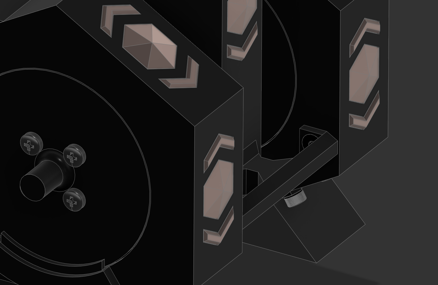
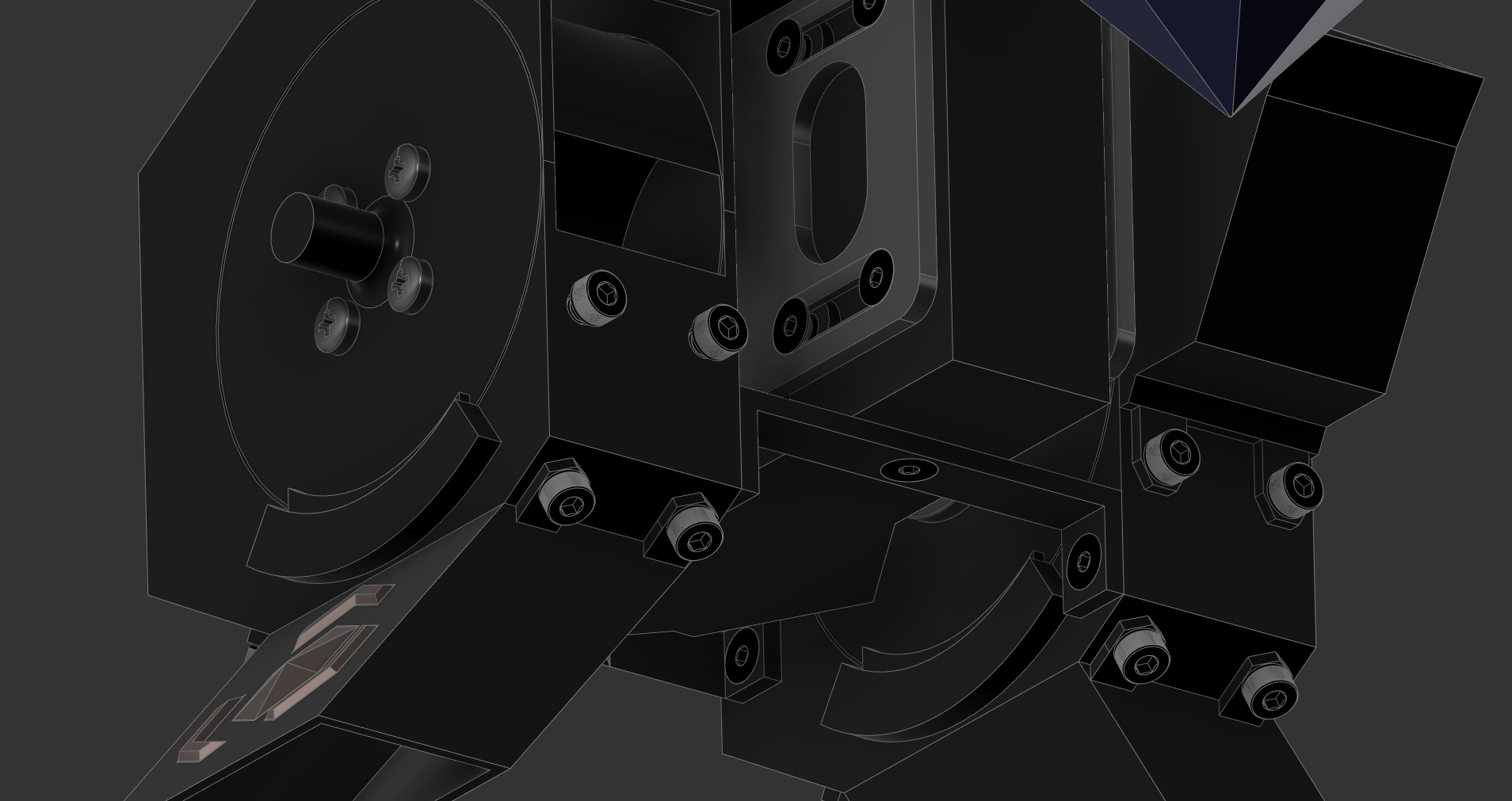
Also visible, particularly in the bottom image, are the alignment shims. These slide into their little housings and ensure the wheel stays aligned inside the wheel housing. I made the shim housing a separately printed piece with alignment holes that I will glue into place as an assembly step.
This allows me to still print the wheel housing on its side without a bunch of supports.
Next up will be dealing with the hopper-to-wheel-housing chutes.
Discussions
Become a Hackaday.io Member
Create an account to leave a comment. Already have an account? Log In.