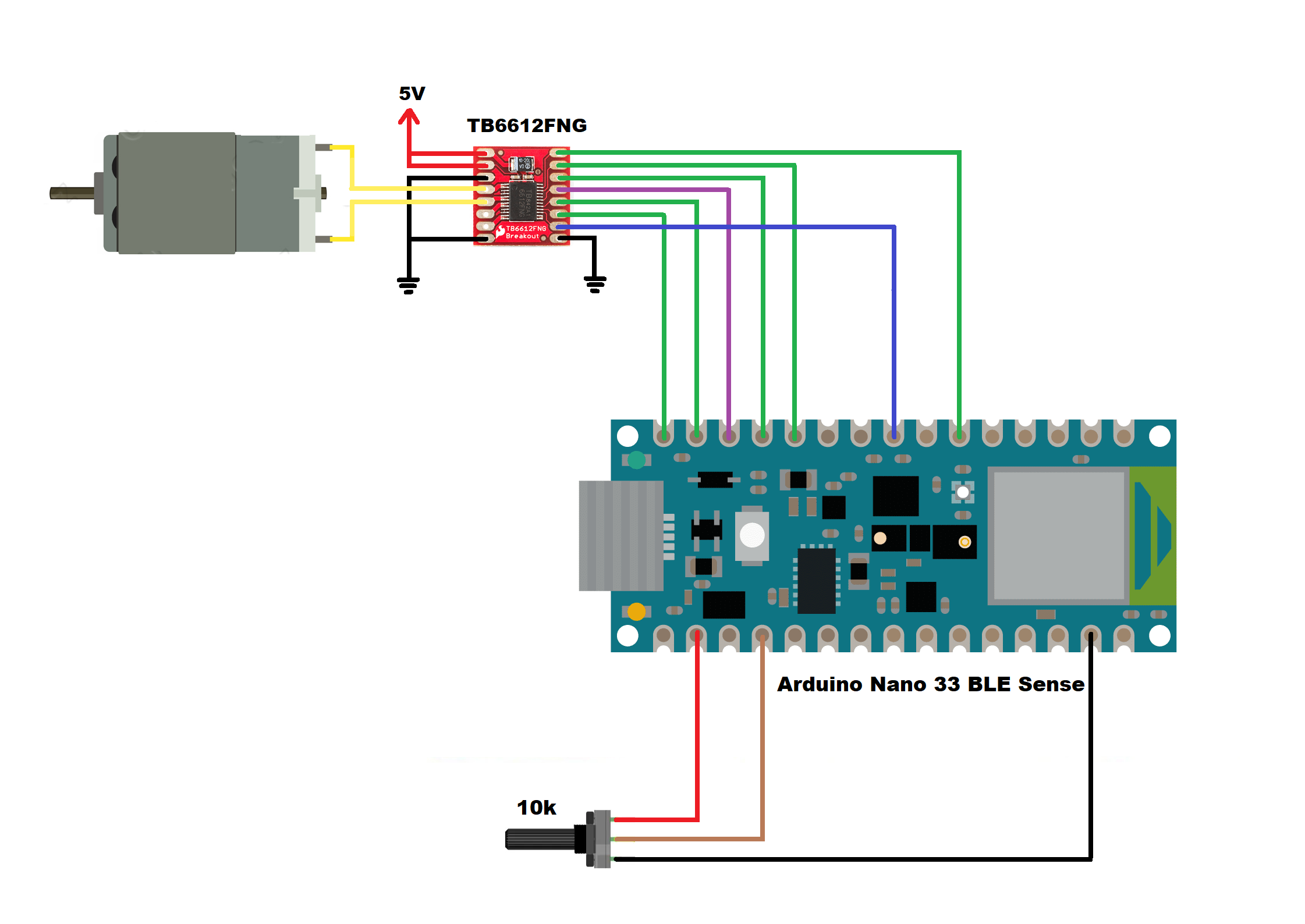
As part of the hardware updates, I have re-designed my project and in the image below I show you the schematic diagram of the speed control.

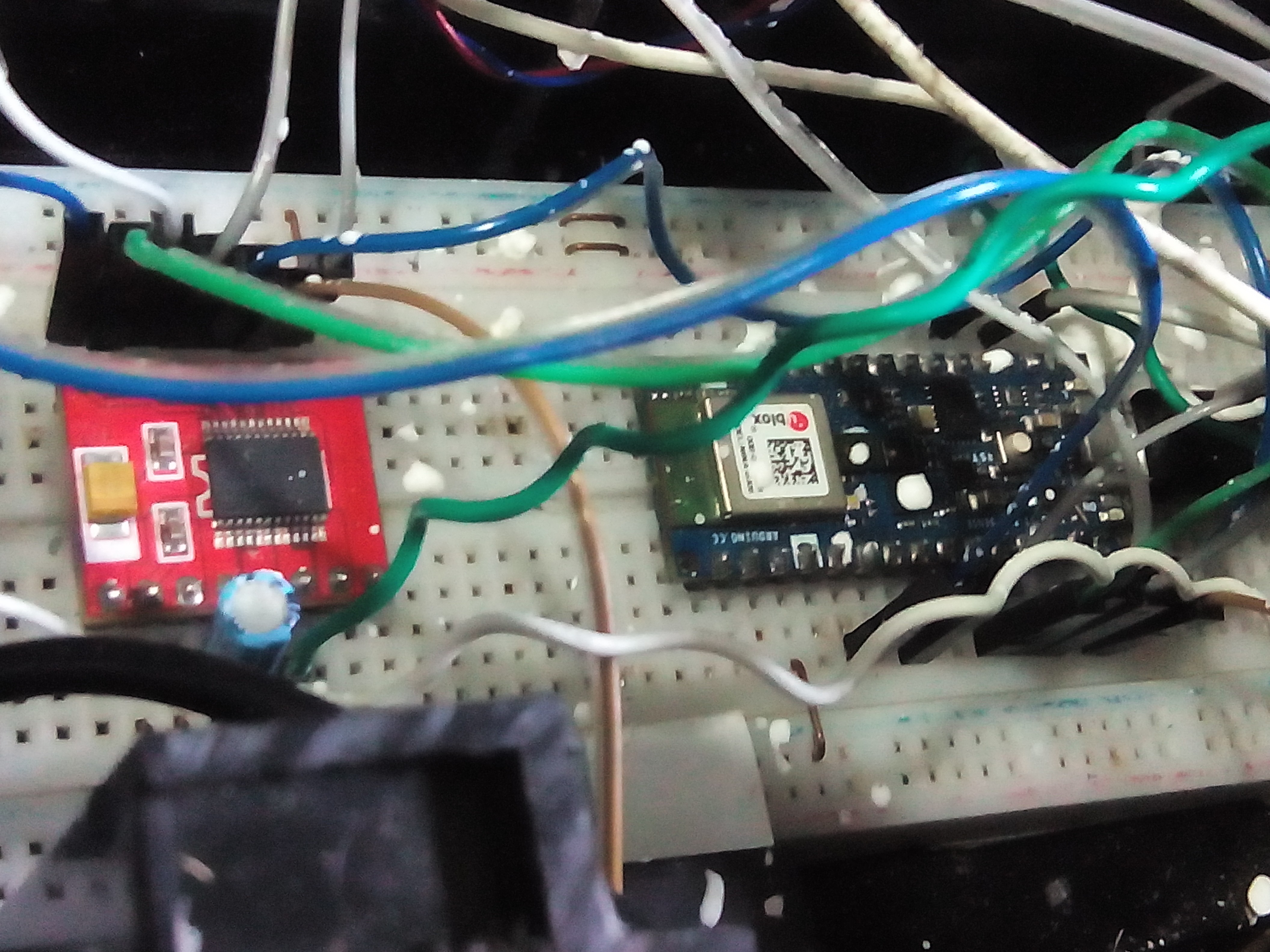
Below I show you an image of these devices.

In this way I optimized the spaces, and the energy consumption is lower with this Arduino Nano 33 BLE Sense board. Next I show you the code.
speed_control.ino
//AUTHOR: GUILLERMO PEREZ GUILLEN

#define POT A0  // Pot 10k
int raw_pot; // Store value of the pot
int duty;   // duty cycle - PWM

int STBY = 10;        // standby pin
// motor A
int PWMA = 3;        // velocity
int ain1 = 9;
int ain2 = 8;
// motor B
int PWMB = 5;        // velocity
int bin1 = 11;
int bin2 = 12;

void setup(){
  pinMode(STBY, OUTPUT);
  pinMode(PWMA, OUTPUT);
  pinMode(ain1, OUTPUT);
  pinMode(ain2, OUTPUT);
  pinMode(PWMB, OUTPUT);
  pinMode(bin1, OUTPUT);
  pinMode(bin2, OUTPUT);
}

void loop(){
  raw_pot = analogRead(POT);
  duty = map(raw_pot, 0, 1023, 0, 255); // range vaalue from 0-255

  mover(1, duty, 1);                                // motor 1, velocity, forward
  mover(2, duty, 1);                                // motor 2, velocity, forward
  delay(50);                                        // 50 ms
}
void mover(int motor, int velocidad, int direccion){    //Let's define the move function,                                                                                            a acciona un motor, fijar su velocidad y el                                                                                            sentido de giro. Definimos:    //motor:                                                                                                    llamaremos 1 al motor A, y 2 al motor B
                                                        //velocity: from 0 to 255
                                                        //direction: 0 for clockwise, 1 for counter-clock wise
digitalWrite(STBY, HIGH);          //disable standby to move
 boolean inPin1 = LOW;             // we create the boolean variable (it can only be HIGH/LOW) inpin1
 boolean inPin2 = HIGH;             // and we assign the value LOW. To inPin2 we give the value                                                                HIGH
if(direccion == 1){
inPin1 = HIGH;
inPin2 = LOW;
}
if(motor == 1){
digitalWrite(ain1, inPin1);
digitalWrite(ain2, inPin2);
 analogWrite(PWMA, velocidad);
  }else{
    digitalWrite(bin1, inPin1);
    digitalWrite(bin2, inPin2);
    analogWrite(PWMB, velocidad);
  }
}
void stop(){                           // standby action
  digitalWrite(STBY, LOW);
}
 Guillermo Perez Guillen
Discussions
Become a Hackaday.io Member
Create an account to leave a comment. Already have an account? Log In.