DeepSOIC
-
Magnet + magnetizer coil = loudspeaker
06/22/2017 at 22:11 • 0 commentsNow that I've made a magnet using the coil, the magnetic field is just right to create a loudspeaker using that very coil as a voice coil. Cool, isn't it?
-
more magnetic = more better
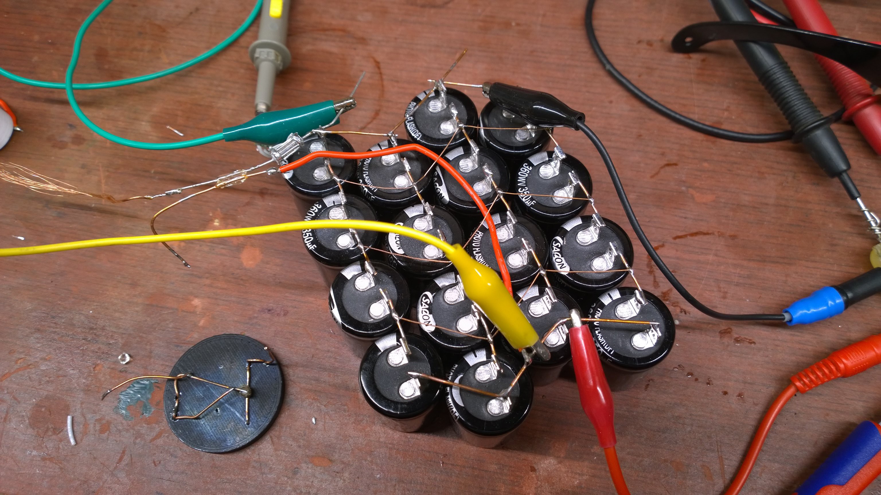
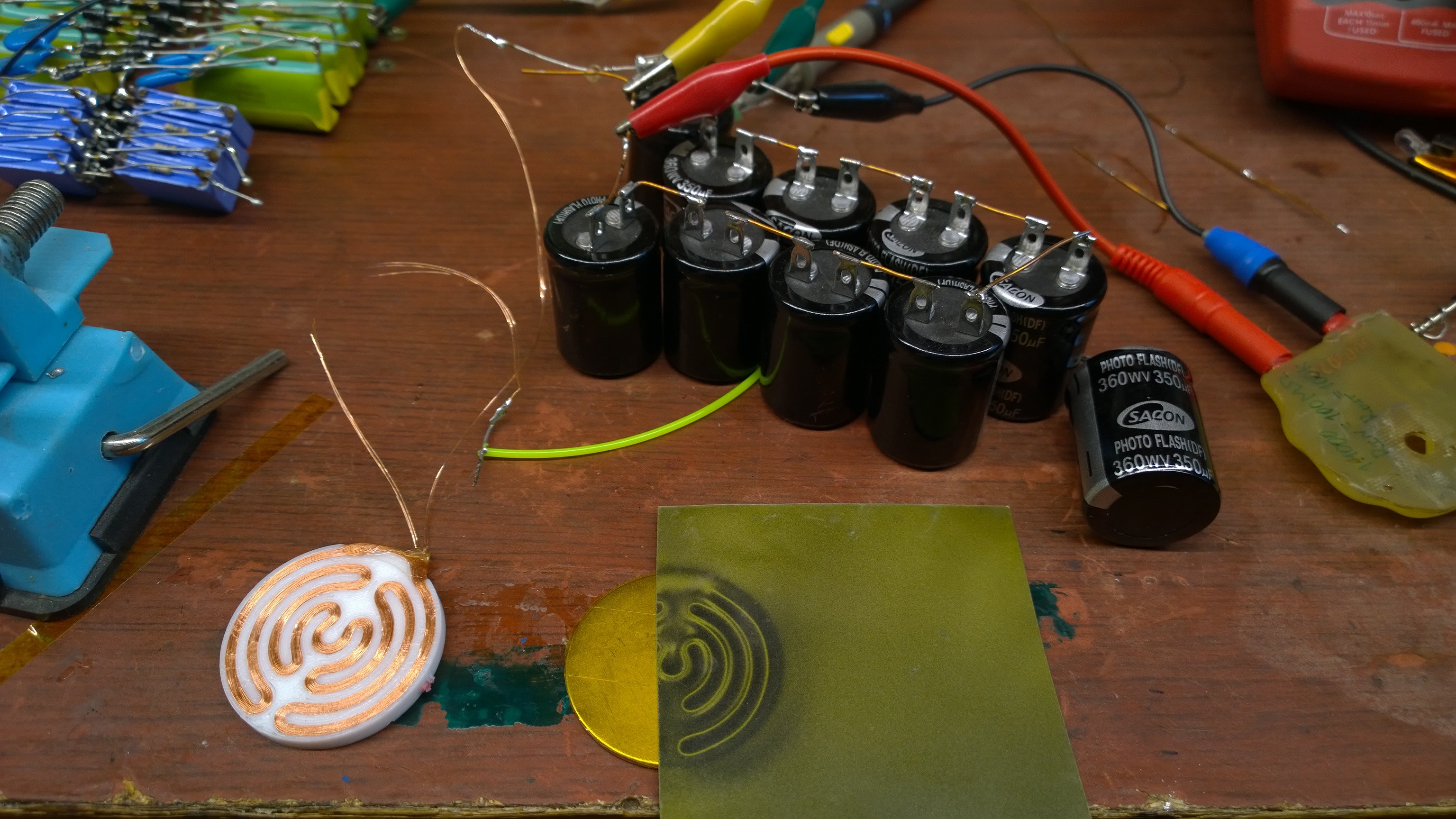
06/18/2017 at 20:43 • 0 commentsAll my good caps in one big bank. Sixteen 350uF caps charged to 330V each, with total voltage of 1.3 kV, and stored energy of about 300 J.
![]()
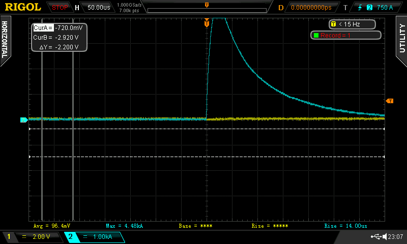
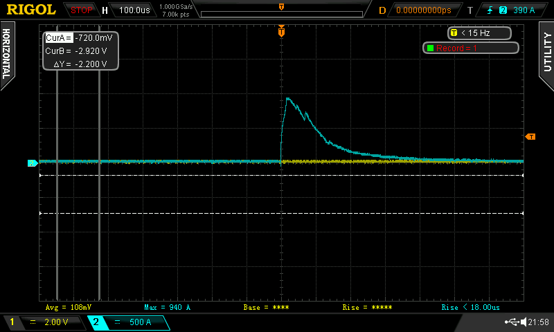
Discharged into a coil - 4 loops of 15-strand 0.17 mmdia magnet wire, R = 0.13 ohm, 4 uH. Which made a pulse of current of about 4.5 kA peak.
![]()
which develped about 45 V across my home-made abuse-proof 10 mOhm resistor.
The coil survived, but it was close. PLA plate has cracked because of coil self-repulsion. Most likely it was its last pulse.
![]()
and the magnet is beautiful. It feels very strong. It is just a tiny bit not strong enough to levitate graphite. I think I am very close to full magnetization of the material.
![]()
I made a small switch using salvaged contact bumps from a fridge thermostat relay. The switch made a very loud bang, and welded closed. I can't separate it. I need more robust contacts.
![]()
-
capacitor problems
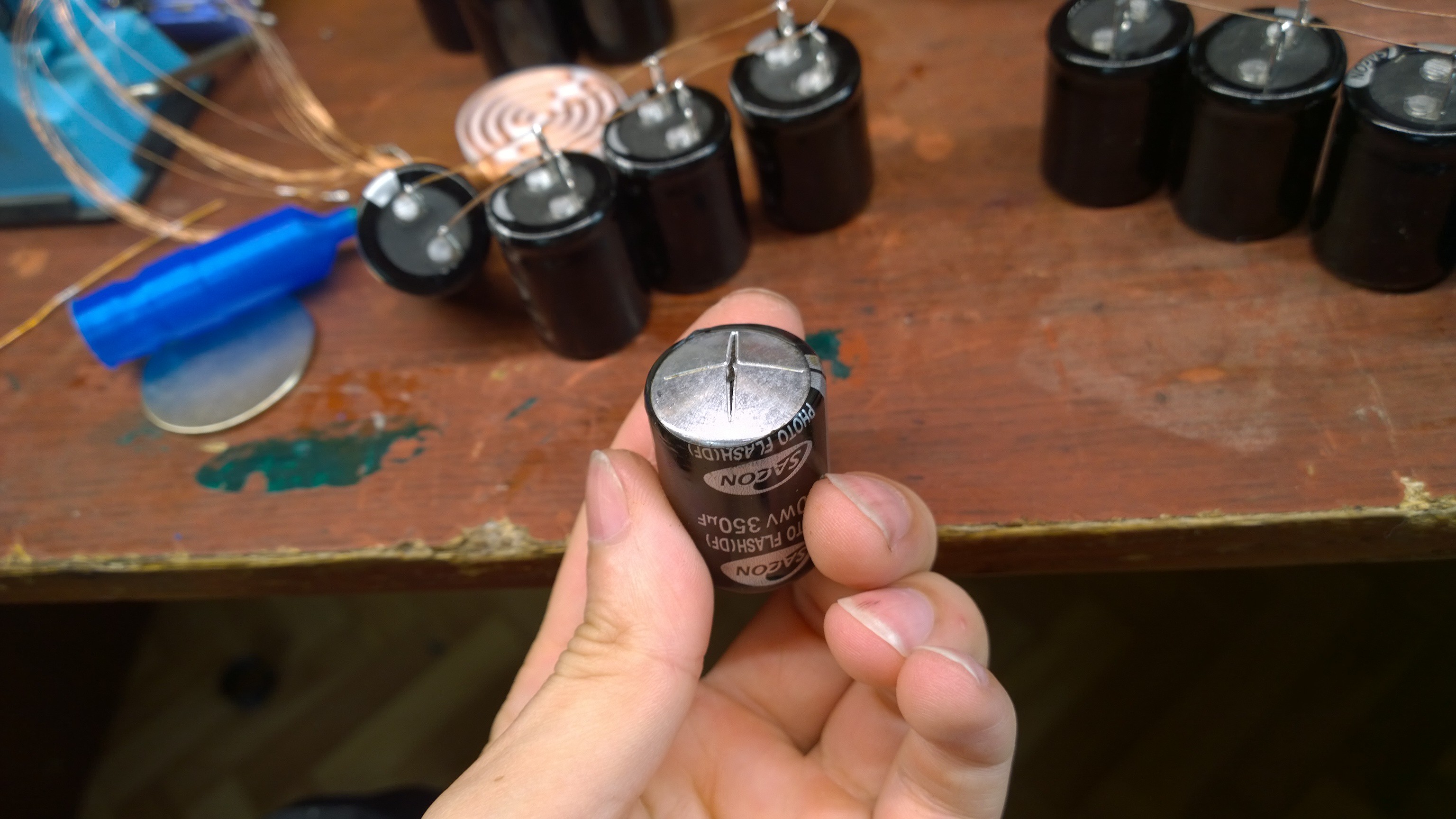
06/18/2017 at 16:09 • 0 commentsThe capacitors I bought for this project are shit.
They are SACON photo-flash electrolytic, rated for 350 uF 360 WV (WV == working voltage, AFAIK). When I charge one up (new capacitor!), it starts to seriously leak above about 250V. Which is a problem, because if some capacitors are leaking and others aren't, substantial charge imbalance in series connection can build up. This can cause low-leakage "cells" to charge up to more than rated voltage. And when the bank is discharged, leaky capacitors will end up with reversed polarity charge, which is very bad for their health.
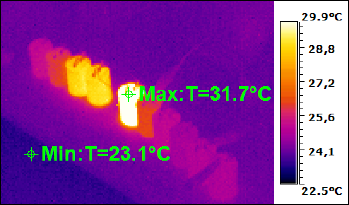
It seems that if I let the leaky capacitors leak for a while, the leak diminishes. So I've set up a "conditioning" process. I just soldered a few caps in parallel, and connected them via a rectifier to a variac, so that they are held at their rated voltage of 360 V till the leak disappears. The remaining leakage can be easily seen with thermal camera.
![]()
This is a thermal camera shot of the capacitors in about 2 minutes after the voltage was applied.
![]()
Their temperatures are reasonably even, apart from one cap, which I think I had conditioned previously already, I just forgot which one so I just soldered it into the bank.
About 20 minutes later, I was wasting time in front of computer, when I heard the variac started roaring because of load current increasing. I rushed to switch it off, but before I did that, a bang happened. One capacitor has vented. It turned out, these capacitors contain a cloud worth of magic smoke! It all happened within 2 seconds I think. Luckily I was right next to it all to switch it off promptly, otherwise it might have resulted in a fire.
![]()
![]()
Continuing the conditioning...
![]()
most caps seem to be doing well, apart from three. Strangely they are right next to the one that vented. I think they might have been upset by the heat from that faulty one.
-
chooch factor overflow
06/17/2017 at 18:00 • 0 comments2kv pulse was all-right. 3 kV... BANG!
![]()
That was a hell of a bang. It's ringing in my ears =( . I should wear headphones next time.
I happened to have recorded the current pulse. I don't think it is useful for something, but here it is:
![]()
-
complex shape coil
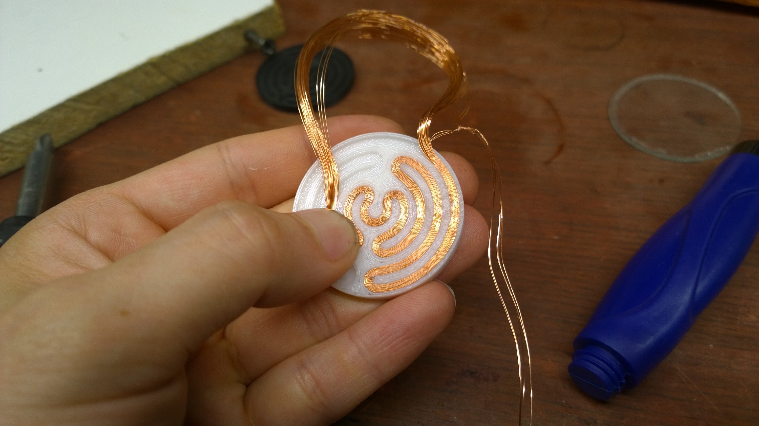
06/17/2017 at 17:11 • 0 commentsYay! I just had success with impriting a more-or-less complex pattern into the magnet.
Making the coil wasn't fun though.
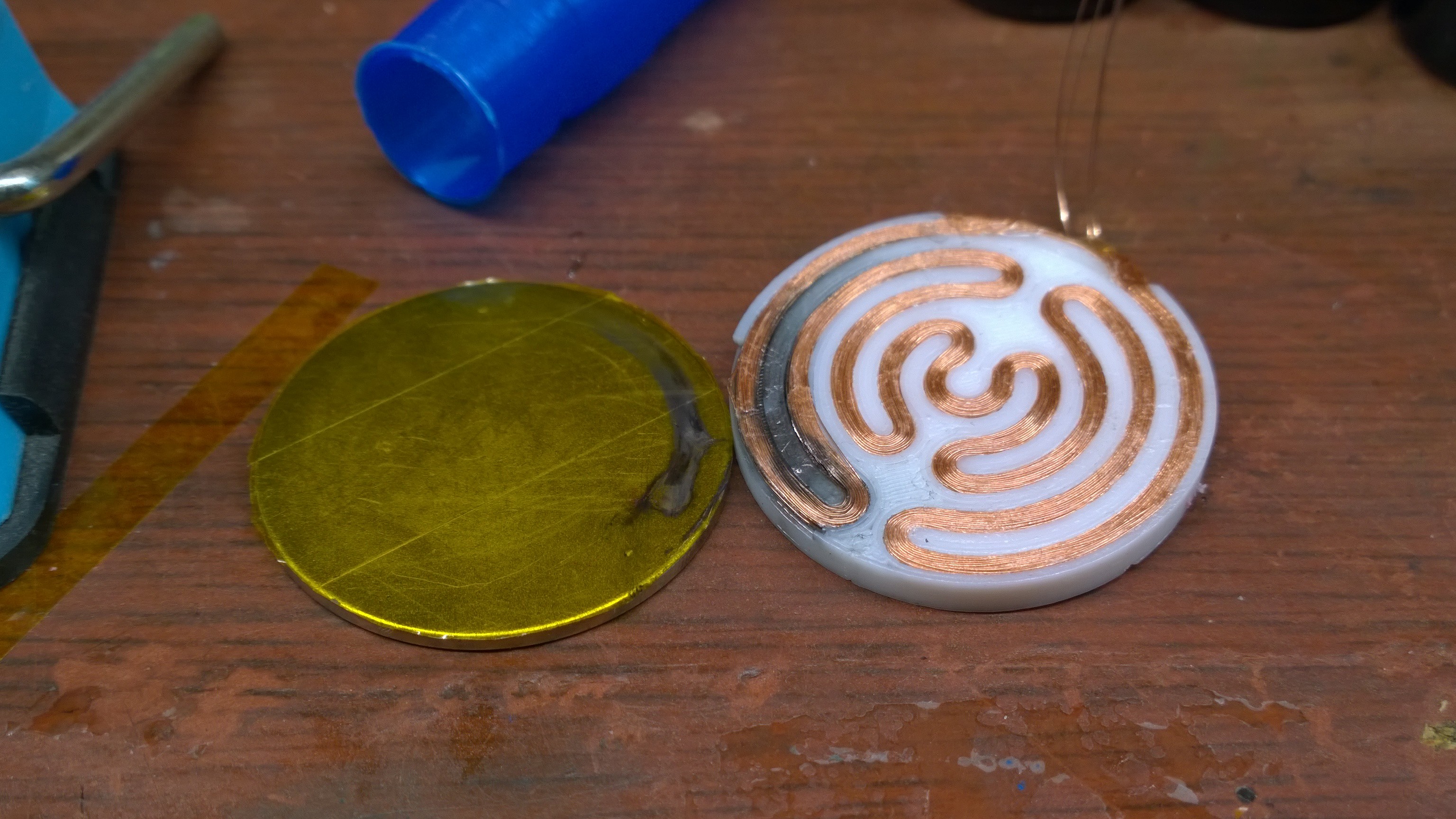
![]()
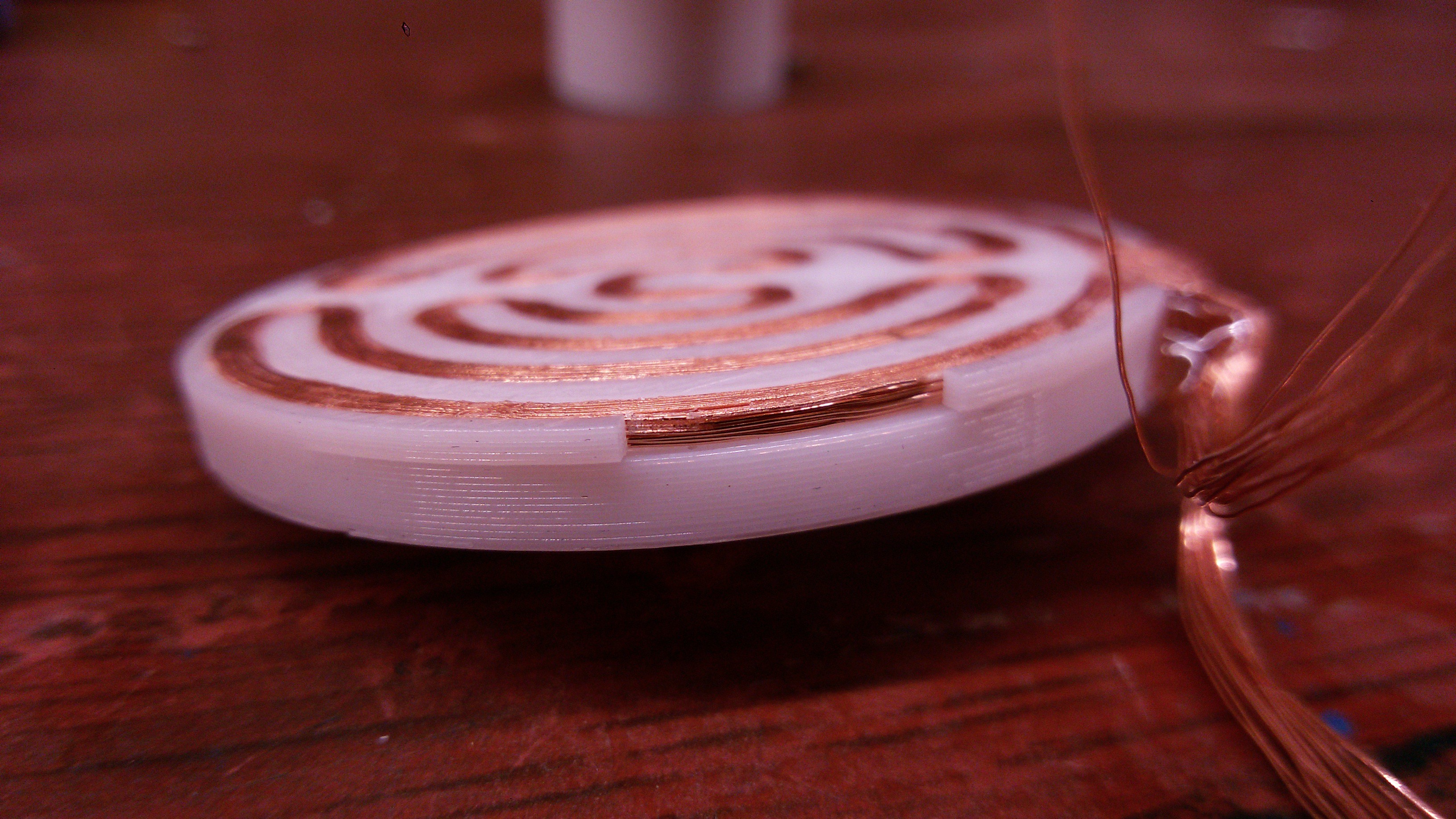
I 3d-printed a plate with a channel for the coil. Then I wound a coil of right length between two screws, and packed it into the channel. It went like 1) pack a small piece; 2) put some superglue, and push on top with polyethylene bag... repeat till done. Very annoying!
But the results were worth it!
![]()
The coil measures 2.43 Ohm, 73 uH, and has 20 loops (turns). It took a pulse of about 500 A to get appreciable magnetization. The capacitor bank was charged to 2 kV. It was ridiculously dangerous. And unfortunately, I want more!!
-
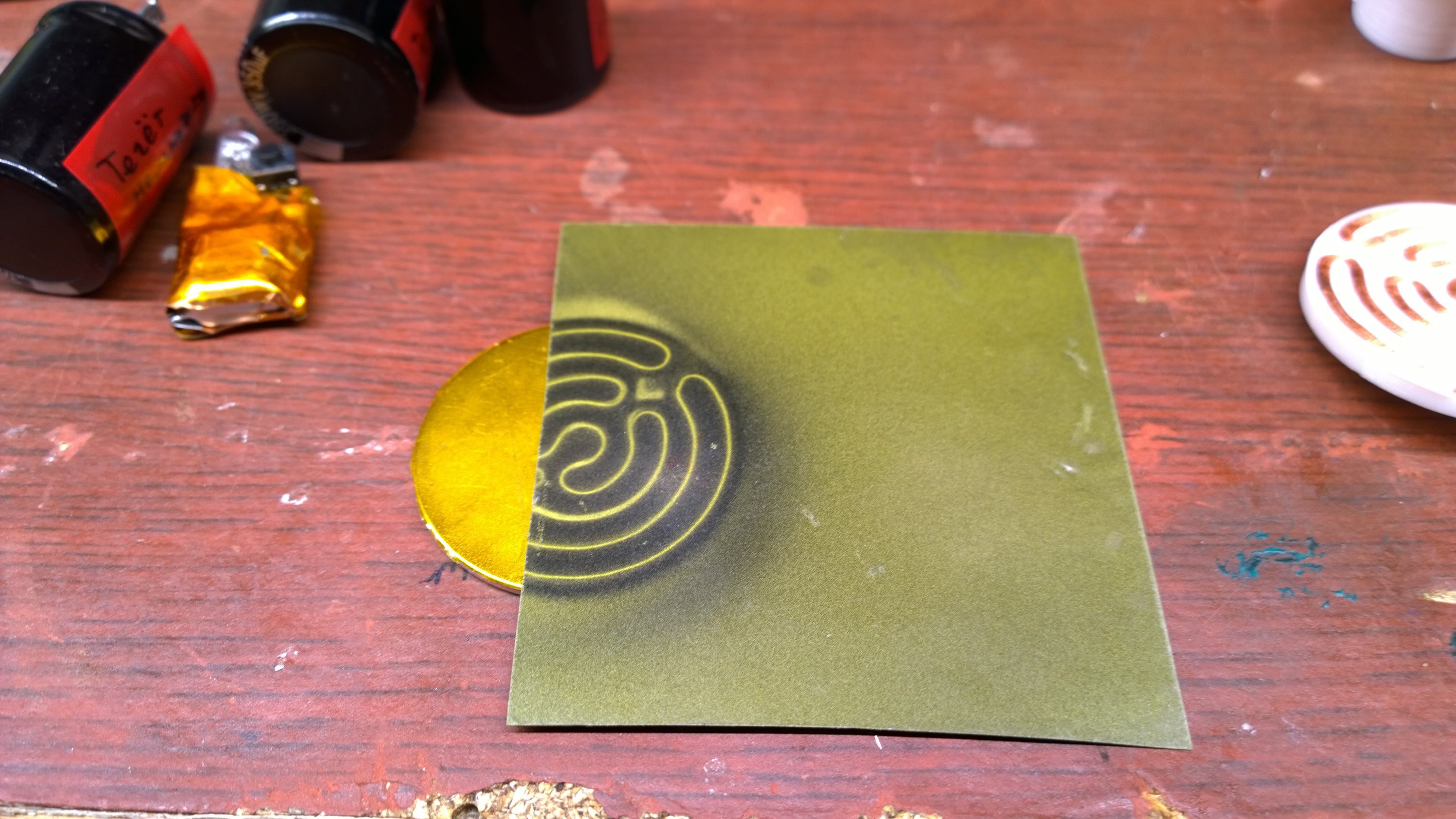
Having fun! Doodling on a magnet =)
06/09/2017 at 00:04 • 2 comments -
Catastrophic failure of a coil
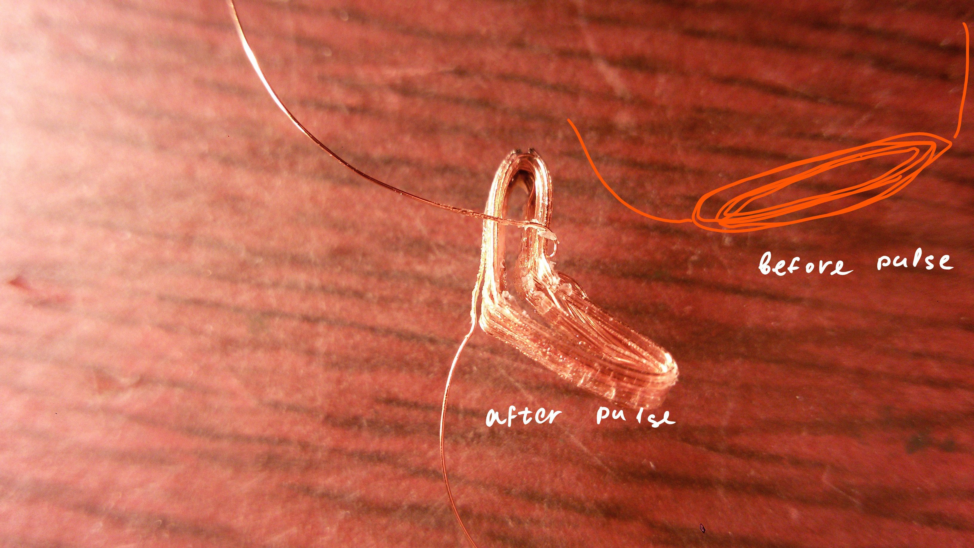
11/28/2016 at 00:13 • 0 commentsSo I wound a rough representation of a coil I want to use to magnetize the ultimate goal magnet.
The first one was wound on a lamination plate from some transformer. When I connected it to capacitor, a loud bang followed. The insulation of wire failed, causing a dead short in the coil.
Then I wound another one. I removed it from the carrier, and wicked with superglue to hold it together. When I pulsed it, agan a loud bang followed.
Then I noticed that the coil looks a bit odd. OK, ripped apart by magnetic field. And only after careful investigation I realized how much did it actually deform. The places where there were sharp bends were straightened out, and new bends were created where the coil was straight. Wow, that was quite some force!
![]()
-
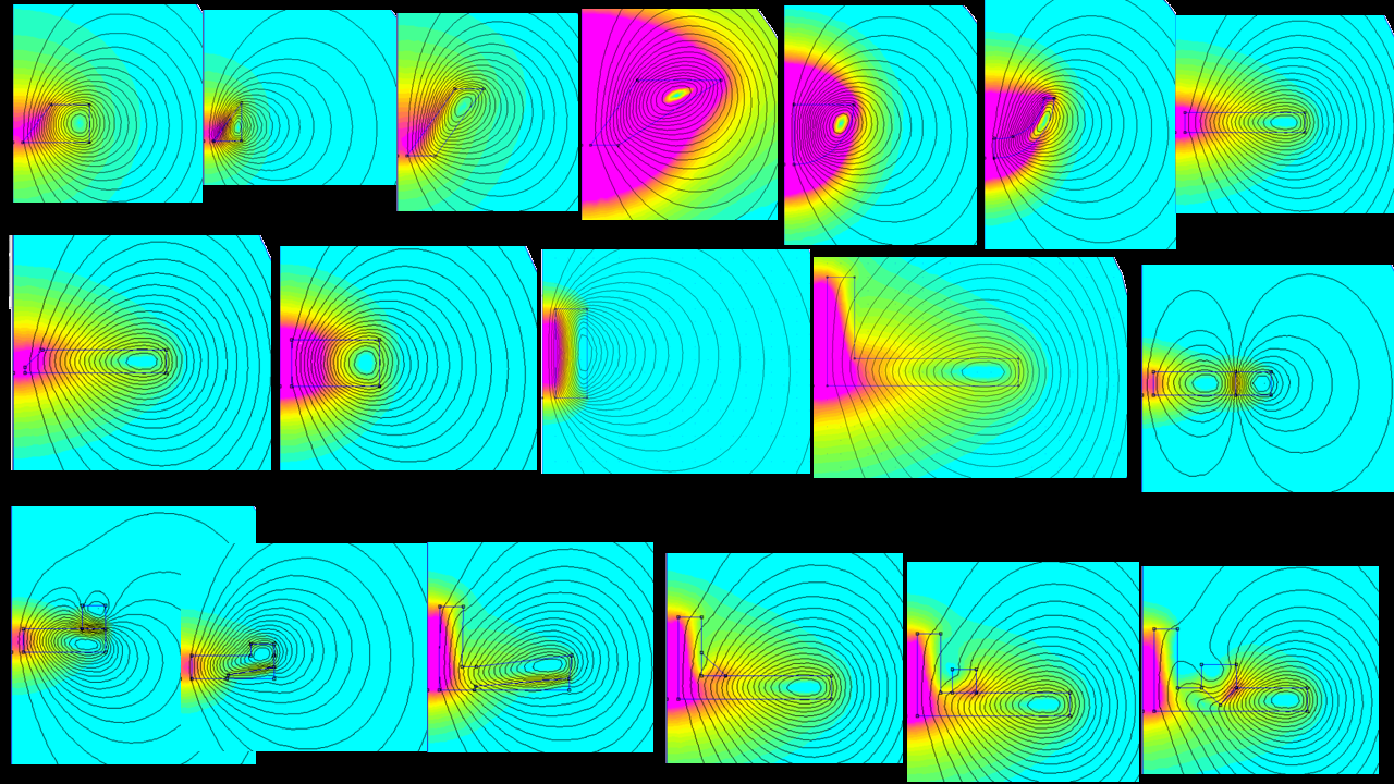
Quest to coil shape
11/27/2016 at 14:49 • 0 commentsI did a bit of FEMM trial-and-error way to find a good pixel-making coil.
![]()
None of the configurations I've tried so far is satisfactory, so I'm afraid I have to abandon CNC approach, and make coils specific to the magnetizaion pattern I want to make.
-
FEMM again
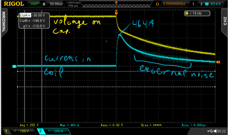
11/26/2016 at 21:23 • 0 commentsNow, I have measured the pulse I used to create the pixel.
Capacitor 350V 220 uF was discharged into the coil.
![]()
464 A peak current.
Then I measured the size of coil, and unwound it to count the number of turns.
R = 0.5 Ohm
thickness 2.4 mm
inner d 1 mm
outer d 3.2 mm
top dia 2.2 mm
cross section area (approx) 2.0 mm2
N turns = 50=> average current density in coil = 11600 MA/m^2
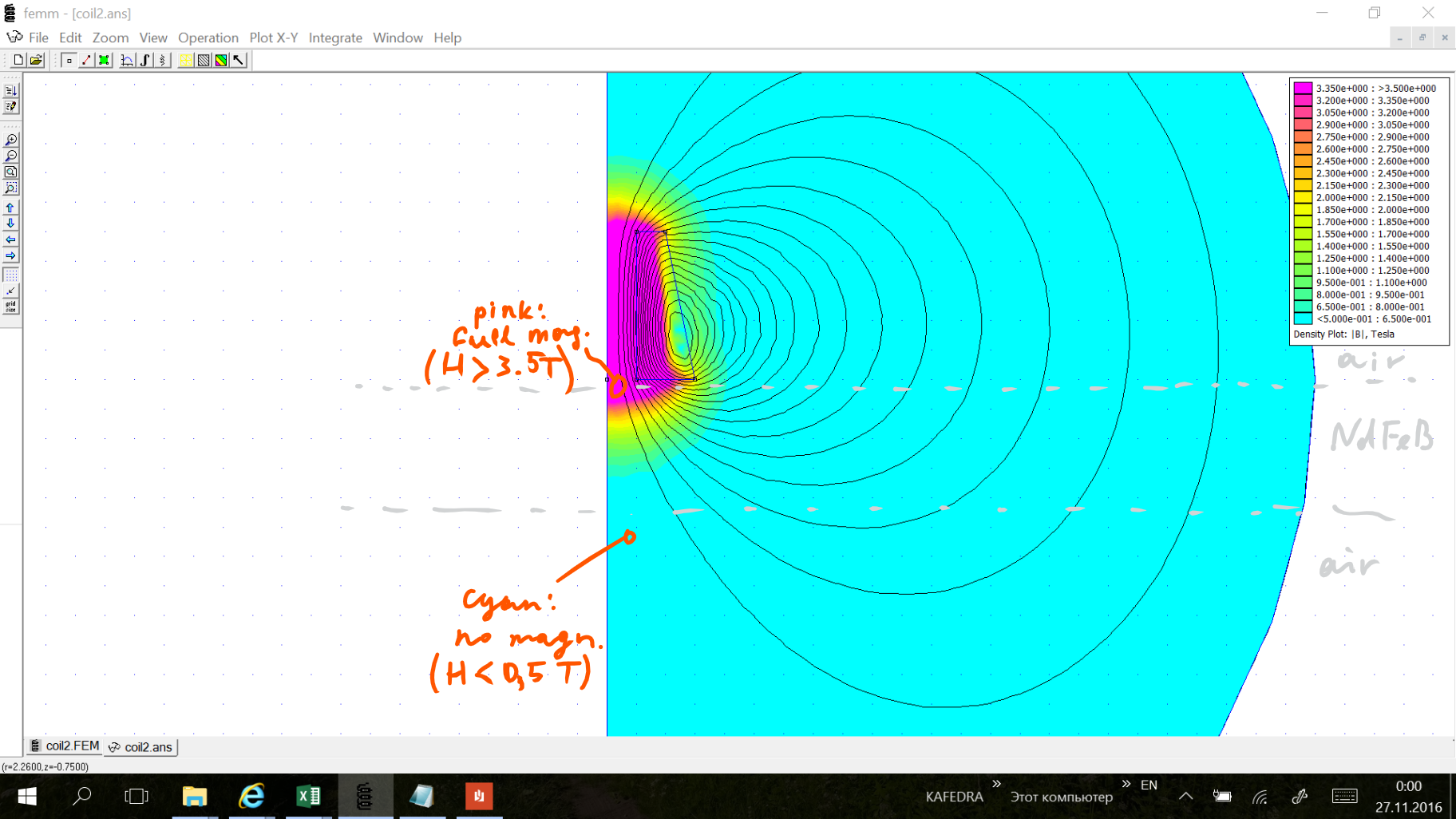
FEMM results
![]()
On this picture, I've set up color plot to span a range 0.5-3.5T. This range corresponds to magnetic field required to magnetize NdFeB: 0.5 is about where it starts to magnetize, and 3.5 is to achieve saturation.
I've taken these values from http://dx.doi.org/10.3989/cyv.2005.v44.i3.385
This isn't particularly correct, because magnetization affects magnetic field, and that can change what is actually magnetized. But I don't know how to simulate the process properly, so I'll stick to simple treatment for now.
-
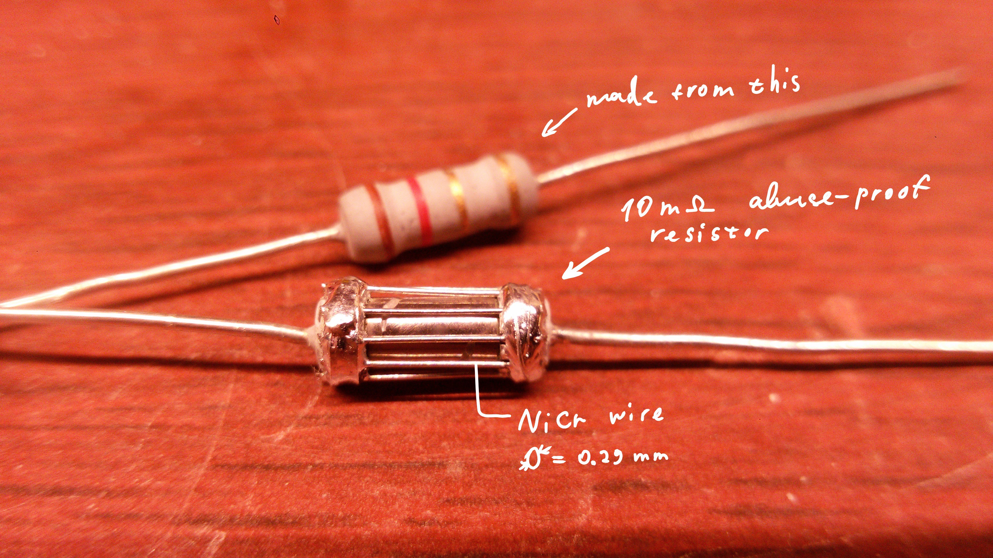
Replacement for blown resistor
11/26/2016 at 18:56 • 0 commentsMade my own resistor.
![]()
I feel I'm crazy. I'm making my own resistors!
(re)Mangetizing neodymium magnets
My attempts at replicating what Polymagnet are doing