DeepSOIC
-
Fun with FEMM
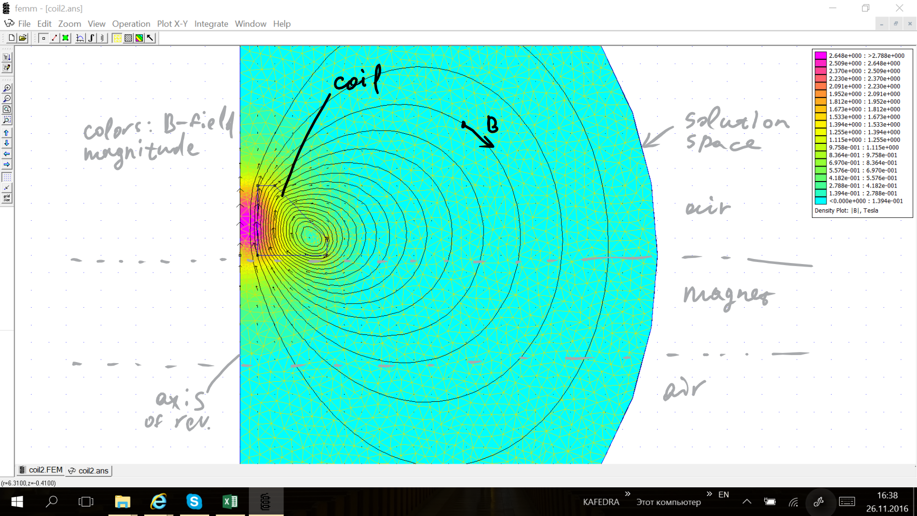
11/26/2016 at 13:51 • 0 commentsI'm starting to optimize geometry of the coil for best magnetization.
The aim is to attempt to focus the magnetic field into a sort of a beam that penetrates the magnet as deeply as possible. I want to localize magnetization zone, so that I create as little tangential magnetization as possible.
So far, I just simulated the approximate geometry of the coil I used to create that "pixel".
![]()
The side of the coil creates a strong tangential field, which is something undesirable. On the top side, the field has slightly better shape, but is much weaker.
-
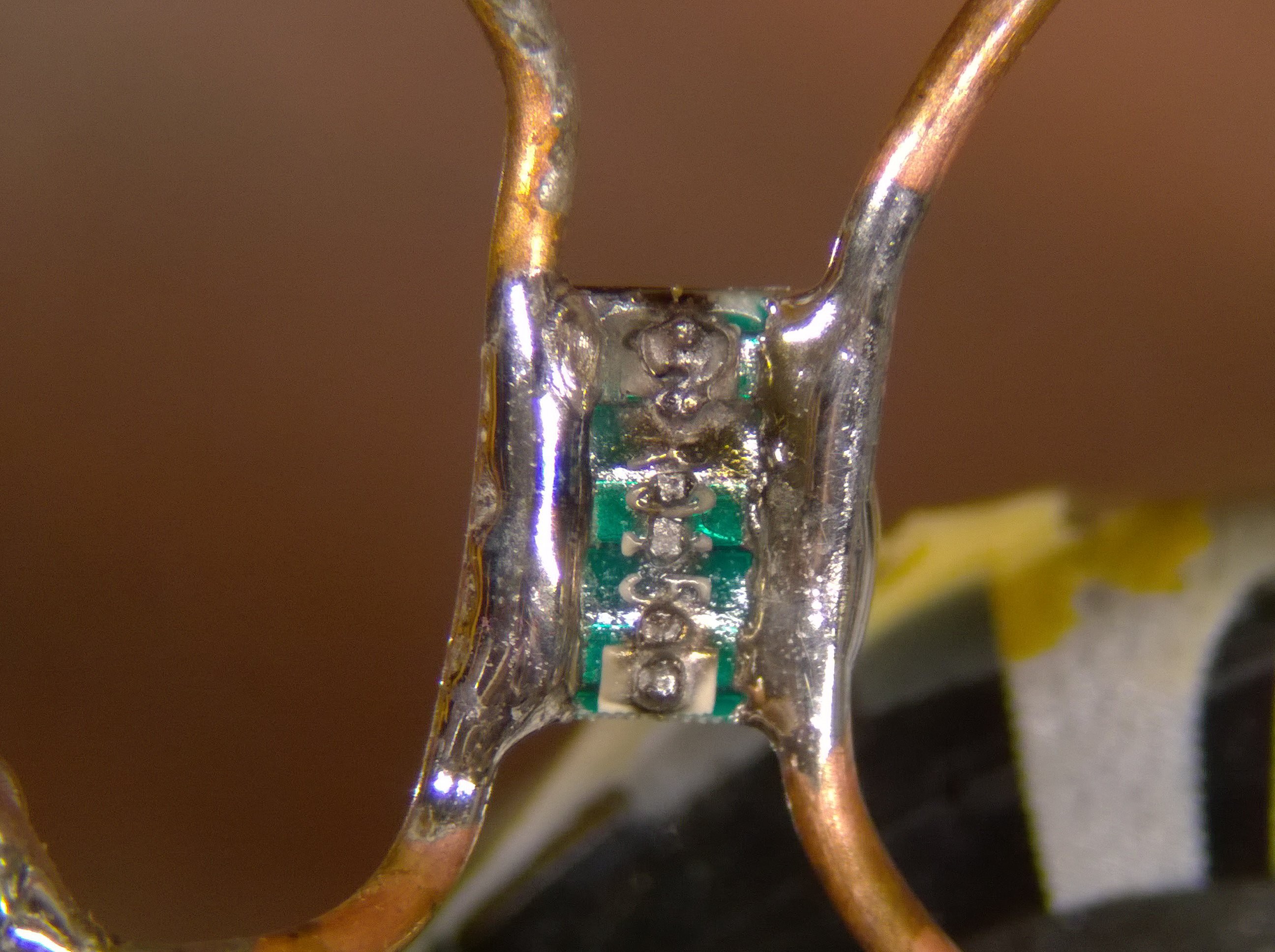
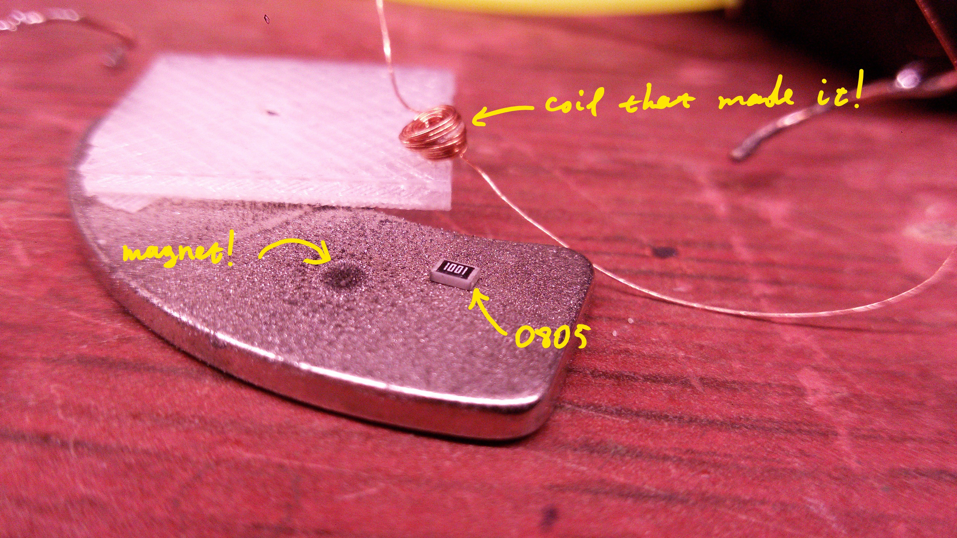
More success! Magnetic pixel.
11/25/2016 at 22:49 • 0 commentsYessssssssss, getting there!
![]()
I created a small magnetization spot on a big magnet! With appreciable strength! That is an epic success!
(To make it visible, I ground some steel over that magnet.)
-
Success!
11/25/2016 at 19:14 • 2 commentsI doubled the capacitance, and the re-magnetized ball is just a little bit weaker than the rest.
I actually didn't really expect this. I thought I have more than enough capacitance to achieve the maximum peak current. So I think, what might be happening is that it takes time to magnetize the magnet.
I also tried to replace a current sense resistor with a current transformer. Unfortunately, it doesn't quite work. The waveform looks like chopped off, I think this is due to core saturation. So I'm still searching for a reliable way to monitor the current.
Sorry, no pictures now.
UPDATE: then I doubled the voltage. Fired. The magnet is now indistinguishable from the rest. Brilliant! but, the coil broke. Not the coil itself, just the plastic bobbin. And the coil gets really hot after a pulse now.
The big harddisk magnet is much harder to magnetize. With this new 1640 uF 200V pulse, it gets only a slight magnetization. That will take quite a bit more engineering to magnetize completely.
-
Failure analysis (ohm's law rehabilitated)
11/24/2016 at 23:06 • 2 commentsAs I wrote in previous log, the current in the first attempt was way lower than I expected. I want to investigate, what actually happens, so that I can predict the outcome next time.
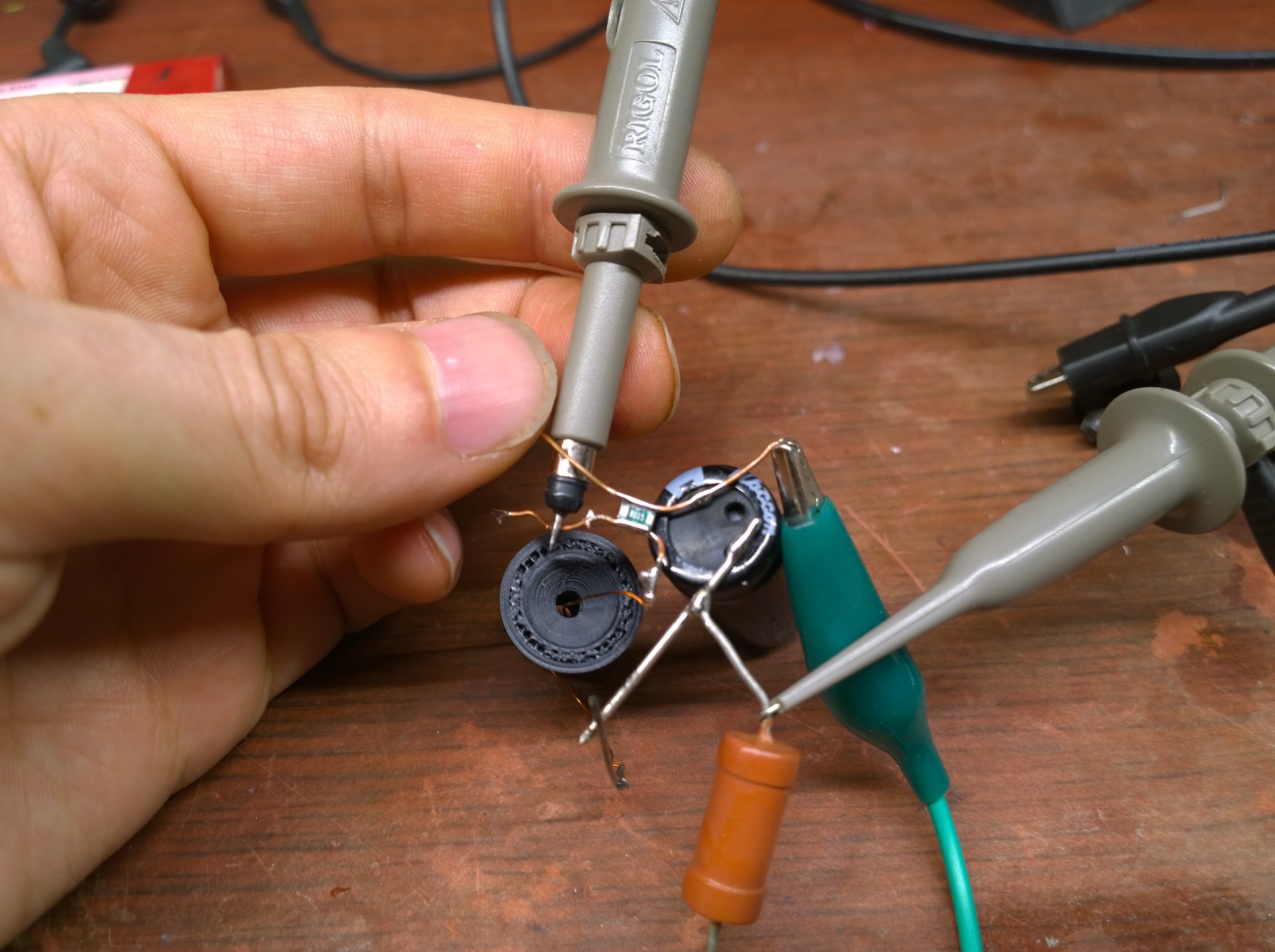
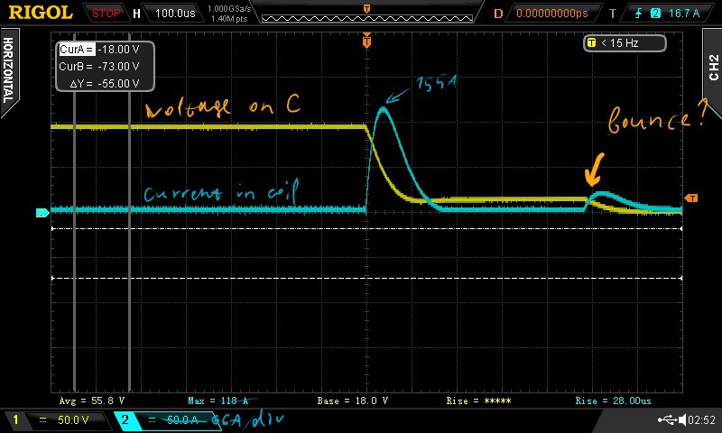
I've added a current shunt resistor (0.015 ohm, should not affect the circuit). And captured both current and voltage traces of the pulse.
![]()
![]()
Turns out my quick estimate of 80 A was way off. The actual peak current was 150 A, which is only two times lower than 300 A I wanted.
That is of course assuming the shunt resistor is accurate at currents this high. Which I'm not really sure about, but I hope that's the best resistor for the purpose, on account of being small, and its resistive layer being very very thin.
Is this waveform as one would expect? Not sure yet, maybe it's time to add some SPICE to the meal =)
UPDATE:
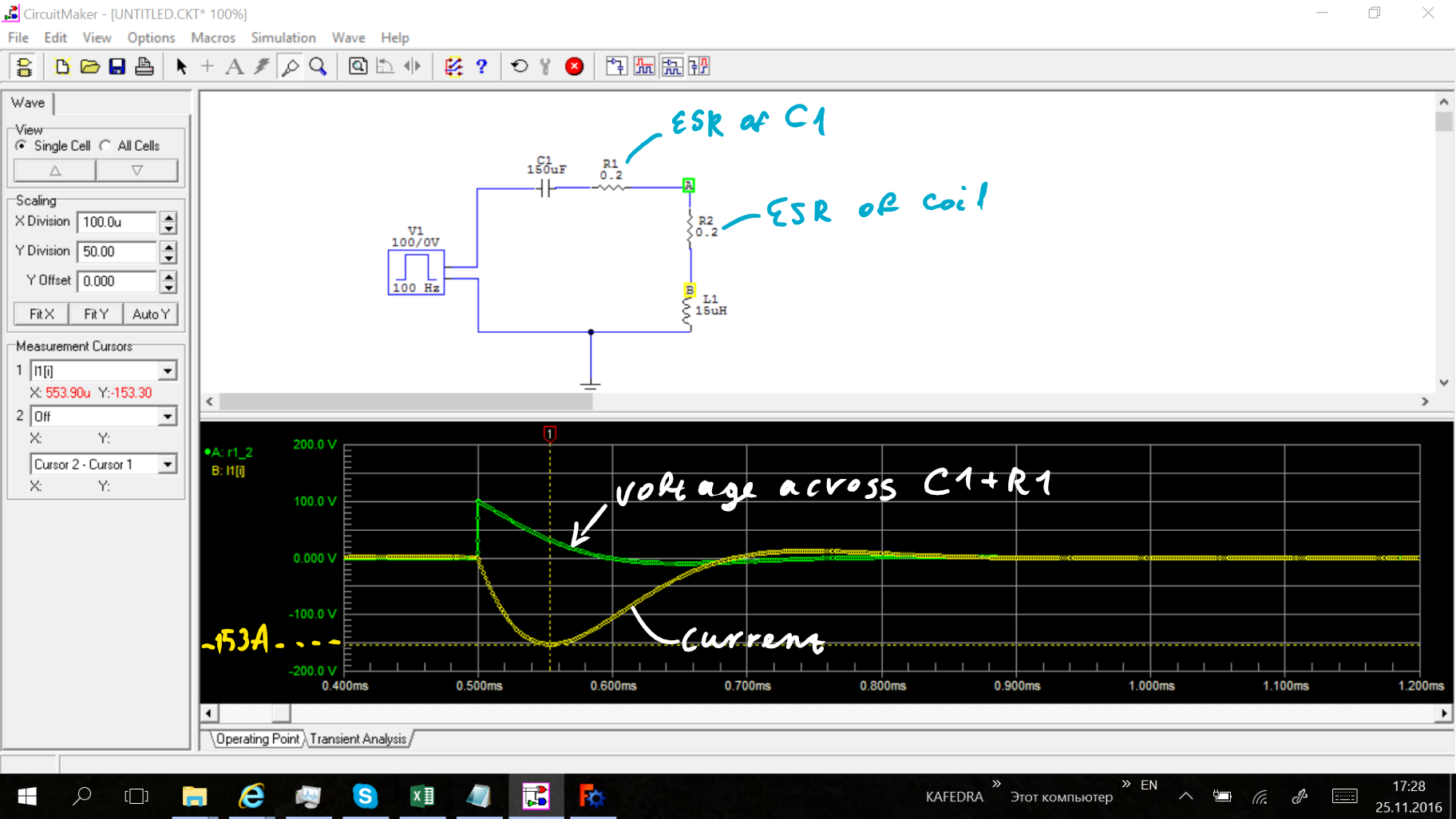
![]() Wow, that is almost spot on!
Wow, that is almost spot on!I didn't know the ESR of capacitor, so I just gave it a guess to be 0.2 ohms. The simulation waveforms are very similar to the ones I measured.
So, THERE'S NOTHING WRONG WITH OHM'S LAW. "The problem was between driver seat and steering wheel".
UPDATE2:
I tried to acquire the pulse with larger capacitor, but current sense resistor exploded. Oops.
![]()
Does it still obey Ohm's law? =)
-
The faulty Ohm's law
11/24/2016 at 21:22 • 5 commentsWe all know Ohm's law is not really a law. It's just a definition of the term "resistance", and a statement that for many things, mostly for things made of metal, the electric current is proportional to applied voltage for some range of voltage/current.
I assumed it should hold pretty good for copper conductors.. Sooo wrong!
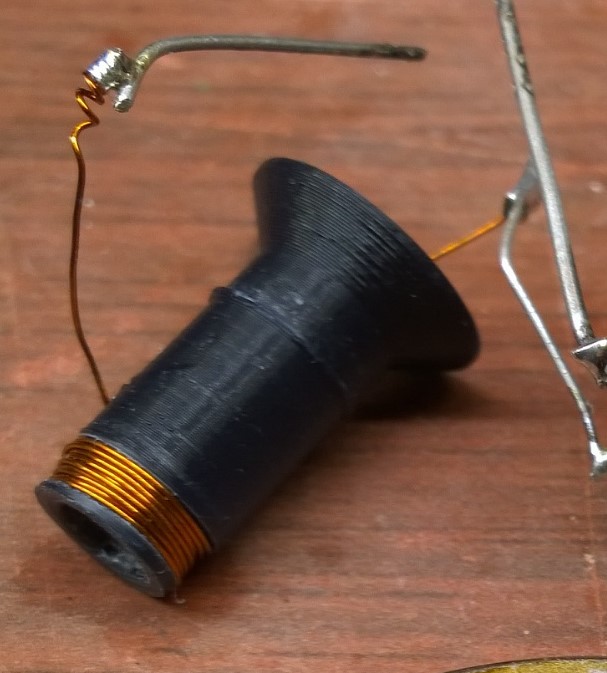
I wound a coil. Measured its inductance and DC resistance.
![]()
Inductance is 15 uH. R = 0.2 Ohms. Number of turns = 35, wire diameter 0.33 mm.
Then, I estimated the amount of current it should take to achieve a magnetic field of about 1-2 teslas inside. 300 A. So, all I need is a voltage of 60 V. Too easy....
So I dug out a photo flash capacitor (150 uF 300 V electrolytic). Charged it up to 100 V... Boom! and, nothing. No effect on the magnet.
-----
Why?
I hooked an oscilloscope across the capacitor, to see that it took more than 50 us for the capacitor to discharge. That means the discharge current is only about 80 A. That's more than 3 times less than I expected.
I was afraid that the internal resistance of the capacitor can be a problem. But from the oscilloscope trace, it was clear that the resistance is actually in the coil. WTF?
Skin effect maybe? 50 us -> kinda 20kHz frequency. Looking up skin depth on Wikipedia -> about 0.5 mm. The wire radius is only 0.15 mm, so skin effect should only slightly affect the process, not dominate it.
So what's the deal? Is it maybe proximity effect? or maybe something else? Or maybe inductance of the coil kicks in when I didn't expect it to kick in? Post your ideas!
-----
I upgraded the capacitor to 820 uF, and it looks like now I finally get something around 300 A. And, it does magnetize the ball magnet quite a bit more than I could achieve by using other neo magnets, so I'm on the right track. I will inscrease the energy further, and hope the coil won't explode on me as it happened to Mike, when he was testing a circuit breaker with destruct-o-tron.
-
first play
11/24/2016 at 21:07 • 0 commentsTo de-magnetize a neodymium magnet, just heat it to about 400 C. Too easy.
That's of course the first thing I did. And then I tried to re-magnetize with another magnet. It works, but the magnet will only have just about enough to hold its own weight against a steel object. Almost nothing compared to the original strength.
(re)Mangetizing neodymium magnets
My attempts at replicating what Polymagnet are doing
 Wow, that is almost spot on!