Jason Knight
-
10/23/2022 at 13:32 • 0 commentsTo make sure people are able to not only survive but thrive, from making decks, we have prepared a business kit. The kit includes a business plan, business model and financial calculations. These documents are provided in an editable format, with red text identifying where you need to fill in your own information.
We crunched the numbers and figured out the economic viability of making a living from recycled plastic skateboard deck production. These numbers are based on a 2-month trial production run. You can make 4 in an 8-hour work day, and 32 in a normal work week, with one day for other tasks, (posting, cleaning, maintenance etc). (This is with one mould and one extruder), if you have two moulds per extruder theoretically you can make 6 + decks per day.
You can download the kit here or find it in our project files section.![]()
-
Next Steps: Phase 4 Plan (You can help!)
10/22/2022 at 16:19 • 0 commentsOur next steps following the completion of phase 3 are:
- Pilot projects: Implementing the newly designed system in real-world contexts.
- Events: Demonstrations at festivals, educational institutions, sports events etc.
- Media creation: Publishing skate videos, pictures and any other medium suitable to showcase the decks and system.
- Research: Open-source research to further develop the production system, its useability & surrounding technologies. E.g. trial production and material and technique experimentation.
A part of this will be developing the next iteration of our mould, following the public feedback cycle. (One of the many things that make open source great 😉 ) We are collecting feedback from people who are currently replicating, and soon to be using, our system. After the frequency of the feedback slows down, we will harvest and compile everything into a second iteration of the mould, this is where you can help!
If you are planning to replicate our mould, here are our identified areas of improvement based on our own six months of testing, this list can act as a foundation for anyone who wants to make their own iteration of our system:- Add a cooling system
- Include threads in the drawing
- Thicker release nuts & laser cut removable release nut protection "pucks" to protect aluminium
- 30mm deep bolt holes on the top aluminium block
- Hinges on the electronic box
- Clean all leftover dimensions in parts
- Threads BSP nozzle in CAD
- Welds in drawings
- Guide rails for lowering the top face
- Variable chamfer on the middle aluminium block that follows the deck profile
- Add part numbers to BOM
- Building step by step pictures
- Safety data sheet
- Maintenance list
- Building flowchart
- Entry and exit tap
- 4 Bolts to join the bottom plate to mould the aluminium edge, for rigidity
- Two rows on end plates for rigidity
- M5 grub screws in truck holes
- Make entry and exit holes threadable M8 Grub Screw
- Make table legs further apart (Outside of the bottom support structure?)
You can send us your feedback here, we can't wait to see what you all come up with!
Sharing our posts and spreading the word about our project opens a lot of doors for us! We are also very keen to hear about any collaborations or opportunities you guys see!
-
How to Use our Manufacturing system to make 100% Recycled Plastic Skateboard decks (+ Pro Skater Deck Demo)
10/20/2022 at 15:22 • 0 commentsIn our earlier project logs, we showed you how to build or mould. In this project log, we are going to share with you lots of intricate details about how to use it, to make 100% Recycled Plastic Skateboard decks.
To do so we have produced a 30 min tutorial video, which of course, is also open source, so that it can be used as a piece of educational media, so that when people replicate our mould, or when people are being taught how to use the system during educational participatory workshops, the video can be shown to them. It has been written with the intention that once it has been watched, the viewer knows everything that they need to know to be able to use our system to make 100% Recycled Plastic Skateboard Decks.
A transcript of the video has also been uploaded here to expand the accessibility, to those who simply prefer to read it step by step, or in parallel with the video, for people who have health conditions that prevent them from following the video, and for people who do not understand spoken English (enabling them to read it or translate it).Our next steps for both this video, our last “How to Build A Mould” video, and our website, are to provide translation making it available in the six UN languages; Arabic, Chinese, French, Russian and Spanish.
Before making the deck, a making plan, in the format of a video script was written, to thoroughly think through and plan each step before going ahead:
Dialogue
Shot Type
Folder Status
1. Intro Hey everyone!
White Wall
Mould, skateboards and extruder out in front of me
*Angle 1
1
This video is for the 2022 Hackaday Prize, a big shout out to Digi-Key and Supplyframe, for making the challenge happen.
Logo on screen
*Angle 1
1
The theme of the challenge: Reuse, Recycle, Revamp
Hackaday Backdrop
*Angle 1
It is all about tailoring a project to make use of existing resources and keeping material out of the landfill rather than contributing to it.
Plastic / Landfill
*Angle 1
1
Our chosen resource to focus on is plastic waste.
Plastic / Landfill
*Angle 1
1
I'm not going to spend too long talking about the scale of the plastic waste problem, everyone knows by now it's a big problem, if you want to know exactly how bad you can read in our project profile (Its alot) link in video description
Lots of plastic, drone, zoom out
*Angle 1
1
Our solution is a manufacturing system that allows people to make skateboard decks from recycled plastic. The most unique part of our system is the mould as previously it did not exist, and has been the focus of our development.
Wide shot of system
*Angle 1
Wide Shot of mould,
Plain background
*Angle 2
1
We are working to dissolve the economic, technical and social barriers that prevent people from getting recycled plastic products into the world.
Build footage from Mould video
1
In its essence our project is all about increasing accessibility to recycling equipment and hence enabling more people to recycle, and hit the street!
Wide shot of using mould
*Angle 1
Skating
1
In our last video we showed you how to build our mould, all the information you need to build it is online for free,
Build footage from Mould
1
In this video we are going to share lots of details about how to use it to make 100% recycled plastic skateboard decks.
Close up Clip from this video
1
2. Make A Deck Intro
You are going to need:
Extruder shot, white background
2.1
An extrusion machine (also open source, link in description)
2.1
Some tools:
o Four small cold chisels
o Four big cold chisels (25mm diameter or bigger)
o A ½ inch socket wrench
o a 30mm socket, and one or two long ones if you have them available
o An Impact Driver
o A ½ Impact driver adapter
o A drill
o M4 Drill Bit
o M10 Drill Bit
o Large Adjustable Wrench
o Pliers
o Set of chisel
o Set of Flat Head Screwdrivers
o Car Upholstery Remover Tools
o Spatulas
Top Shot
2.1
o Heavy hammer
o 4 M20 x 80 hex bolts
o Some silicone oil
o Hanging Scale
o Chain hoist
o 1,5m lifting strap
o Two crowbars
o A ½ inch driver offset handle
o an extension handle
o A beam made from the same material as the decks
Top Shot
Some safety equipment:
o Overalls
o Steel toe cap boots
o Glasses
o A face shield
o 3M mask with an ABEK2 filter or higher
o Heat proof gloves
2.1
Two cooling fans
Perspective shot
2.1
A ventilation system
Perspective shot
2.1
and of course, a mould!
Mould shot, white background
2.1
Preparation
Before making decks, make sure that you have a source of plastic ready, we found polypropylene works the best for decks, it has a nice pop, it is one of the least dangerous to work with, and doesn't stick to the mould.
With plastic in hand
2.2.1
You need it shredded into flakes <5mm, ideally ~3mm.
Caliper shot
2.2.1
A great machine for doing this is a granulator.
Bloft footage.
2.2.1
The final deck weighs about 1.75 kilo but it's best to have a minimum of 2.5 kilo of the material available, you don't want to be running out half way through! …if something goes wrong
Scales
2.2.2
Were going to start by opening the mould, before doing anything, make sure all 4 breaks are on.
*Angle 1 *Angle 8
Close up
2.2.2
And that you are wearing your safety boots
Close up
2.2.2
The fastest way to open it is with the impact driver and the driver offset handle. Use the Impact driver to loosen the bolt from the bottom whilst holding the nut in place using the offset handle from the top.
Close up
2.2.2
The socket nicely catches the nut and washer so you can lift it out without it dropping. So that you don’t lose them; you can keep them in the pocket in the top support structure.
Close Up
3 Bolts
2.2.2
If the impact driver is not strong enough you can loosen them with the socket wrench and offset handle. When using the socket wrench it's better to use the long 30mm socket to give you a bit of extra length.
Close Up
1 bolt
2.2.2
If the bolts are really stuck you can use extension handles to get a bit more leverage.
Metal Tubing
1 bolt
Then final easy
2.2.2
Once all the bolts are removed, lift off the top support structure and place it to one side.
Lift by hand, place on table
*Angle 8 (Placing shot?)
2.2.2
Using the lifting strap and the chain hoist, lift off the top face of the mold.
Lift
*Angle 8
2.2.2
Apply a layer of silicone oil to the inside faces of the mould.
Close up
2.2.3
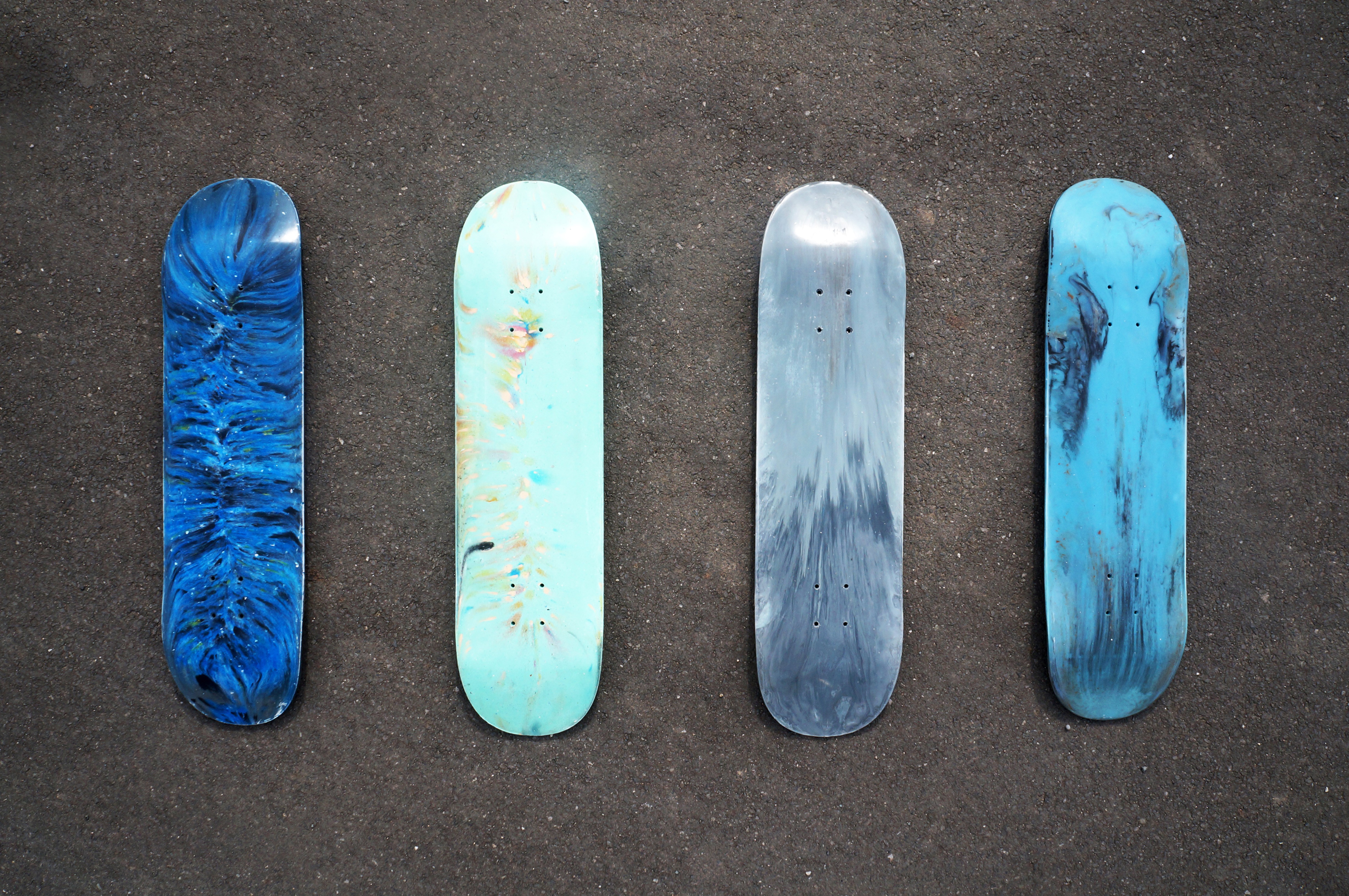
The easiest way to make a gradient in a deck is to sprinkle a bit of plastic near the entry hole, then when you extrude over the top it will spread it along the entire mould.
2.2.3
Lower the top face, using the chain hoist, re-install the top support structure and the bolts.
Wide shot lowering
*Angle 8
2.2.4
Arrow Shot
Notice it has arrows on the top, these show direction of the flow of the plastic so you know which way round it should go.
When tightening the bolts start with the middle two, then one end, then the other end.
Close up mould top
*Angle 2
2.2.4
Use the impact driver and offset handle to tighten them, in the same way you loosened them.
2.2.4
To ensure the mould is tightly closed, use the socket wrench and the offset handle with the extension, applying as much force as you can by hand to fully tighten the bolts.
Close Up
2.2
PPE
Before turning on the mould or the extruder make sure to turn on your ventilation. We used some oven hoods, directly above the mould
*Angle 1 Close Up, Ventilation
2.2.5
Now plug in the control boxes of the mould and the extruder.
Close ups
*Angle 1
2.2.5
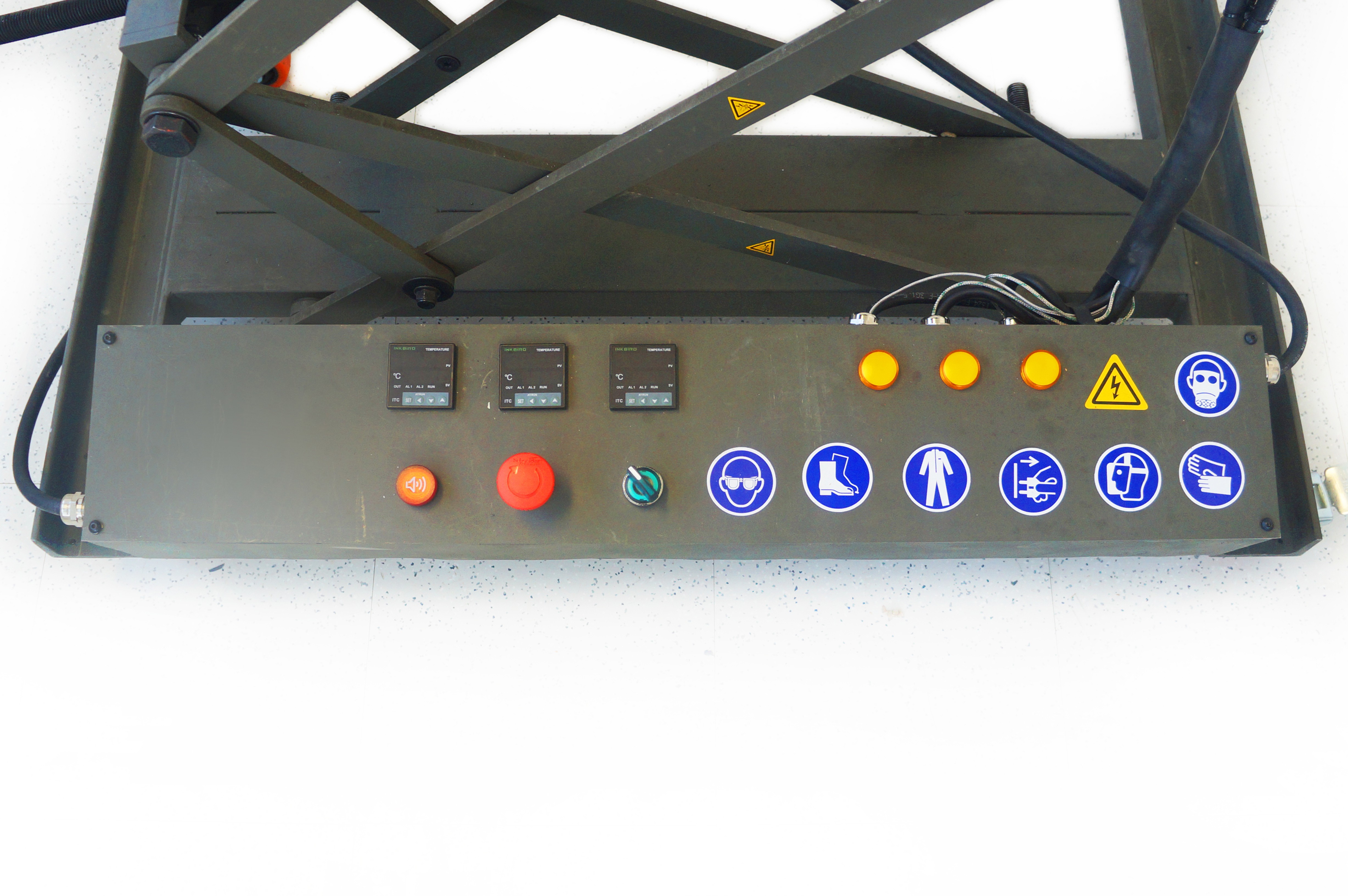
Switch them on, using the green switch, making sure the emergency stop is released.
Close ups
*Angle 3
*Angle 4
2.2.5
Set the PID controllers to the required temperature. For this video we are going to use Polypropylene, so the temperatures and speeds shown are to work with this material, but if you change plastic type you may need to change them.
Close ups
*Angle 3
*Angle 4
2.2.5
On the extruder, set the first PID controller slightly less than the second two
All three next to each other.
*Angle 3
*Angle 4
2.2.5
Now wait for the mould and extruder to heat up. It should take around 15 mins for the extruder and 30 mins for the mould.
Clock sped up
2.2.5
While they heat up you can prepare your plastic. You can and about 20% of a pure color to white or transparent and still get a very strong tone.
If you want to test the material to see its color or how it melts, now is the best time.
Melting out of nozzle, Gradient
*Angle 1
2.2.6
Place a bucket of cold water under the hopper.
Extrude in to bucket
*Angle 1
2.2.6
Wait until five minutes after all the PID controllers have reached their temperature.
5 mins Clock sped up
*Angle 4 PIDS 260
2.2.6
Add your plastic to the hopper
Extrusion
*Angle 1
2.2.6
Set the potentiometer on the motor control panel (Arrow on screen) to the lowest setting
Close Up VFD
*Angle 4
2.2.6
Then press the green button on the motor control panel to start the extrusion screw.
2.2.6
Slowly turn up the potentiometer on the motor control panel until it reaches around 15.
2.2.6
To make sure the plastic doesn't get stuck in the hopper stir the granules using a beam, ideally made from the same material that you are extruding as sometimes bits get broken off the end by the screw and sucked into the barrel. Alternatively you can use wood, but not metal.
Semi Wide
*Angle 1
*Angle 7
2.2.6
Under any circumstance do not put your fingers into the screw otherwise they can get broken too!
Sticker
2.2.6
Watch as the plastic comes out the end of the nozzle to see if it is melting correctly and that you are happy with the color. Let the plastic collect in the bucket. You can re shred it and use it later.
Melting out of nozzle, Gradient
2.2.6
Finally press the red button on the motor control panel to stop the extrusion screw
Close Up VFD
*Angle 4
2.2.6
Whilst the mould is preheating you can prepare to attach the nozzle to the extruder.
Two Nozzles
Close up
Close up
*Angle 5
2.2.7
You’ll notice we added a tap to the mould, this is to quickly lock in the plastic when the mould is full without losing any pressure and without any plastic leaking out.
Tap Shot
*Angle 5
2.2.7
We found that a ½ inch tap is the best. ¾ inch is too hard to release and ¼ inch breaks too easily.
3 Taps X tick X
2.2.7
We put a tap on the exit hole also, as this one doesn't take much pressure it can be smaller, ¼ inch is enough. It should be left open when filling the mould.
Close Up
2.2.7
The tap must be opened to fill the mould.
Gently try and open it, don't force it, it can break,
If its stuck it most probably has plastic inside
You can use a heat gun to soften it and try again
Once it sopne you can use a drill bit to clean it, use the m4 drill to make a pilot hole and the m10 to clean out the bulk. Be careful not to drill the threads, or the aluminum block and make sure the tap is open.
Thumbs up shot
2.2.7
If there is any leftover plastic debris in the thread fr, you can use a heat gun and a flat head screwdriver or spatula to clean it.
2.2.7
Check your PIDS to see if they have reached temperature, if not, wait a bit.
PID Reaching Going Up Slowly
*Angle 4
*Angle 3
2.2.7
Once the PID controller on the mould has reached temperature, wait 5 minutes and give the bolts on the mould one last tighten using the socket wrench and offset handle, before attaching it to the extruder. They can become loose in the heating process.
*Angle 2
*Angle 3
Clock sped uo
2.2.8
Line up the nozzle of the extruder with the nozzle of the mould
Using the handles, attach the mould nozzle to the end of the extruder.
Attaching nozzle
*Angle 5
2.2.8
If necessary, move the adjustment bolt, with the socket wrench, to align the mould nozzle to the end of the extruder.
*Angle 1 Wide shot height adjust, close shot them aligning
2.2.8
When it's fully tight, lock the wheels of the extruder with all 4 breaks.
Close up
2.2.8
Filling the mould
To fill the mould start by adding your plastic to the hopper
Top down pouting in to hopper
2.3
On the motor control panel, set the potentiometer (Arrow on screen) to the lowest setting
Close Up VFD
*Angle 4
2.3
Then press the green button to start the extrusion screw.
2.3
Slowly turn up the potentiometer on the motor control panel until it reaches between 5 and 10.
Let it run slowly for the first five mins to clear out any plastic from the entry to the mould without building up too much pressure.
2.3
After five mins you can turn the potentiometer up to around 30.
2.3
Continue to add plastic to the hopper. Don't let the hopper empty at any point otherwise air will get pumped into the mould and you will get air bubbles in the deck.
Hopper run dry X on screen
*Angle 7
2.3
Remember to stir the plastic
Every few mins check to see if plastic is coming out of the exit hole.
Wides shot, close up exit hole
*Angle 6
2.3
Once you see the plastic coming out of the exit hole, close the exit tap
Closing tap
*Angle 6
2.3
Continue to extrude into the mould for ~3 mins after plastic starts to exit the mould, to build up pressure inside it.
Wide shot extruding
2.3
Finally press the red button on the motor control panel to stop the extrusion screw and immediately close the entry tap to lock the pressure inside.
Close up VFD
*Angle 4 VFD (40-0)
*Angle 5 Nozzles
2.3
Unlock the breaks on the extruder.
Close up
2.3
Using the quick release handles, unscrew the mould from the nozzle of the extruder.
Close up separation
*Angle 5 Nozzles
2.3
Immediately put a threaded end cap in each end of the mould whilst it is still hot to keep any overflowing plastic out of the thread.
End Cap
*Angle 5 Nozzles
2.3
Once the cap is in place you can also open the tap again to make it easier to clean after.
*Angle 5 Nozzles
2.3
Now that they are separate you can turn off both the extruder and the mould using the green switch on the control box.
Switch off green button
*Angle 4
*Angle 3 (Use reverse of into at 40)
2.3
Move the extruder away, position your cooling fan in place, and turn it on.
Wide shots
*Angle 1 Whole Set
2.3
With active cooling, like this, it takes around one hour for the mould to cool down. If you leave it to cool without a cooling system it takes 3-4 hours, so we highly recommend getting one.
Close Up Clock,
Cooling system
2.3
Opening the mould
You can check that mould is cool by turning it on briefly to see the temperature on the PID, or by using a thermometer. If it is less than 60 degrees it's ready to open.
Phone camera
*Angle 3 Control Box
2.4
Once it is cool you can start opening the mould using the same technique that you used to open it at the beginning of this video, with the impact driver on the bottom, which catches the nut, and the driver offset handle on the top.
Semi-Wide Opening
*Angle 2
2.4.1
Again, so that you don’t lose them; you can keep them in the pocket in the top support structure.
2.4.1
If the impact driver is not strong enough you can loosen them with the socket wrench and offset handle.
2.4.1
Again, if the bolts are really stuck. You can use an extension handle to get a bit more leverage.
2.4.1
Once all the bolts are removed, lift off the top support structure and place it to one side.
Wide Shot (
*Angle 1
2.4.1
Run the lifting strap through the middle two handles on the top face and hook them on the chain hoist. Lift the top face to see if it lifts off without any more work. Be careful not to lift the whole mould too high if it doesn't open immediately as it may separate in mid air and fall onto your feet (its 380kg). If this is all it takes to open it, great!
Hoist Mould
*Angle 8
Close up of mould top
2.4.1
If not, don't worry, there are a few things you can do to help get it open.
Talking in to camera
*Angle 8
2.4.2
You will notice a small slot around the edge of the mould between the C beams and the horizontal plate.
Closeup
2.4.2
- Take the crowbars, and try to lever the mould open in the same spots, between the handles. If you have a friend around, ask them to help you. Sometimes this is all it takes so you can try again to lift it open. Once it has opened a bit you can easily slide the cold chisels in to prevent it from closing again.
Sem-Wide
*Angle 8
2.4.2
If this doesn't work
*Angle 8
2.4.2
- Take 4 small chisels and hammer them into the spaces between the handles to release the mould a little bit. Then Repeat with the 4 big ones.
Semi-Wide
*Angle 8
2.4.2
When trying either of these techniques do not lever from the ends as this puts a lot of stress on the end bolts connecting the aluminum deck face to the steel horizontal plate, and may tear the threads.
Show doing wrong
2.4.2
- Finally there is a 3rd method you can try, there are 4 m20 threaded holes in the horizontal plate, These are release holes. Take 4 m20 hex bolts and tighten them by hand in the holes. Now take the socket wrench and turn each of them a ¼ turn, at a time, in rotation, to slowly lift up the top face. This method should only be the last resort as it puts a lot of wear on the mould.
Close up of M20 Holes/
Quarter Turn
*Angle 2
2.4.2
Once you have freed the top face fully and lifted it fully, release the breaks and move the mould out from underneath it, revealing your deck.
Hero Shot
*Angle 2
2.4.3
You can lever the deck out of the mould with a flat tool, we found these which are designed for removing car upholstery. Use something soft, like plastic.
Lever
*Angle 2
2.4.3
Never use anything metal otherwise you will scratch the mould.
Screwdriver chisel X
2.4.3
You can also try using suction cups.
Semi-Wide
*Angle 2
The deck should easily lift out, as the plastic shrinks a little bit as it cools.
Cutting little plastic bit
*Angle 2
2.4.3
Place the deck to one side on something soft
Wide, putting deck down
*Angle 2 (Placing shot)
2.4.3
Clean any flash plastic off of the mould with a hammer, chisel and spatulas. Make sure the top face is clean.
Scraping
*Angle 2
2.4.4
Apply a layer of silicone oil to the top and bottom face of the mould.
*Angle 2
2.4.4
Position the mould back under the top face and lower it using the chain hoist to keep the top face of the deck protected.
Lowering Wide
*Angle 8
2.4.4
If you are going to make another deck right after, remember to put the next batch of colored plastic by the entry hole for creating the gradient.
*Angle 8
2.4.4
You can also place the top support frame on top of the mould and re-insert the nuts and bolts in the mould so that they don't get misplaced. This also keep the inside of the mould clean.
Speed up semi wide
*Angle 8
2.4.4
3. Finnish the deck Now the deck has been shaped there are a few last things you need to do to finish it.
Talking in to camera, Workbench
*Angle 9
3.1
Grip
The first thing is to clean and grip the deck.
Talking in to camera, Workbench
*Angle 9
3.2
You are going to need:
Top Shot
3.2
· A hand drill
· A 5.5mm drill bit
· A small countersink
· A de burring tool for sheet metal
· A fine half round file
· Hand Sanatizer
· Clean rag · Spray mount
· Grip Tape
· Alan key
· Wrench
· Ruler
· 8 M5x40mm countersunk bolts (Two a different color)
· 8 M5 Locknuts
· Some raiser pads
Top Shot
3.2
Start by drilling the truck holes.
*Angle 9
3.2
You’ll see eight pilot holes, take the hand drill and the 5,5mm drill bit and drill them from top the bottom face of the deck to the top face.
*Angle 9
3.2
Now take the countersink and countersunk the holes on the top face of the deck so that the hardware sits below the surface.
*Angle 9
3.2
Next, using the metal deburring tool, give the edge of the deck a radius.
Close Up
3.2
To make sure that grip tape sticks well, we are going to apply a layer of spray mount to the deck.
*Angle 9
3.2
Stick the grip tape to the top of the deck, starting in the middle and working out towards the nose and the tail.
*Angle 9
3.2
Use a half round file to remove the excess grip, by running it at 45 degrees along the edge of the deck.
*Angle 9
3.2
Be careful in the dip at the beginning of the transition to the nose and the tail, a lot of the time the grip doesn't stick well here, sometimes it needs an extra spray of glue.
*Angle 9
3.2
You can also use a razor blade to remove the excess grip, but it really helps if you mark it first with the file.
Close Up
3.2
Trucks
Finally we are going to install the trucks
*Angle 9
3.4
You need longer bolts than normal decks, we use 40mm.
Close Up Bolts
3.4
We suggest using soft riser pads to protect the plastic from the sharp metal edge of the trucks. We found these, Niks Originals, made from cork, a link is in the description to this video.
Holding up to camera
*Angle 9
3.4
Install the trucks, the deck has a nose and a tail, the nose is longer and higher than the tail, you can check by using a ruler.
You can also tell by the arrows on the mould. The arrow points to the nose of the tail, or the direction you would skate it.
Close Up of Calipers
3.4
You can differentiate the two by putting two different colored bolts at the tail of the deck.
2 bolts different colors
3.4
Tighten the nuts, and your deck is done!
Talking in to camera, Workbench
*Angle 9
3.4
Now it's time to hit the street!
Holding up finished deck
*Angle 9
3.4
4. Trick Montage 5. Outro RPSD is a non profit organization publishing open source plastic recycling research online for free.
If you would like to support the development of this project follow the URLS below to like us on Facebook, follow us on Instagram, join our mailing list, make a donation and become a supporter on Patreon.
Sharing our posts and spreading the word about our project opens a lot of doors for us! We are also very keen to hear about any collaborations or opportunities you guys see! https://linktr.ee/projectRPSD
Thanks for watching!
See you next timeWhite Wall
Mould, skateboards and extruder out in front of me
*Angle 1
5
Angle 1: Full Studio Shot
Angle 2: White Frame Shot Perspective
Angle 3: Control Boxes
Angle 4: VFD
Angle 5: Nozzle
Angle 6: Exit Hole Close Up
Angle 7: Hopper Downward Shot
Angle 8: White Frame Shot Square
Angle 9: Workbench Shot
-
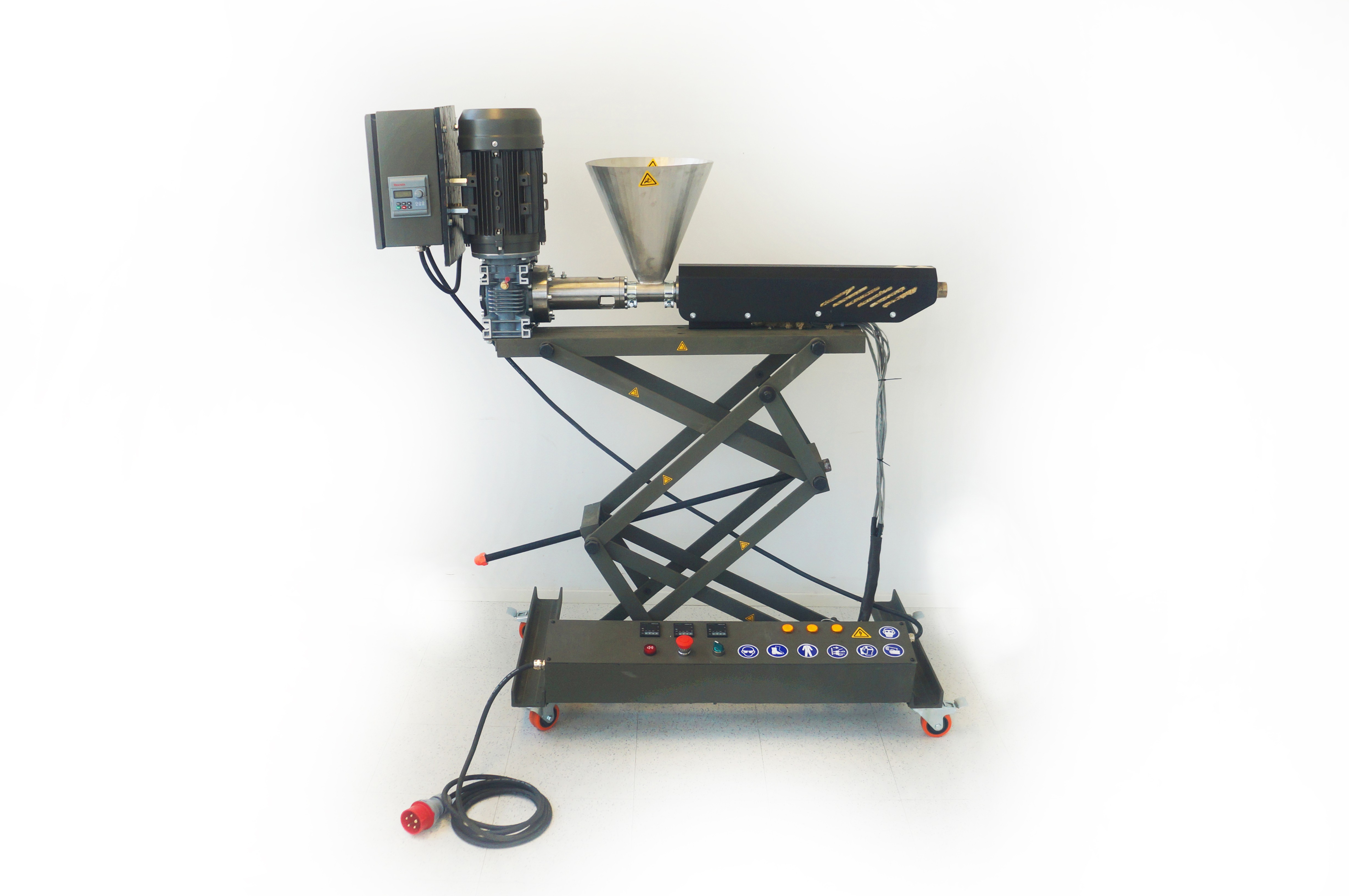
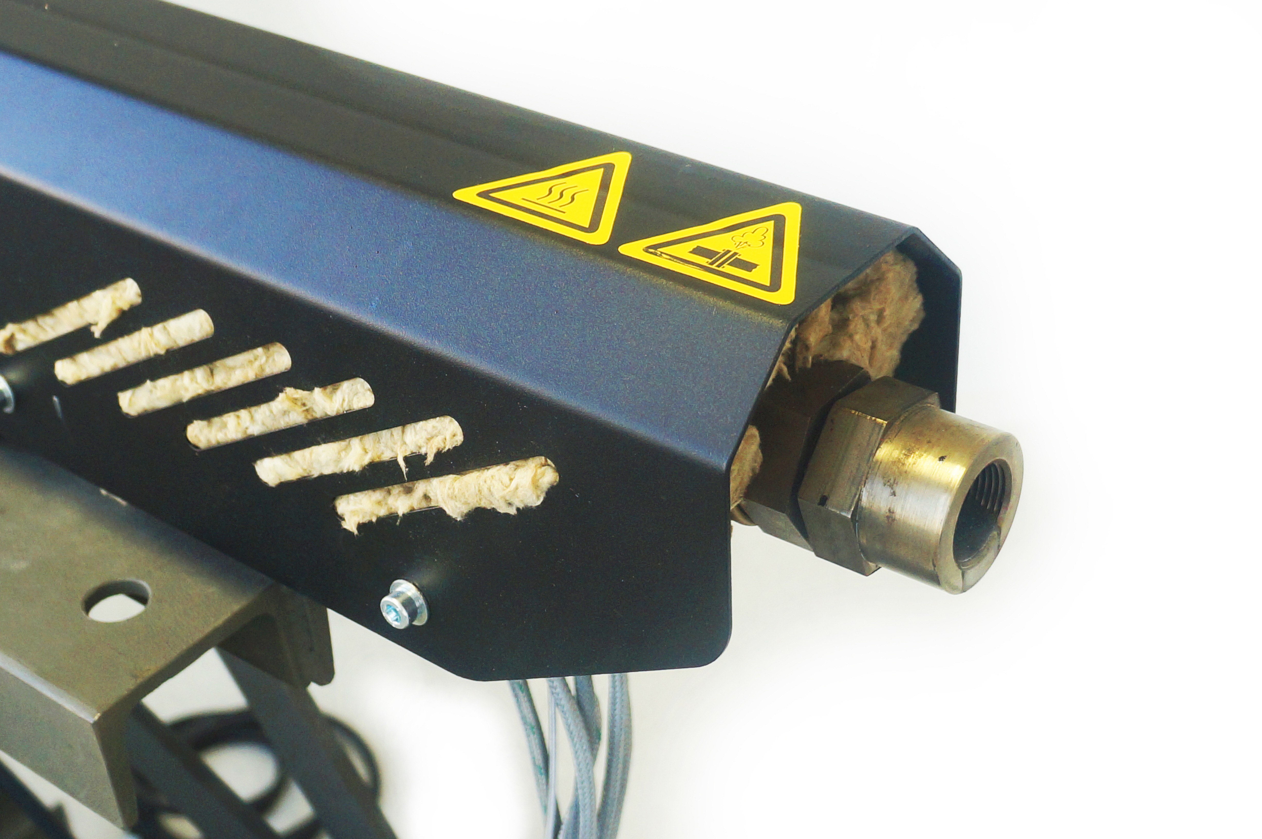
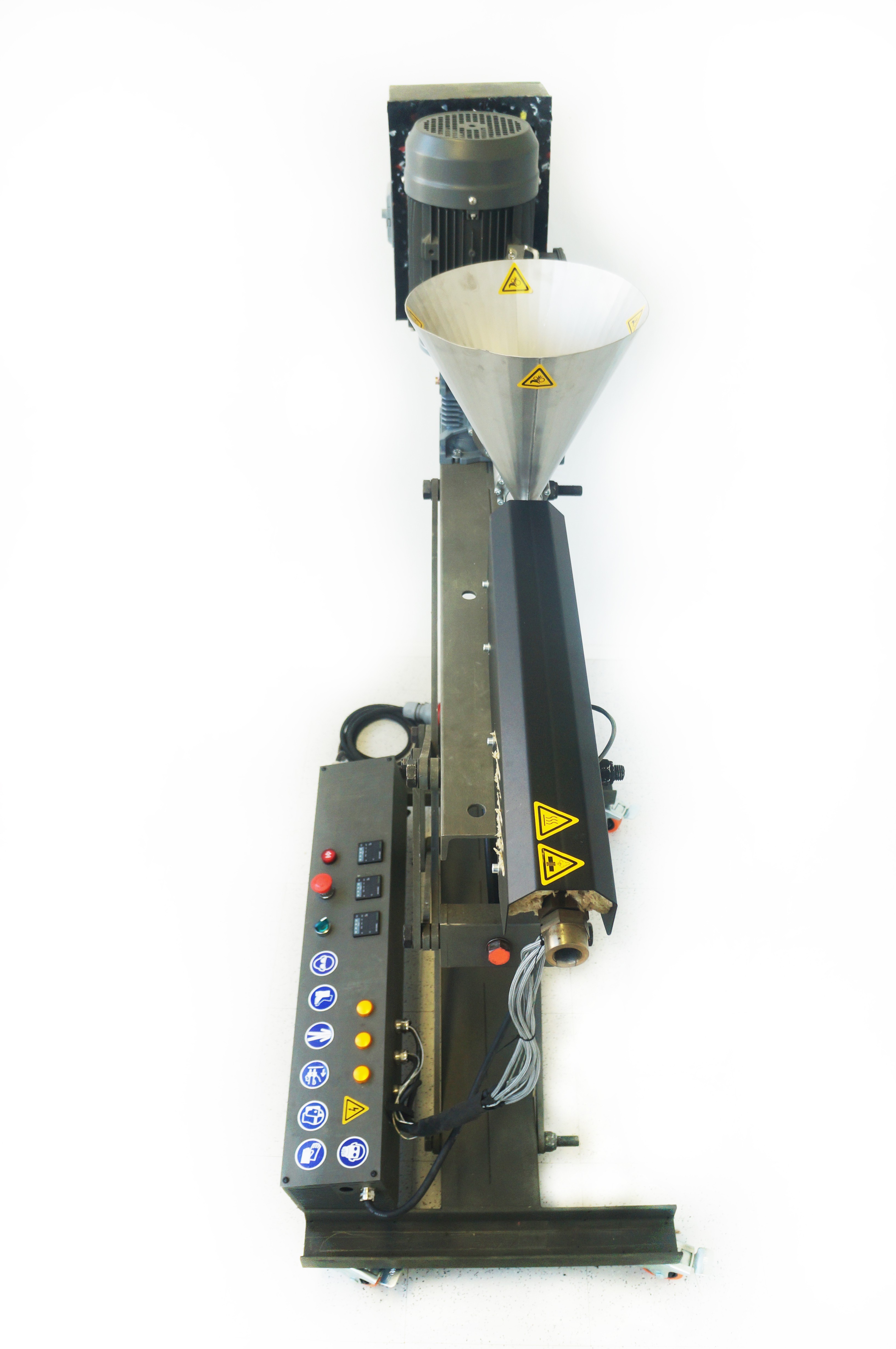
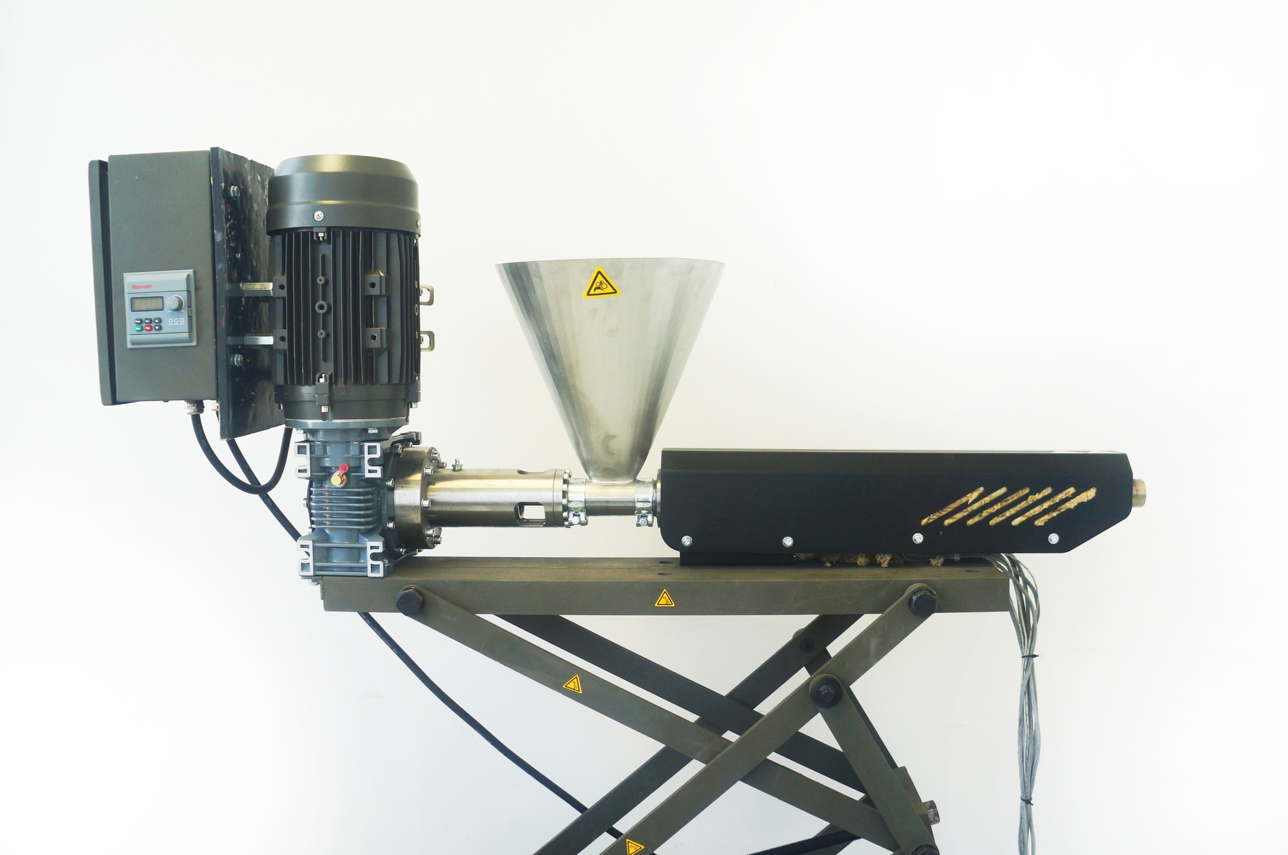
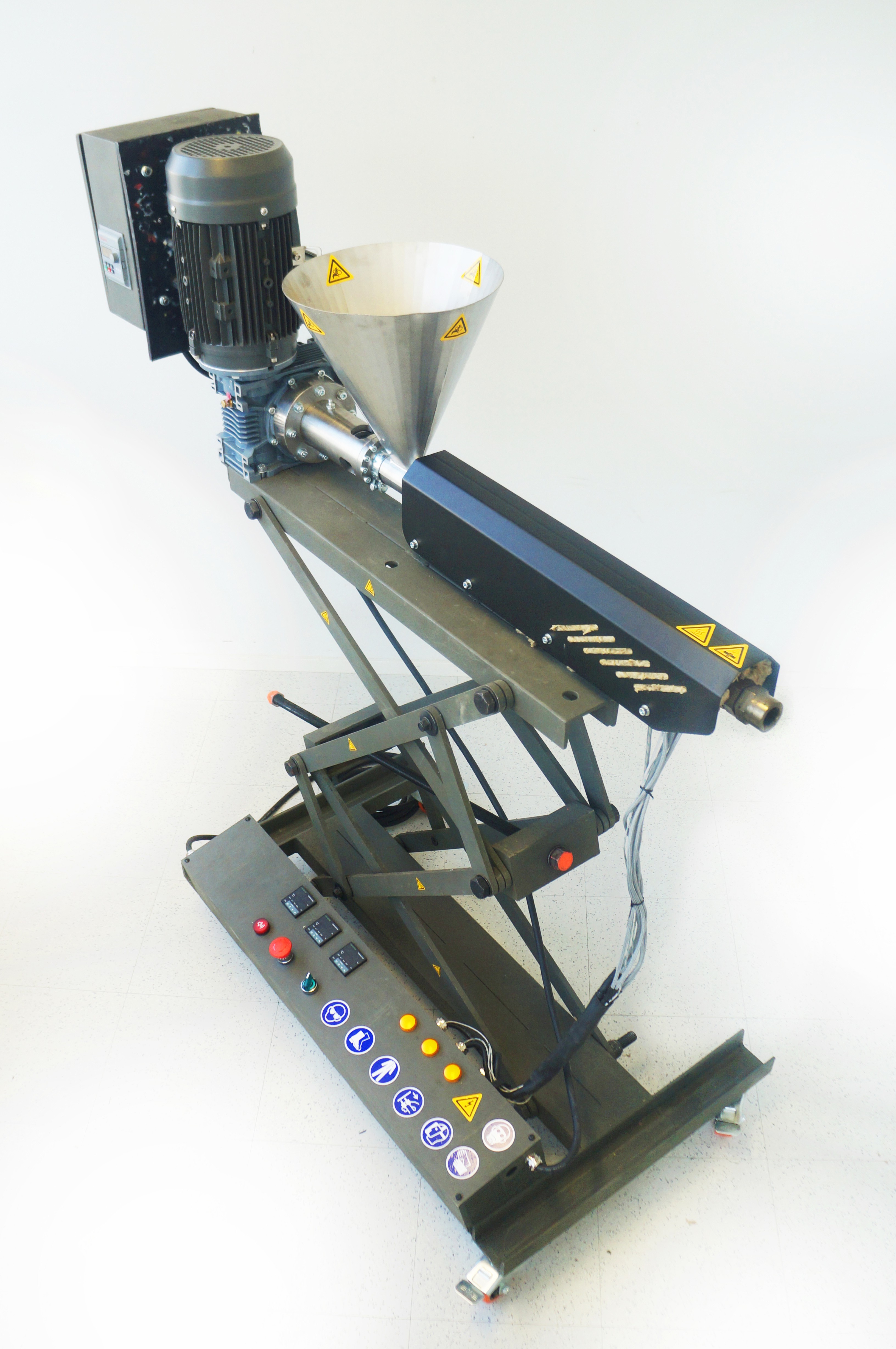
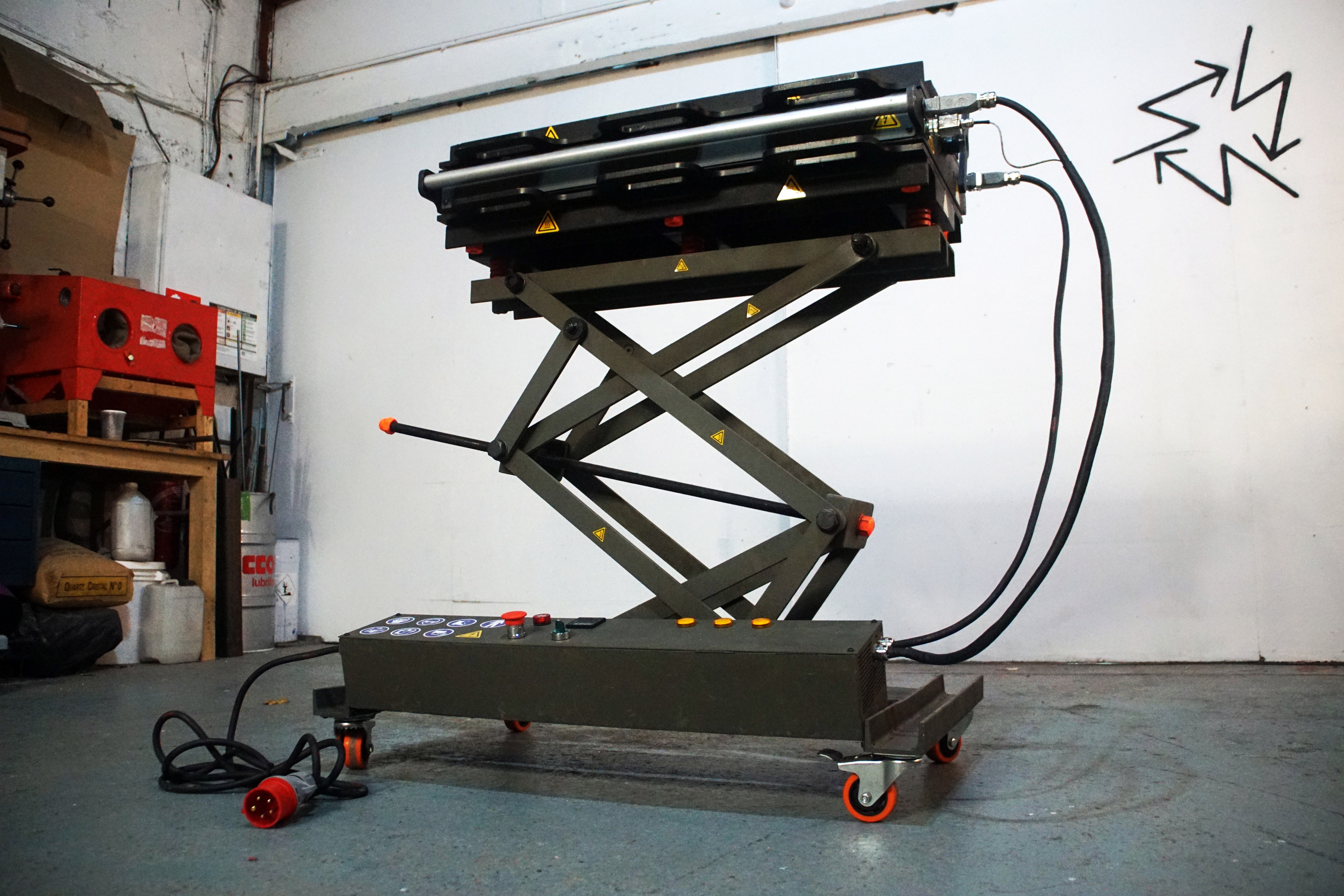
RPSD Extruder
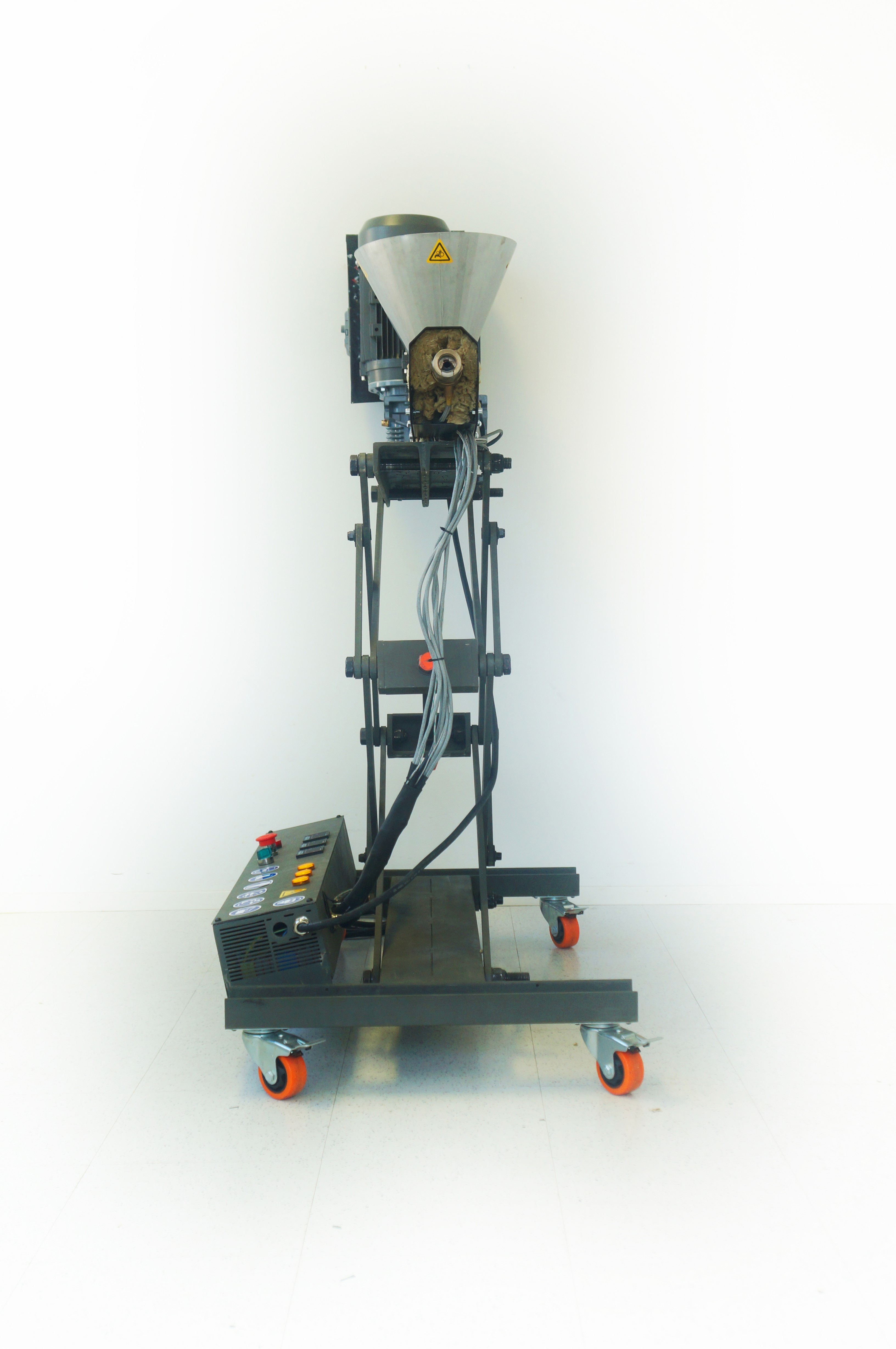
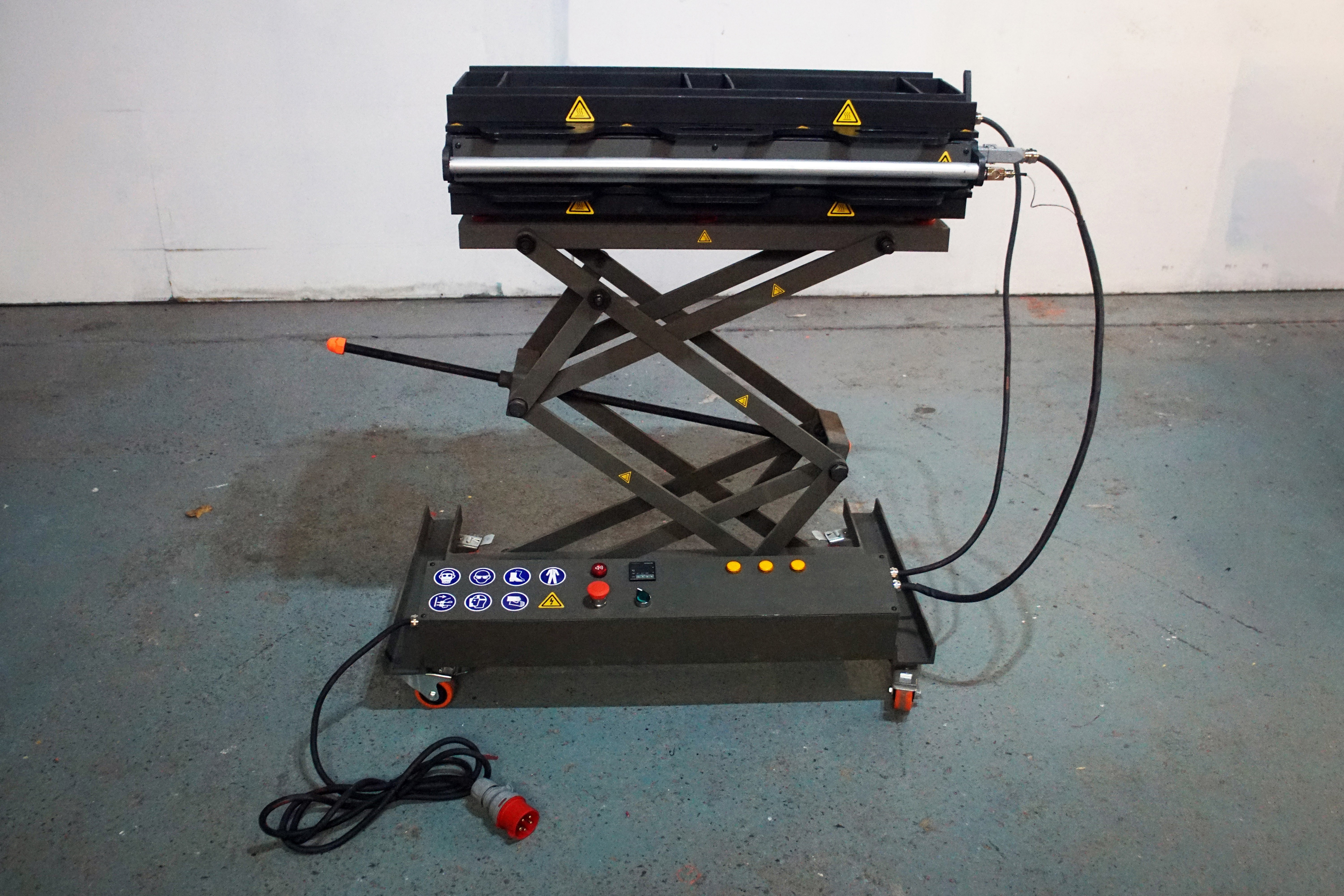
08/24/2022 at 20:29 • 0 commentsTo make recycled plastic skateboard decks, you need an extrusion machine. It melts the plastic into a liquid and fills the mould by pushing the molten plastic out of a barrel using a motorized screw.
![]()
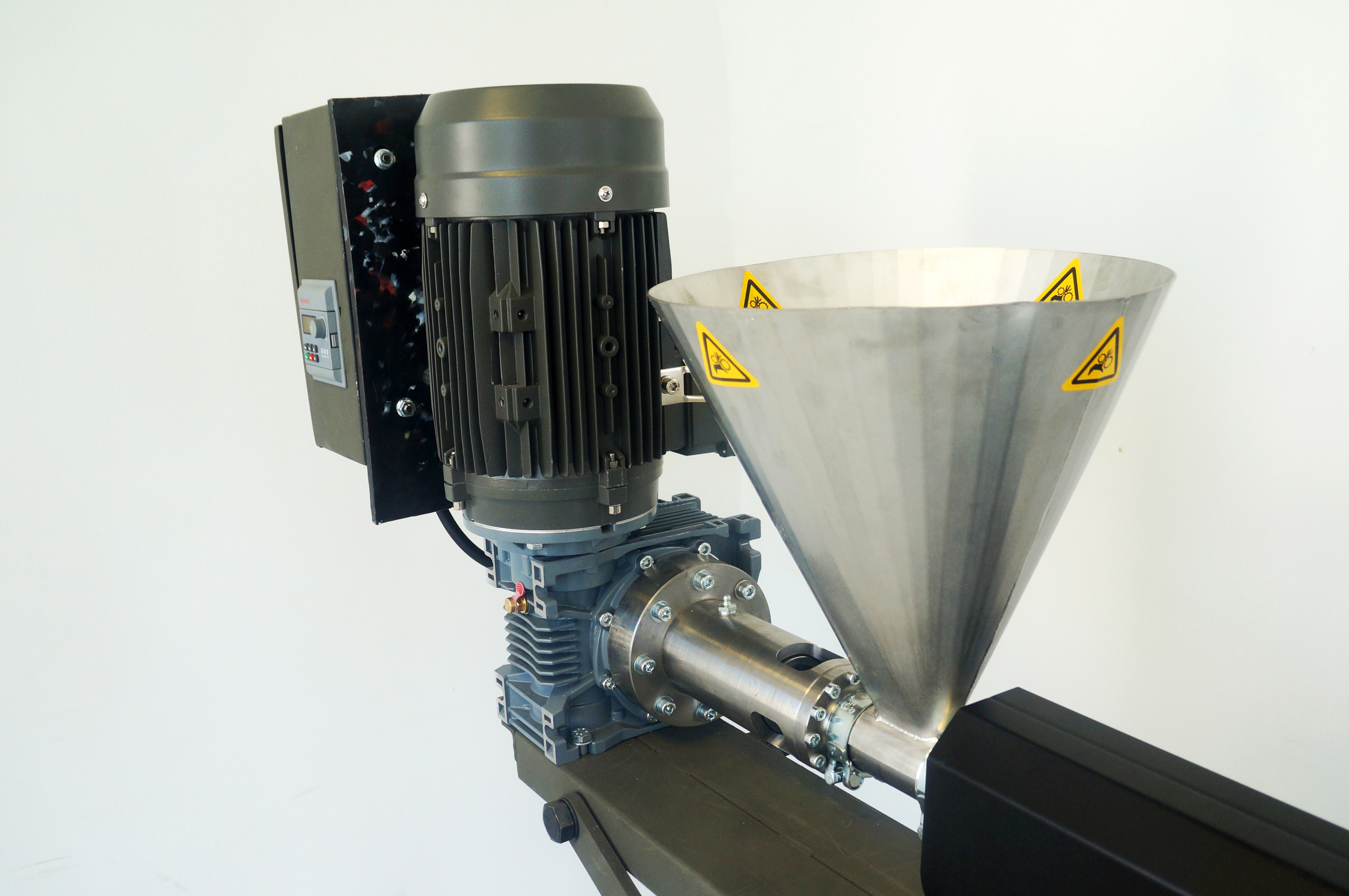
There are many variations of the extrusion machine out there but none were perfect for our needs, so we set out to design one that fits, as a set, with out mould, to complete the production system. What differentiates ours is that it has an adjustable height, wheels, and lean profile (700mm wide) making it practical for events, demonstrations or simply moving around the workshop. The adjustable height allows it to be used for a broader range of applications that require a low or high profile, or for interactions that involve children and shorter people.![]()
Like all our work, this machine is fully open source and online now, you can find the download kit 📦 HERE 📦
This kit includes all the information you need to build your own extruder.![]()
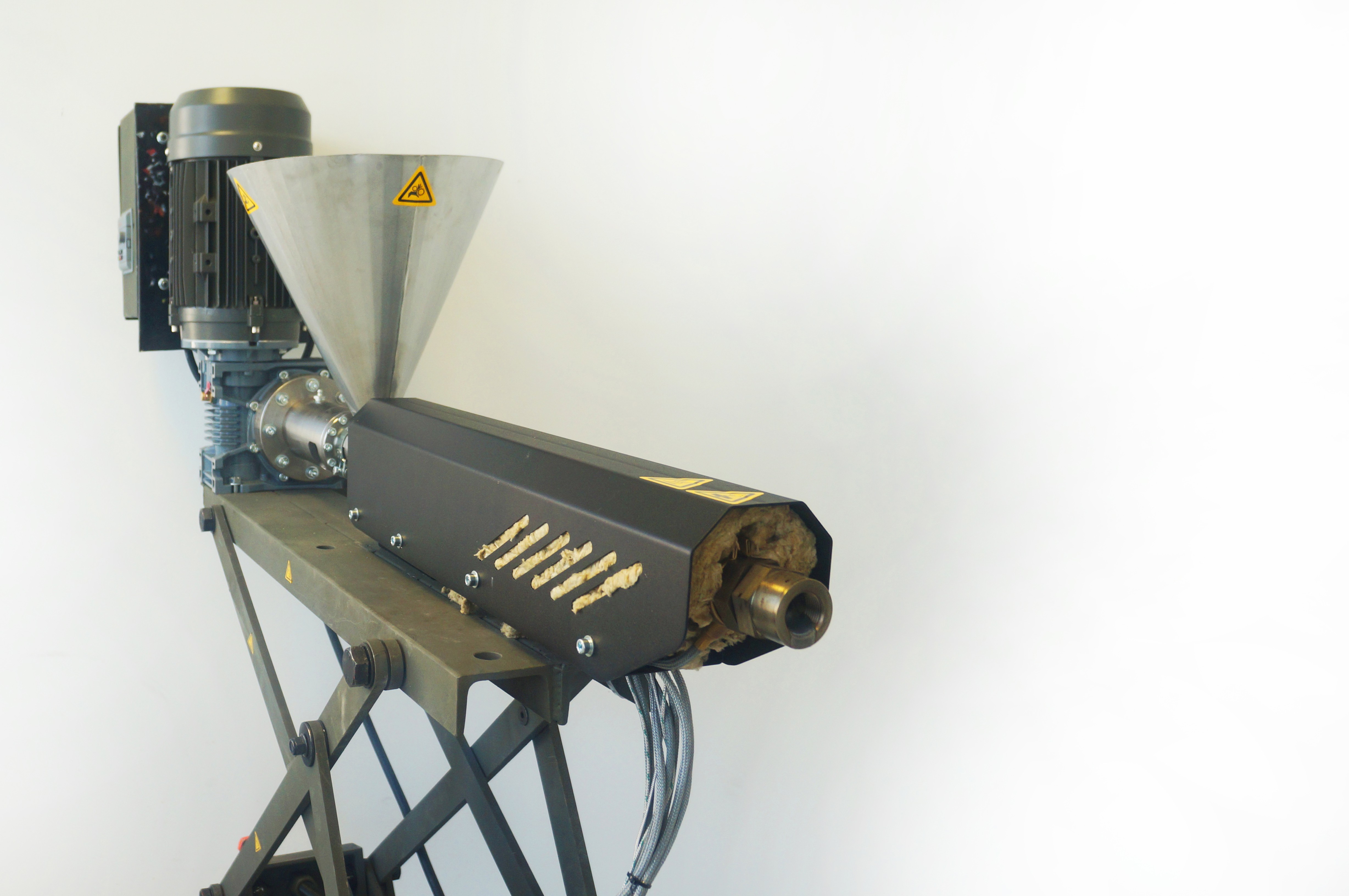
The extruder features an extrusion barrel designed by Ateliers des recycleurs fous. It is from their model “C4-PO”. More information, such as how to build it, can be found here:atelierdesrecycleursfous.fr/extrudeuse
Special kitos (Thanks) to Caracara Collective for the many kinds of support given during this phase of the build.
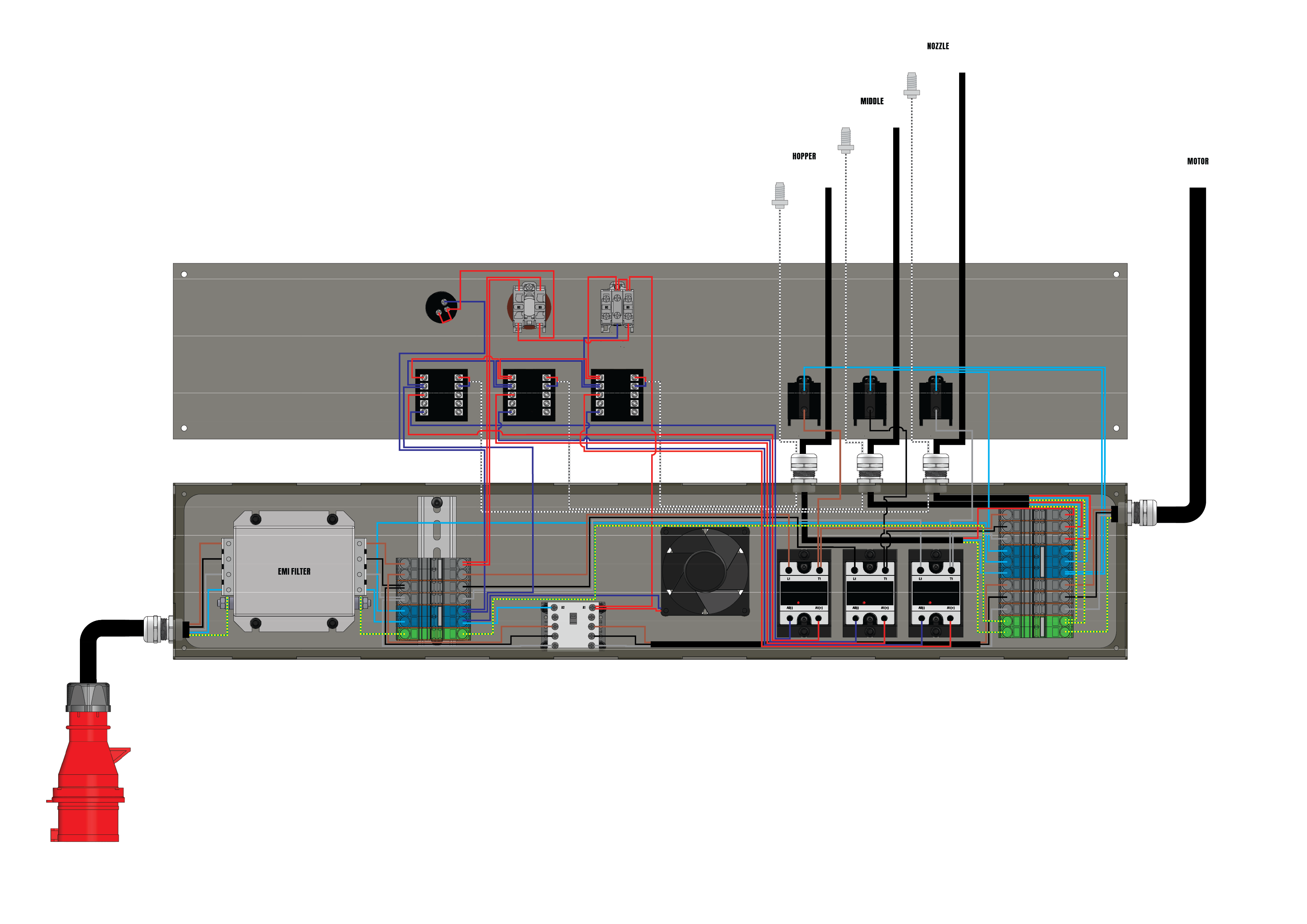
Electronics Schematic
![]()
RPSD-EXT Technical Data
General
Model
RPSD-EXT
Version
1.0
Type
Extrusion
Year
2022
Dimensions (length x width x height)
1400 x 700 x 500 min 1400 max
Mass
200 kg
Total Power
5 kw
Total Amps
12 A
Heating
Power supply
Three-phase electric - 380V
Heating element type
Band Heater / Collar
Number of heating elements
6
Heating power
2 kW
Operating temperature
0 to 250 °C
Motor
KW
3.3 kw
Amps
137 Nm
RPM
187
User Process
Materials processed
Soft plastic, Hard plastic
Filling Method
Extrusion
Construction
Construction materials
Steel Frame
Material Cost (EU)
7500 Euro
Manufacturing time
± 5 Days
Workforce
1 Person
Difficulty
★ ★ ★ ☆ ☆
Connections
Electrical
Three phase plug socket 16 A
Pneumatic
Compressed air for cleaning
![]()
![]()
![]()
![]()
![]()
![]()
![]()
-
Mould Technical Data
05/29/2022 at 14:07 • 0 commentsMould Technical Data
General
Model: RPSDMV3
Version: 3.0
Type: Extrusion
Year: 2021
Dimensions (l x w x h): 1100 x 700 x 500 min 1300 max
Mass: 285 kg
Heating
Power supply: Three-phase electric - 380V
Heating element type: Cartridge Heater
Number of heating elements: 64
Heating power: 10600 W
Operating temperature: 0 to 250 °C
User Process
Materials processed: Soft plastic, Hard plastic
Filling Method: Extrusion
Construction
Construction materials: Steel Frame, Aluminum Body
Material Cost (EU): 7500 Euro
Manufacturing time : ± 5 Days
Workforce: 1 Person
Difficulty ★ ★ ★ ☆ ☆
Connections
Electrical: Three phase plug socket 16 A
Pneumatic: Compressed air for cleaning
-
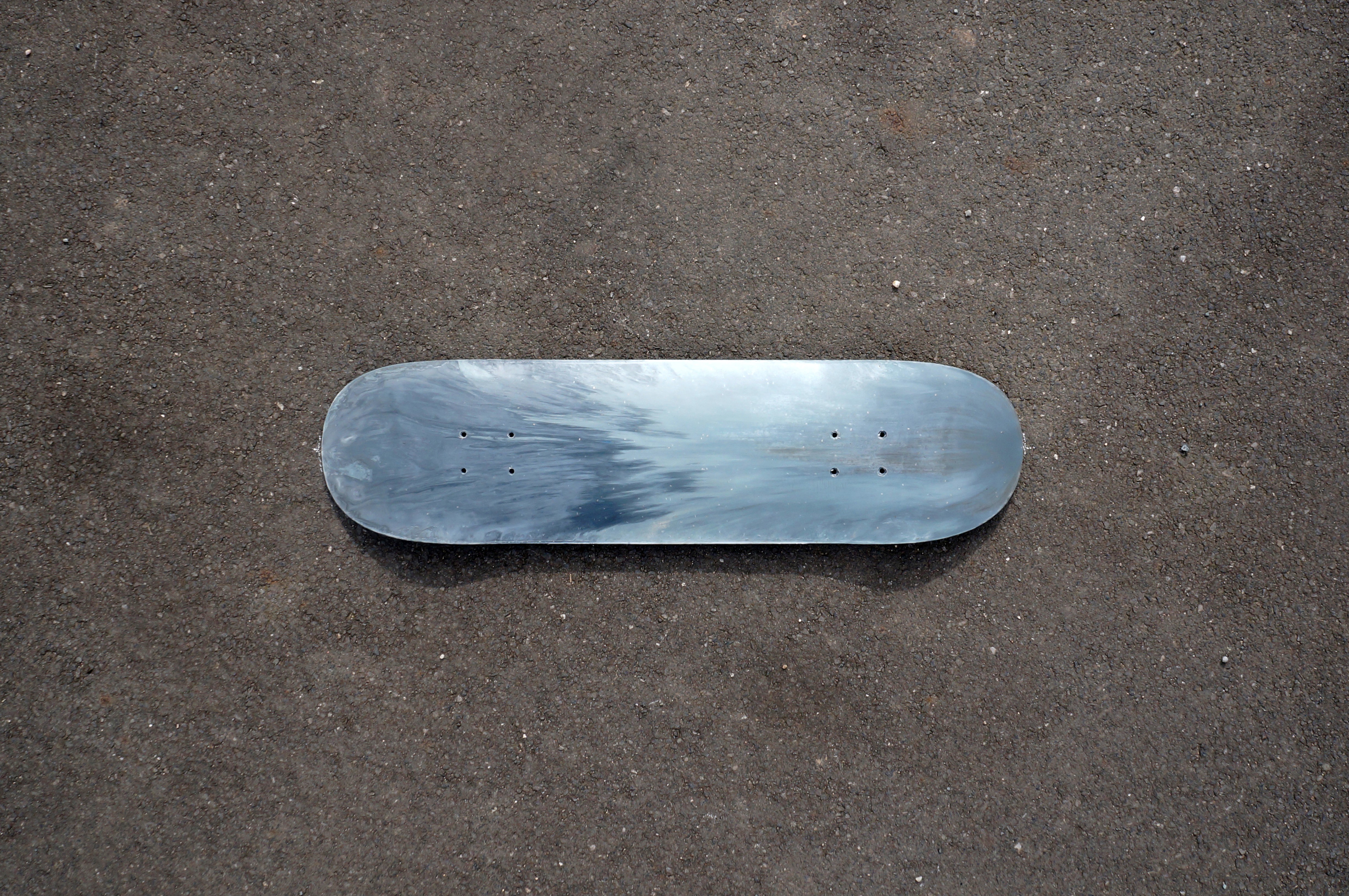
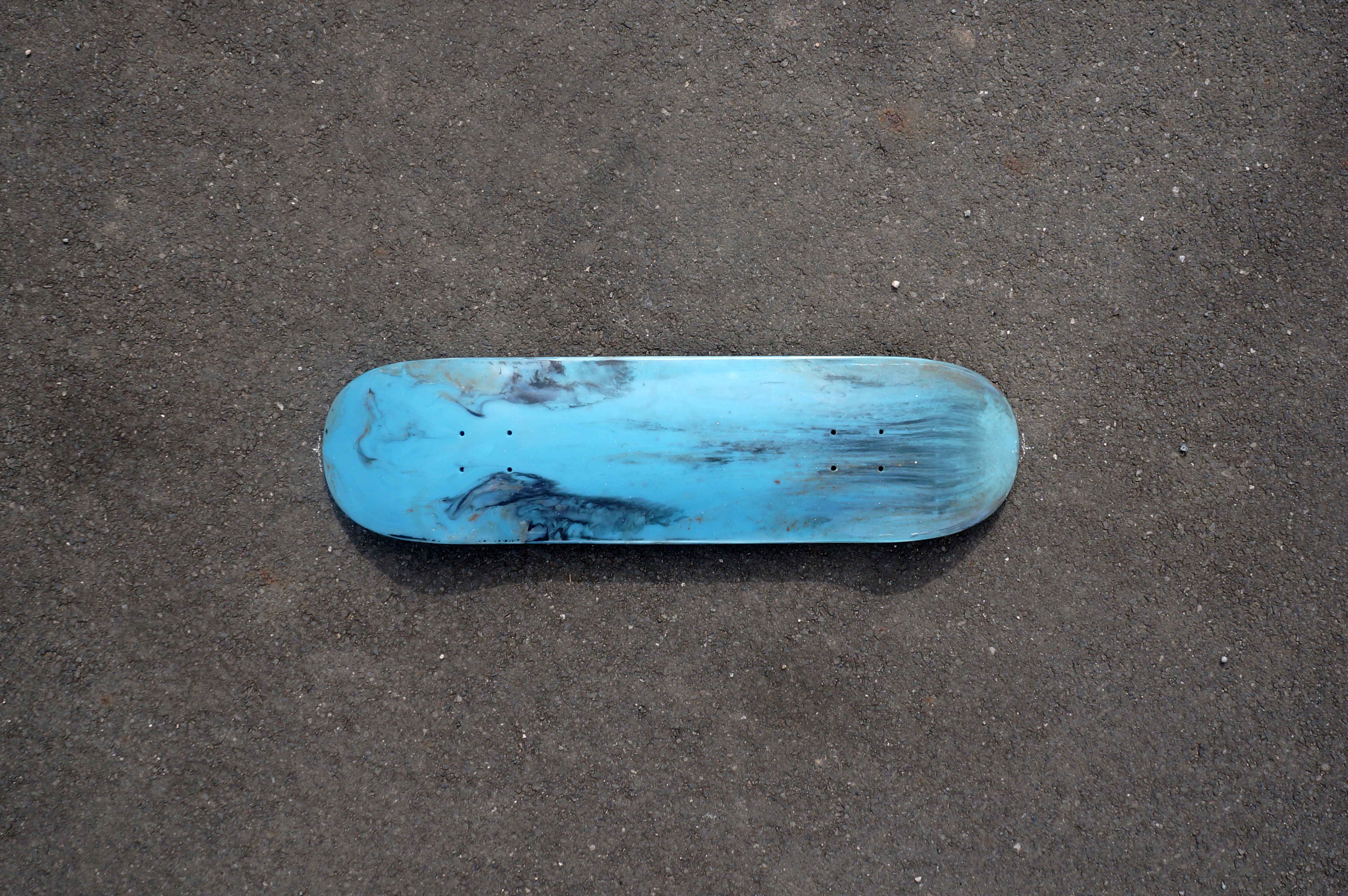
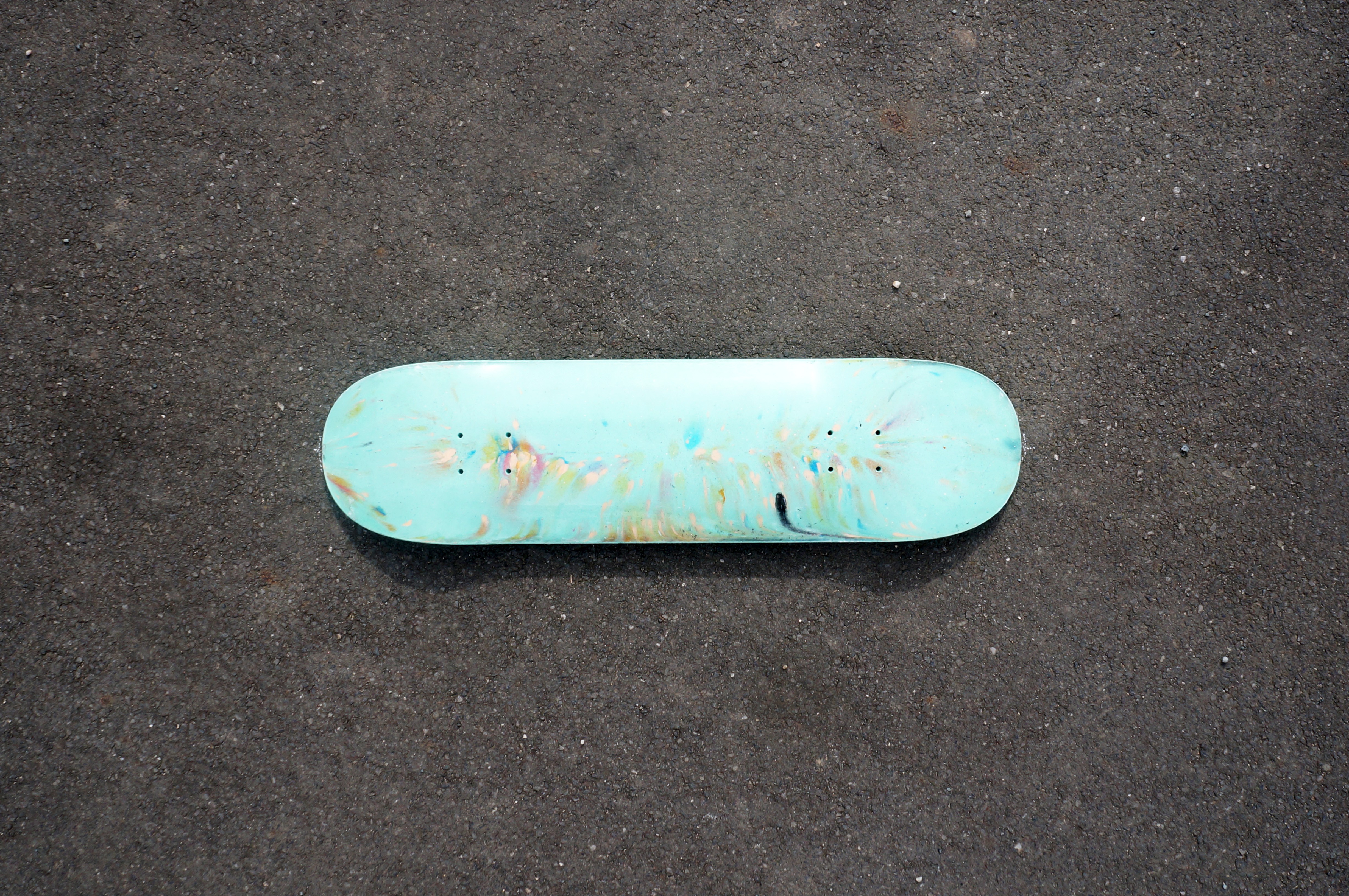
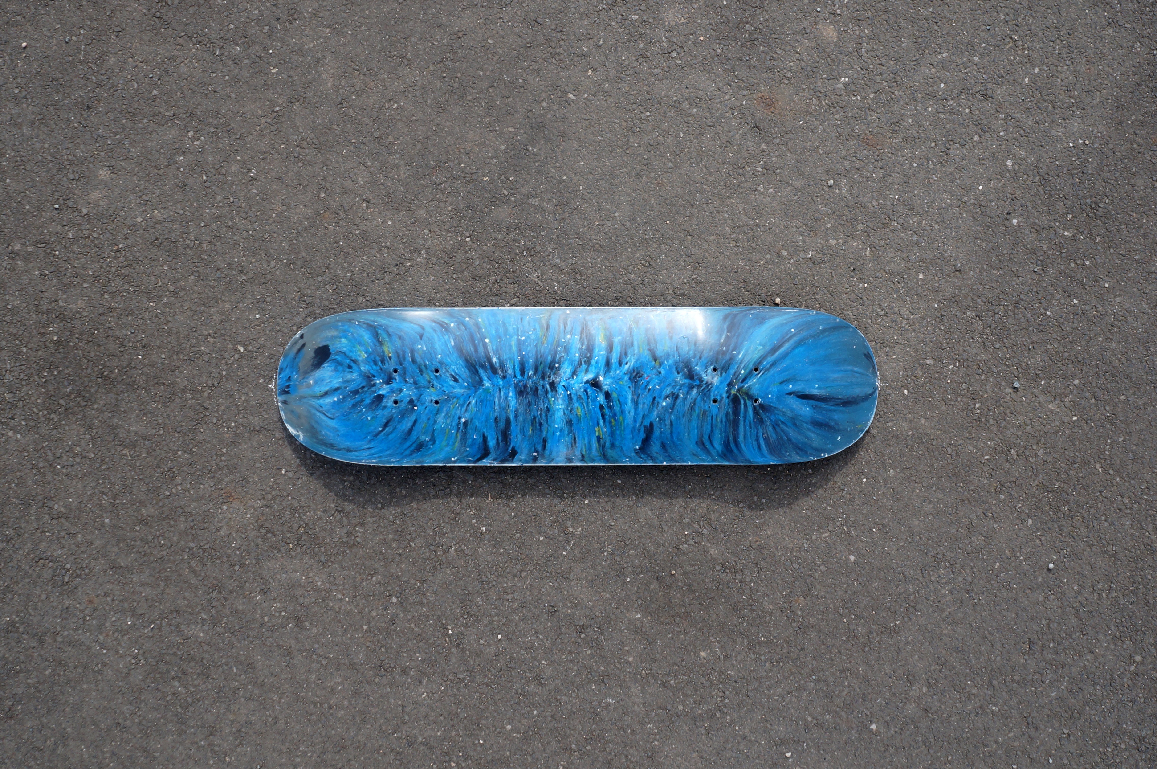
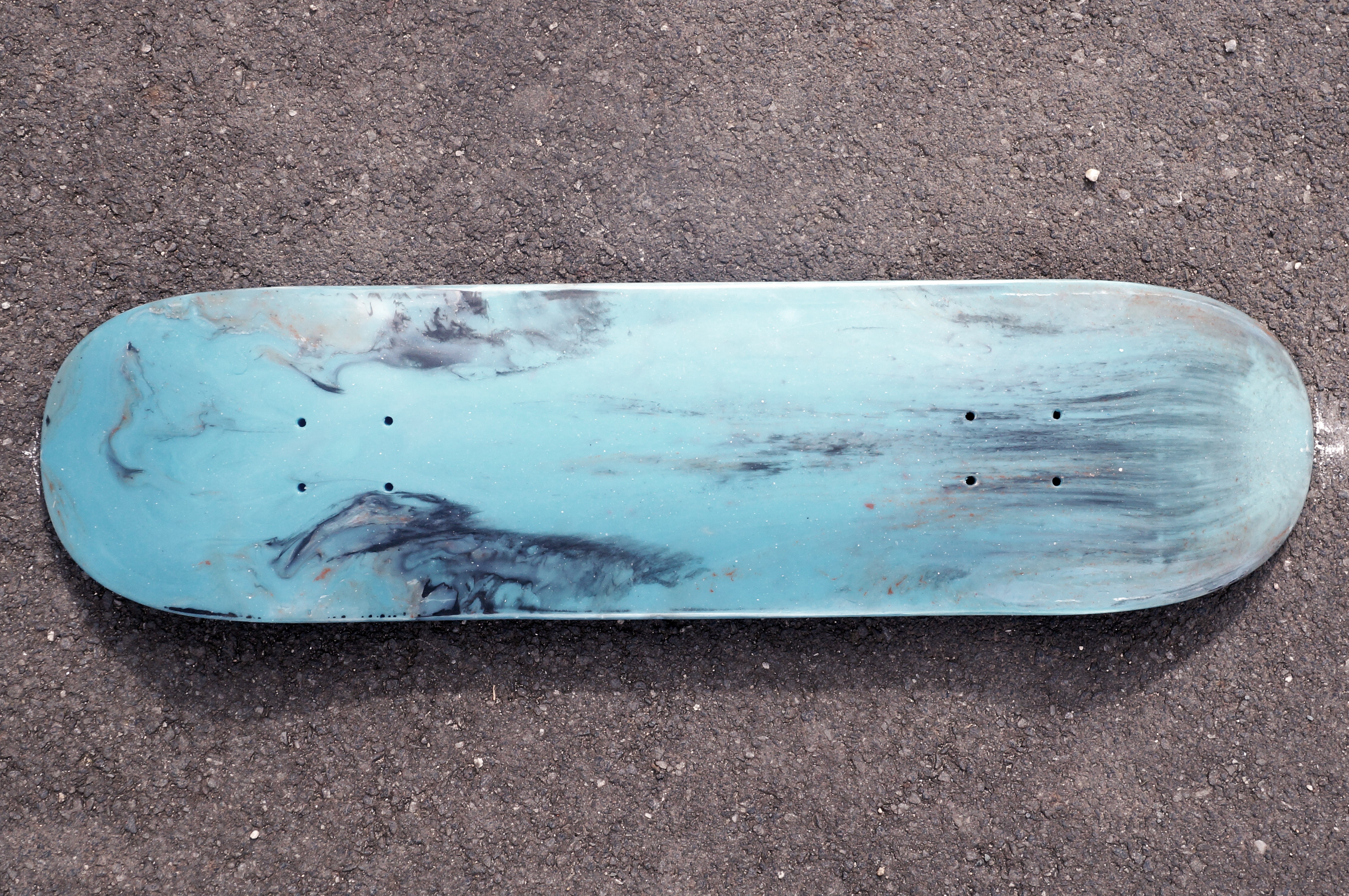
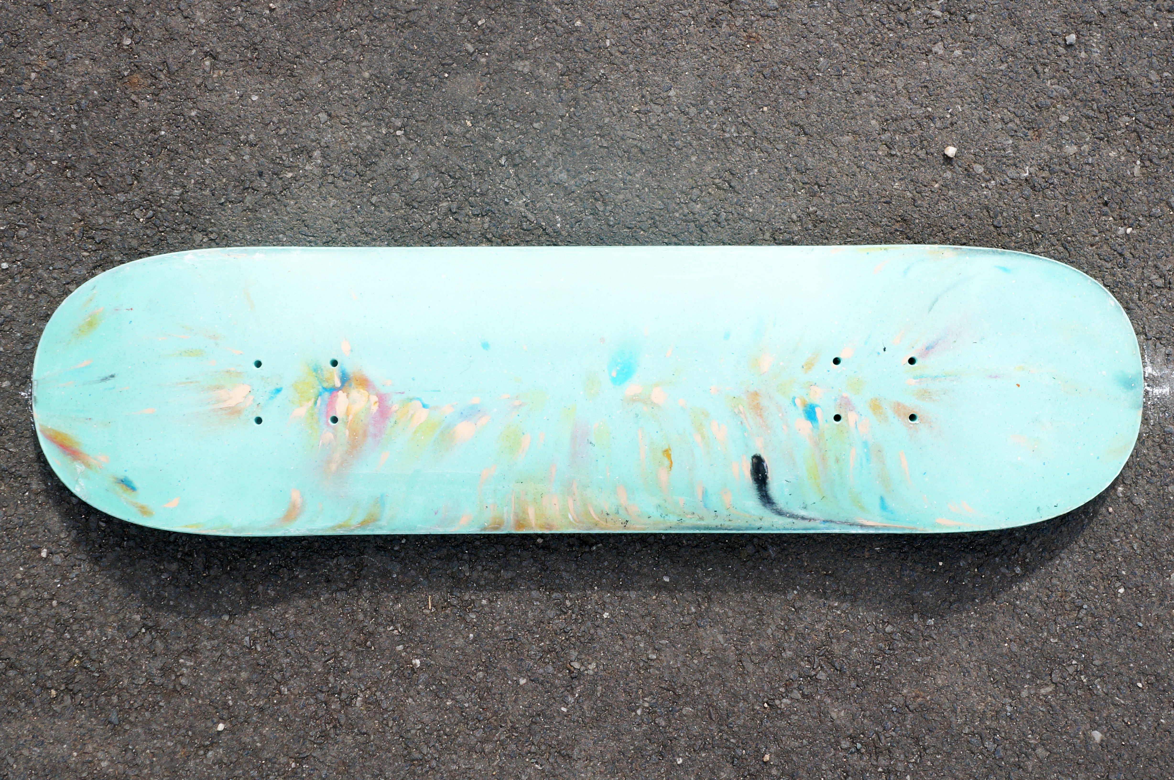
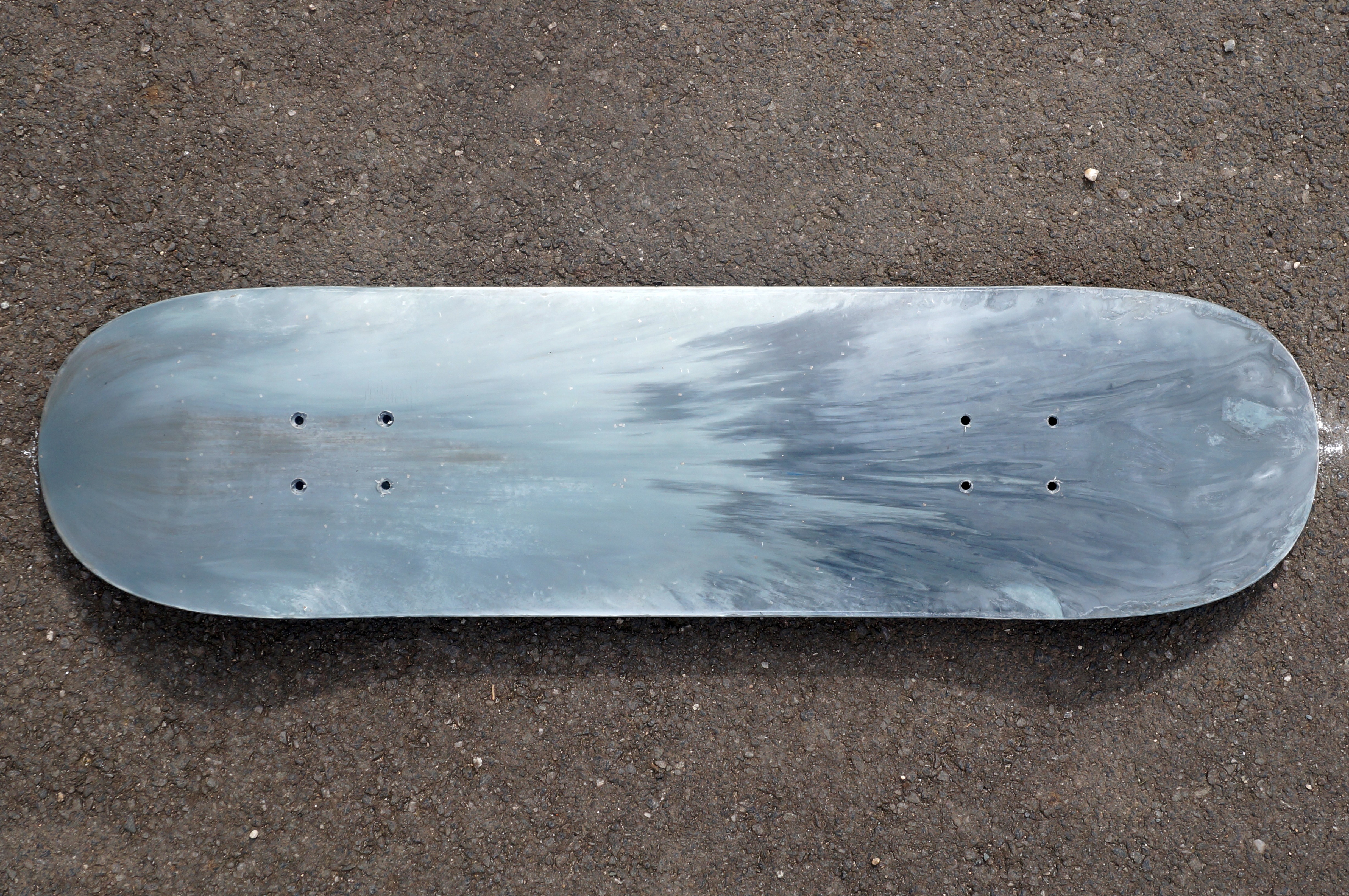
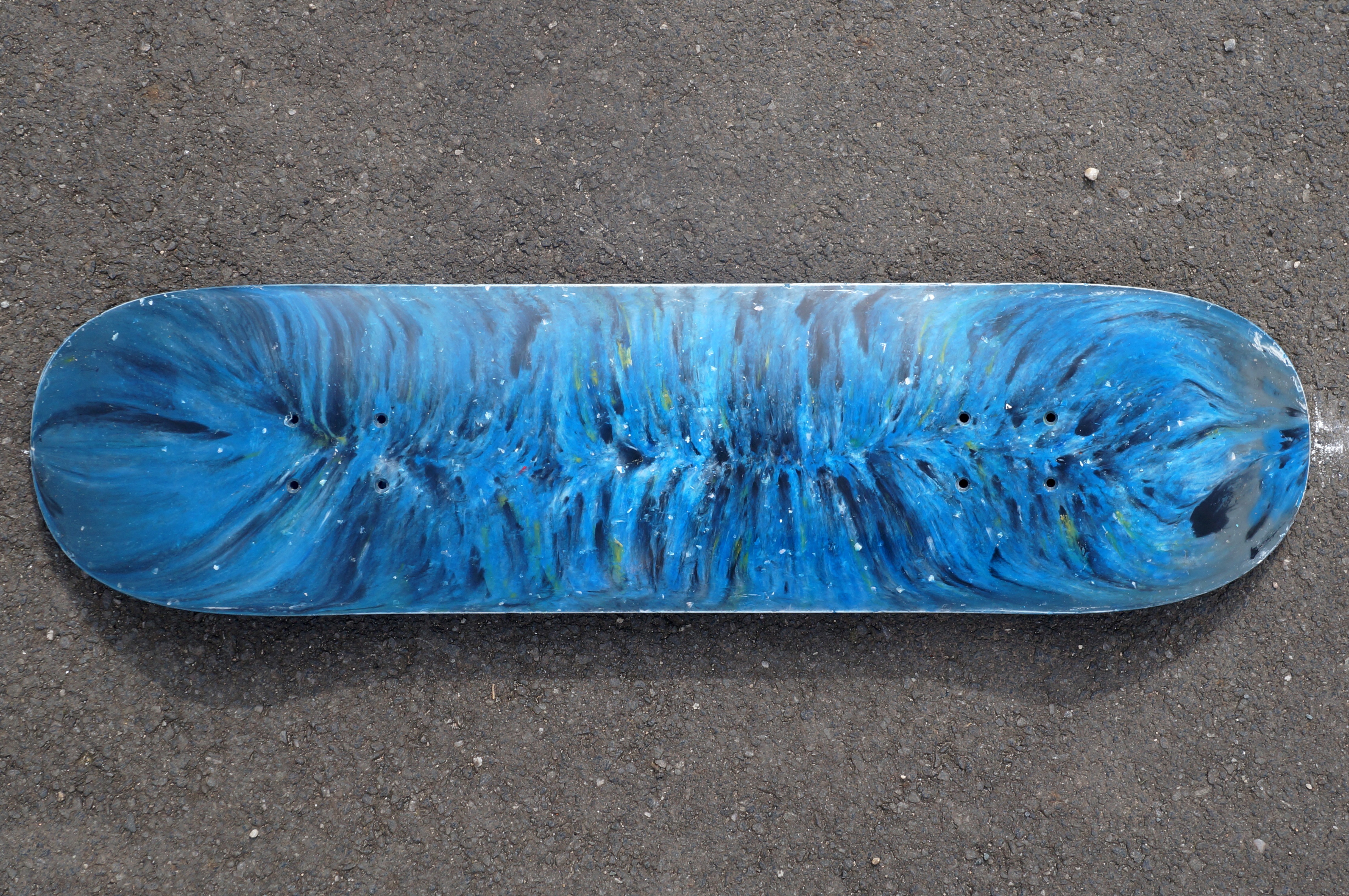
Deck Pattern Variations 1
05/29/2022 at 14:01 • 0 comments![]()
![]()
![]()
![]()
![]()
![]()
![]()
![]()
![]()
![]()
![]()
![]()
![]()
-
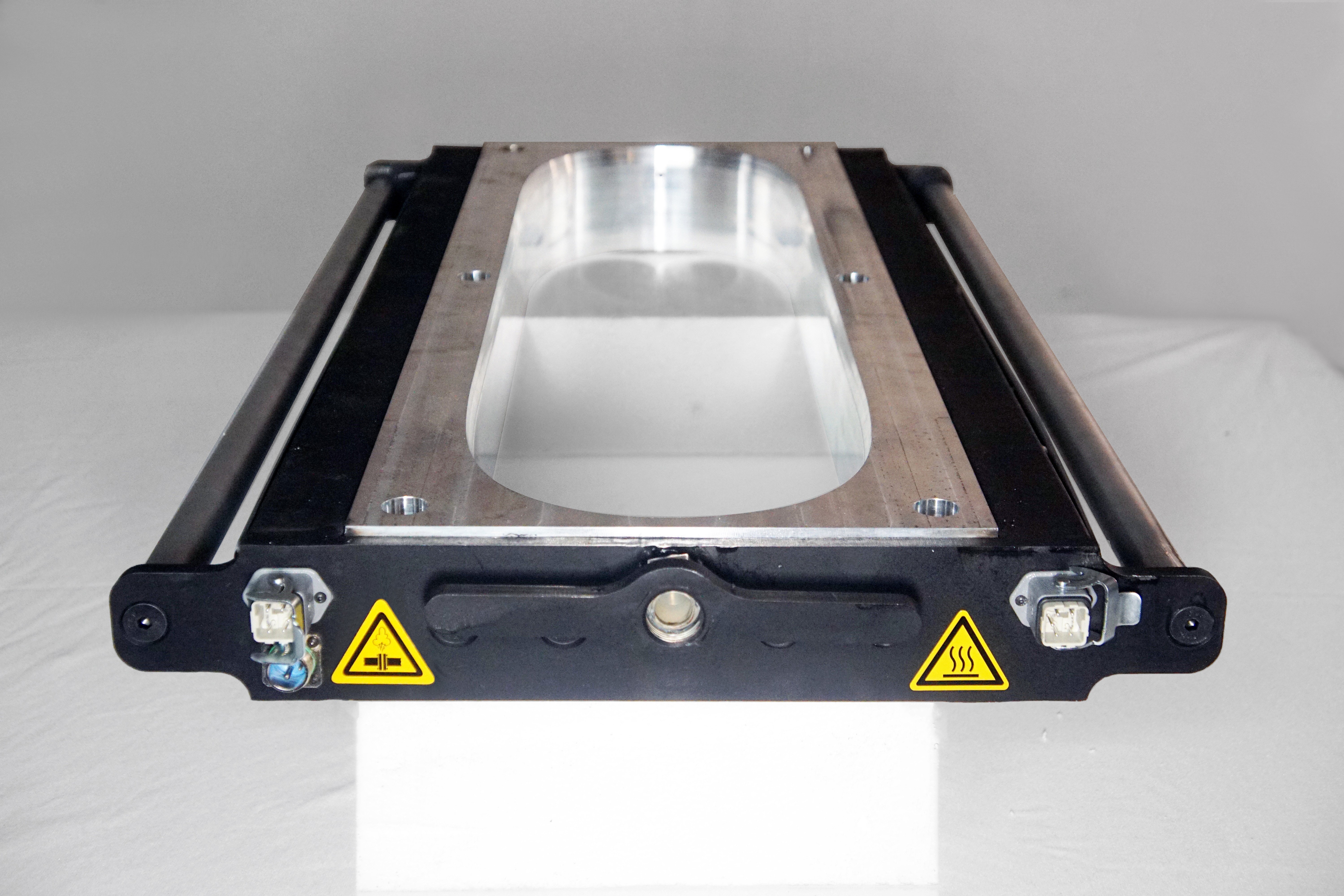
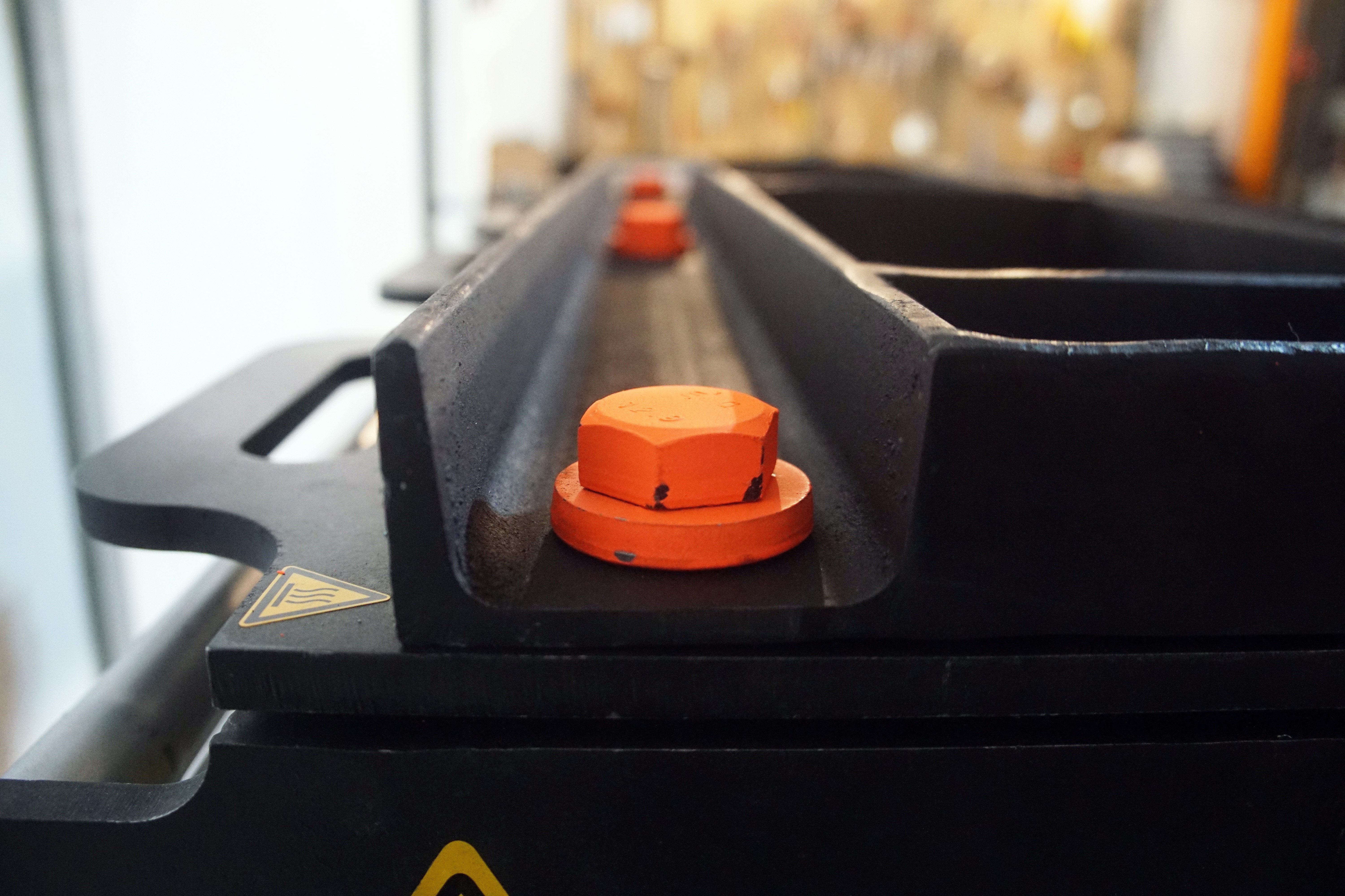
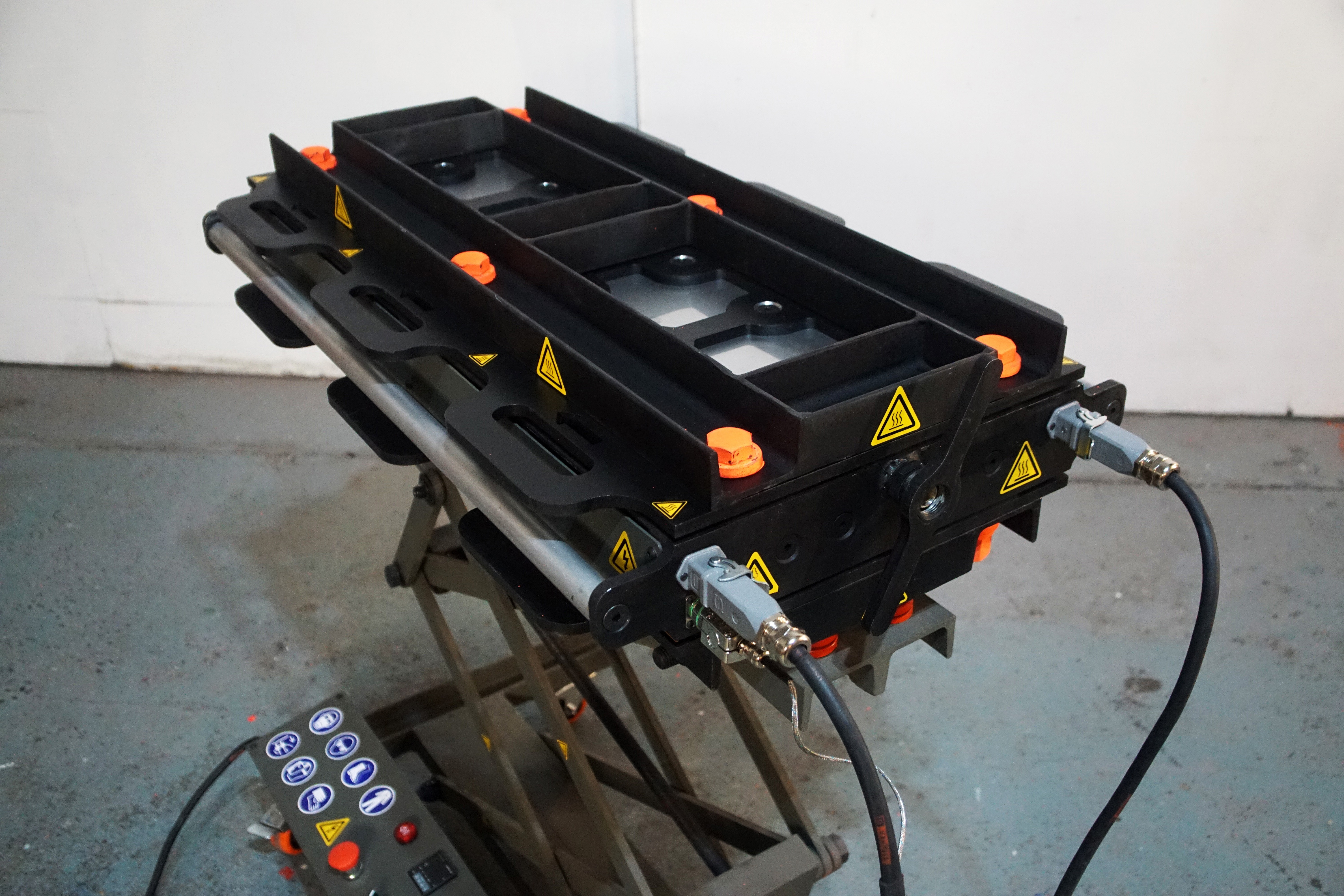
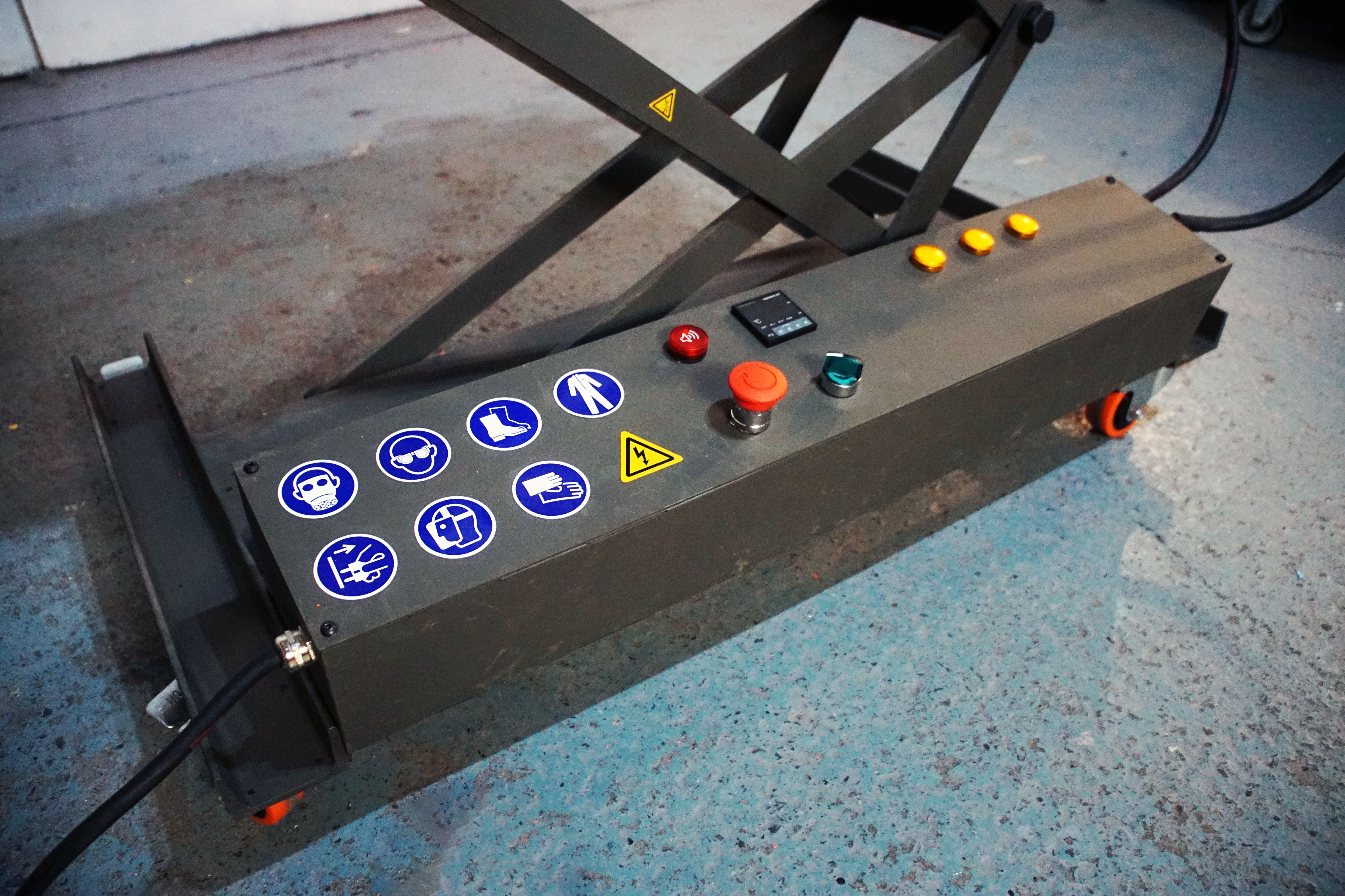
Pictures of final Mould
05/29/2022 at 13:42 • 0 comments![]()
![]()
![]()
![]()
![]()
![]()
![]()
![]()
![]()
![]()
![]()
-
Final Build
05/29/2022 at 13:39 • 0 commentsThe final build is summarised in our "How-to" Build video.
-
Build Plan
05/29/2022 at 13:35 • 0 commentsBefore building the mould, a building plan, in the format of a video script was written, to thoroughly think through and plan each step before going ahead.
Dialogue
Shot Type
📁 1. Intro Hey everyone!
White Wall
Mould, skateboards and extruder out in front of me
1
In this video I am going to show you how to build a mould which you can use to make skateboard decks from 100% recycled plastic!
The mould is open source, which means you can download all of the CAD files, Bill of materials, electronics diagrams + everything else you need to make it yourself for free.
They are made using an extrusion machine, like this one which is also open source!
So you can also build one or buy one yourself!
Check out the links in the description!
2. Breakdown So the entire mould can be broken down into three parts, the mould itself, the table and the electronics box.
White Wall
Mould out in front of me.
2
3. Mould The mould itself is made up of four main parts,
- A top and a bottom plate
- An edge structure
- A two part a support structure
- And a set of fasteners hold it all together
White Wall Mould sections on table in front of me
3.1
Top and Bottom Plates
First you're going to make the top and bottom plates.
White Wall Mould sections on table in front of me
Point at top and bottom.
3.2
You are going to need:
○ CNC Cut Aluminum Blocks Which form the top and bottom faces of the decks
○ 0.5mm Stainless Steel Washer Plates
○ 10mm Laser Cut Steel Sheets
○ M5 x 10mm Dowel Pins x8
○ M10 x 16mm Countersunk Bolts x10
○ M10 x 30mm Countersunk Bolts x10
○ M20 Thin Nuts x 8
○ Heat Resistant Paint x2
○ Safety Stickers x8
Jump between wide and Close up pointing at separate parts
3.2
First take the laser cut steel back plates. You will need to countersink all the M10 holes so that the head of the bolt lays below the surface.
Pillar drill perspective shots
3.2
On the same side you can also use the countersink to put a slight chamfer on the M20 holes to guide the bolts into place when using the mould for production. On the top plate the chamfer is on the same side as the M10 holes and on the bottom plate it is on the opposite side.
Pillar drill perspective shots
3.2
Insert the flat nuts into the hexagon cutouts, weld them in place then grind them flat.
Welding perspective shots
Grinding perspective shots
3.2
Clean the metal with degreaser and apply a layer of heat proof paint to the plates.
Painting perspective shots
3.2
Use a countersink to remove the paint in the countersunk part of the M10 holes. This is for electrical grounding and ensures that the top and bottom plates are connected to the aluminium.
Close up
3.2
Next you need to bolt the aluminium surfaces to the back plates, note that they have an orientation (The nose and the tail are different heights) so make sure to measure them carefully and align them with the arrows.
Bench
Measure with calipers
Check drawing
3.2
The top plate has a layer of stainless steel washer plates between the aluminium surface and the steel plate. This allows you to adjust the thickness of the deck by adding and removing them. They are stainless steel because you can't paint them to keep the thickness even, and they would rust if they were normal steel.
Bench
Show washers fanned out
3.2
You may need to change the bolt size if you want to adjust the thickness of the deck but by default it is 30mm on the top and 16mm on the bottom.
Bench
Show bolts
3.2
Next you can insert the dowel pins into the holes in the base plate. These are to mark where you need to drill the truck holes.
Bolting in place montage
3.2
Finally stick the safety stickers between the handles.
Close-up
3.2
Next you're going to make the edge of the mould.
White Wall
Finished part on table in front of me. Topshot of Parts.
3.3
You are going to need:
○ The CNC cut Aluminium Block
○ 2mm laser Cut sheets
○ 10mm Laser Cut Steel Sheets
○ Steel C Beams
We got our laser cut but you can also drill them by hand.
○ 1 Inch Diameter Round Stainless-Steel Stock
It is the same as the Precious Plastic Injection machine barrel so you may already have some in your workshop
○ Some Plumbing Fittings
- 2 BmSP ¾” weld on thread
- BSP ¾” swivel adapter
This thing is really cool as it allows you to attach the mould to the nozzle without rotating the whole mould.
We also laser cut a handle to attach to the adapter
○ M3 x 10mm Socket Cap Bolts x 8
○ M5 x 10mm Socket Cap Bolts x 14
○ M5 Washers x 14
○ One M8 Nut
○ M10 x 16mm Countersunk Bolts x 8
○ M10 x 40mm Countersunk Bolts x 28
○ Heat Resistant Paint
○ Metal Paint
We went for military paint as it's strong, durable, available in the same colour all over the world.
○ Safety Stickers
○ There are also some electronics components but we will explain that later in the video
White Wall
Finished part on table in front of me. Topshot of Parts.
Closeup of each item.
3.3
On one of the end plates there are some cutouts for the electronics. Around each of the cutouts there are some center points for holes marked.
Pointing at cutouts
3.3
Drill and tap each of these with an M3 thread. You will need a 2.5mm drill.
Drilling shot
3.3
Take the end plates and C beams and countersink the middle row of holes. Make sure to countersink the correct side of the end plates.
Table shot
Walk over to pillar drill
Closeup of drilling
3.3
One of the C beams has an extra hexagonal hole.
Pointing at holes
3.3
Insert an M8 nut into the hexagonal hole and tack weld it in place.
Close up grinding shot
3.3
Next we will insert the weld on threads into the hole in the frame.
Insert Shot
3.3
The insert should be 0.25mm shorter than the thread of the swivel adapter so you can tighten the swivel adapter against the aluminium block.
Measuring Shot
3.3
If it is any longer you can cut it shorter using a lathe chop saw or grinder.
Cutting Shot
3.3
Tack then fully weld the thread in place.
Welding Shot
3.3
It's Important to grind the back face flat so that the seal is tight against the aluminium .
Welding shot
3.3
Once they are welded you can make sure the thread is clean with a BSP ¾” tapping tool.
Tapping Shot
3.3
Place a small round sticker or piece of tape over each of the bolt holes to block a small area from being painted. This is to ensure all the metal components are connected together for electrical grounding.
Hold up stick,
Close up of stickers
3.3
Apply a layer of heat proof paint to the inside faces of the beams and end plates, that will contact the aluminium.
Painting Shot
3.3
Using a set square and scribe, mark the middle of the C beam on the top and bottom face
Marking Shot
3.3
Next take the bodywork mounting tabs. Tap each of the holes with an M5 thread.
Holding up to camera
Tapping in vice shot
3.3
You can also mark the vertical middle using a Caliper
Marking Shot
3.3
Take the tabs and weld them in place. The four end tabs align flush to the end plates.
Welding Shot
3.3
The two tabs that you scored are in the middle, use the score line on the tabs and the C beams to position them correctly.
Close Up
3.3
Lay your beams out around the middle aluminium block in the position they will be bolted in place.
Top Shot
3.3
The end of the C beam with the nut lines up with the end plate that has the extra hole for the thermocouple, and the edge of the aluminium block that has an extra hole.
Pointing at holes
3.3
Bolt the C beams and end plates in place. The end plates need 16mm bolts and the side plates need 40mm bolts.
Bolting shot (Top + Side)
3.3
Protect the aluminium using masking tape for the sides and cardboard for the top and the bottom,
3.3
Tack weld the four corners on the top and bottom of each part to join the four pieces together.
Welding shot (wide)
3.3
Then fully weld the four corners of the mould.
Welding shot close
3.3
Grind the top and bottom welds flat.
Grinding shot
3.3
Next take your swivel adapter and weld the handle on to the freely rotating part.
Welding shot
3.3
Grind the front face flat so the bodywork panel mounts on correctly.
Grinding shot
3.3
Check that the tabs align with the side panels by bolting them in place. If not you will need to cut them out and re align them.
Boling panel in palace
3.3
Screw the swivel adapter into the end plate.
Screwing Shot
3.3
Clean the frame with degreaser and apply a layer of heat proof paint. Stick a small round sticker around the bolt holes on each of the body work mounting tabs.
Degreasing
Stickers Painting Shot
3.3
You can also paint the bodywork panels, again cleaning them with degreaser and placing a small sticker over each of the bolt holes. For the bodywork panels we just used regular metal paint.
Degreasing
Stickers Painting Shot
3.3
You can leave the bodywork panels off now as you will need to install some electronics later on.
3.3
Next you're going to make the handle.
Holding up handles
3.3
Take your 1 inch diameter stainless steel rods.
Cutting on chop saw shot
3.3
Cut them to length using a chop saw or grinder.
Cutting on chop saw shot
3.3
Using a lathe drill and 40mm deep 9mm diameter hole at the end of each of the rods.
Lathe shot
3.3
Then tap the holes with an M10 tap.
Tapping shot
3.3
If you cannot find stainless steel rods, regular steel will also work but you will have to apply a layer of paint to protect it from rust.
Paint shot
3.3
You can also leave the bodywork handles off now as you will need to install some electronics later on.
Next you're going to make the support structures.
White Wall
Finished part on table in front of me. Topshot of Parts.
Closeup of each ite
3.4
You are going to need:
○ Steel C Beams
○ Heat Resistant Paint (3)
○ Safety Stickers (3)
3.4
Take the four longer beams. On two of them, countersink the M20 holes on the inside face. On the other two, countersink the holes on the outside face.
Table shot,
Countersinking closeup shot
3.4
Next weld the frames together.
Welding shot
3.4
Note that the top and bottom sections have the shorter beams in different orientations, and have the countersinks facing a specific way. Double check in the drawings to make sure you weld them correctly. The bottom sections have holes laser cut in.
Closup of countersinks
3.4
To align the middle piece use a ruler and scribe to mark the center of each piece.
Closup of marking
3.4
Tack weld the parts together, check that the holes align with the holes on the top and bottom plates of the mould. If they do not adjust them with a hammer or cut them and re tack them in place.
Welding shot
3.4
Once you are sure everything is aligned, fully weld each section.
3.4
Make sure the welds on faces that contact the body of the mould are grinded flat.
Grinding shot
3.4
Clean the metal with degreaser and apply a layer of heat proof paint to both sections.
Paint shot
3.4
Finally attach the safety stickers to the edge of the frames.
The final part of the mould body is the fasteners which will hold the whole thing together.
White Wall
Finished part on table in front of me. Topshot of Parts.
Closeup of each item.
3.5
We went for M20, nice and big. Make sure to get 12.9 grade steel, they are strong and durable.
3.5
You are going to need:
○ M20 x 250mm Hex Bolts (6)
○ Extra Thick M20 Washers (12)
○ M20 Flange Nuts (6)
○ Fluorescent Paint (1)
Spray the nuts, the washers and the heads of the bolts fluorescent orange so that they are easy to find.
Painting shot
3.5
4. Table Next you're going to make the table.
White Wall
Finished part on table in front of me. Topshot of Parts.
Closeup of each item.
4.1
The table can be split into three main sections,
- A Base
- The Legs
- And the top
4.1
Base
You will start with the base and work up.
White Wall
Finished part on table in front of me. Topshot of Parts.
Closeup of each item.
4.2
You are going to need:
○ Steel C Beams
○ Heavy Duty Caster Wheels with Breaks (4)
○ M5 x 10mm Socket Cap Bolts (32)
○ M5 Washers (32)
○ Metal Paint (2)
4.2
On the foot beams there are some centre points for the holes marked.
Close up of centre points
4.2
Drill and tap each of these with an M5 thread. You will need a 4mm drill.
Drill and tap shot
4.2
On the two foot beams, mark the centre of the larger outside face.
Close up marking shot
4.2
Weld the two longer beams together. You can use the long M20 bolts to help align them for clamping.
Welding shot
4.2
Now position the two foot beams, with the centre mark using an L angle and weld them in place.
Wides shot
4.2
Place a small round sticker or piece of tape over each of the bolt holes to block a small area from being painted.
Close up
Next clean the metal with degreaser and apply a layer of metal paint.
Painting shot
4.2
Once it has dried attach the caster wheels.
Bolting on caster wheels
4.2
Next we are going to make the legs.
White Wall
Finished thing in front of me.
4.3
You are going to need:
○ 10mm Laser Cut Steel Sheets
○ Steel C Beams
○ M10 x 40mm Countersunk Bolts (4)
○ M10 Locknut (With Flange) (4)
○ Large M10 Washers (8)
○ M20 x 80 Hex Bolts (4)
○ M20 x 250 Hex Bolts (4)
○ M20 Lock Nuts (8)
○ M20 Washers (38)
○ Thin M20 Washers (4)
○ An M20 Nut (1)
○ An M20 Flange Nut (1)
○ An M20 Dome Nut (1)
○ An M20 Bar Stud (1)
○ An M20 x Threaded Rod (1)
○ Metal Paint (2)
○ Fluorescent Paint (1)
White Wall
Finished part on table in front of me. Topshot of Parts.
Closeup of each item.
4.3
Start by taking the small C cut beams
Welding shot
4.3
Weld the end plates onto the C beams.
4.3
And grind the welds flat
4.3
You will notice one of the beams has a hexagonal hole inside. Insert the M20 Bar Stud into the hole and weld it in place.
Close up of hole
4.3
Grind the welds flat
Close up
4.3
Clean the metal with degreaser and apply a layer of metal paint to the beams and the strips.
Countersink shot
4.3
On the inside of two of the leg pieces there is an M10 hole. Countersink the hole so that the head of the M10 countersunk bolts lays below the surface.
Close up of M10 hole
4.3
Take the M20 threaded road and weld A nut on to the end to make a really long bolt
Closeup of nut, weld
4.3
and grind the head smooth.
Spray the end of the bolt, one of the M20 Washers and the M20 Dome nut with fluorescent paint.
Painting shot
4.3
Referring to the drawing, from the base up, start to assemble the strips. You can apply a bit of engine grease or WD-40 to all of the bolts.
Painting shot
4.3
Insert the bolt through the C beam with the round hole in.
Wide assembly shot
4.3
Add an M20 washer and a flange nut to the middle of the beam.
4.3
Thread the rod through the M20 Bar Stud at the other end of the C Beam.
4.3
Now move the flange nut and washer against the inside face of the C beam. You want it to be a little bit loose, so that the rod can rotate freely.
Close up of welding, rotate rod
4.3
Weld it in place.
4.3
Finally tighten the M20 acorn nut on to the end of the M20 Threaded Rod.
Close up of acorn nut
4.3
Top
Next we are going to make the top
White Wall
Finished thing in front of me.
4.4
You are going to need:
○ Steel C Beams
○ Heavy Duty Compression Springs (6)
○ M20 x 80mm Hex Bolts (6)
○ M20 Washers (12)
○ M20 Lock Nuts (6)
○ Metal Paint (2)
○ Safety Stickers (2)
White Wall
Finished part on table in front of me. Topshot of Parts.
Closeup of each item.
4.4
Take the two C beams and weld them together. You can use the long M20 bolts to help align them for clamping.
Wide shot
4.4
Grind the welds flat
4.4
Clean the metal with degreaser and apply a layer of metal paint to them.
Close up of cleaning
4.4
You can also apply a layer of orange paint to the springs.
Close up of paining
4.4
Bolt the top of the table to the top of the legs.
Close up
4.4
Finally stick the safety stickers down each side of the legs.
Close up
4.4
5. Electronics Finally you are going to install the electronics
White Wall
Finished part on table in front of me. Topshot of Parts.
Closeup of each item.
5.1
You are going to need:
○ 2mm Laser Cut sheets
○ M5 x 10mm Socket Cap Bolts
○ M5 Washers
○ M5 Nuts
○ M3 x 10mm Socket Cap Bolts
○ Metal Paint
○ Safety Stickers
○ Electronics Components
5.1
There are quite a lot of electronics components and they are quite specific so you can check the BOM for the full list.
5.1
Enclosure
Next we are going to make the Enclosure.
White Wall
Finished box in front of me
5.2
First weld the laser cut parts to make the enclosure.
Wide welding shot
5.2
And grind the external welds flat
Tap the four bolt holes with an M5 thread.
Close up
5.2
Place a small round sticker or piece of tape over each of the bolt holes to block a small area from being painted. We also covered each of the internal holes in the box so that each electronic component is individually grounded.
Close up
5.2
Clean the metal with degreaser and apply a layer of metal paint.
Painting shot
5.2
Once it has dried, install the electronics components in the box.
Top shot montage
5.2
This part is very complicated so be sure to follow the circuit diagram.
5.2
Next attach the power supply cables to the enclosure.
Finally we are going to install the safety stickers on the front cover
Edge
Next we are going to install the electronics components in to the mould edge.
White Wall
Finished part on table in front of me. Topshot of Parts.
Closeup of each item.
5.3
Install the quick connectors for the cartridge heaters and thermocouples on to the end plate using the M3 socket cap bolts.
Close up of both
5.3
Next insert the cartridge heaters into the aluminum block.
Side shot
5.3
Apply a small blob of heat resistant glue around the outer edge before inserting them.
Close up of applying glue
5.3
The cartridge heaters are 380V so each is wired in parallel between two of the phases.
Wiring shot
5.3
Split the cartridge heaters evenly, in groups of 21, 21 and 22 between the phases. You can color code each hole with a marker to make sure you wire them correctly.
5.3
Make sure that the phase that has the extra cartridge heater is not the phase that powers the components inside the enclosure.
They are joined by splicing the wires then covering them with PTFE Shrink wrap.
Close up
5.3
Remove the hub from the cartridge heater connector and attach the three phase cables to the terminals then re-install the hub.
Close up
5.3
Attach a ground cable from the ground terminal of the connector to the M5 hole on the nozzle plate. And one to the rear of one of the port mount holes.
Close up
5.3
Remove the hub from the back of the thermocouple connector, cut the thermocouple cable with enough length that it can reach the M8 Nut, plus a bit more.
Close up
5.3
Thread the thermocouple into the M8 Hex Nut.
Close up
5.3
Install the bodywork panels.
Wide shot
5.3
Bolt the handles in place using 40mm M10 bolts.
Bolt shot
5.3
Finally stick the safety stickers on the end plates and the bodywork panels.
Close ups
5.3
6. Assembly So now we have all the components we need and we are going to assemble the mold.
White wall
Finished part on table in front of me. Topshot of Parts.
Closeup of each item.
6
Take the bottom support structure and bolt it to the top of the table with the springs between the table top and the support structure.
Wide
6
Place the bottom, middle, then top of the mould on the table.
6
Then place the top support structure on top of the mould.
6
Bolt the whole structure together.
Close up
6
Install the electronics box on the base of the table.
Wide shot
6
It has four bolts on the underside, and you have the choice to install it flat or at an angle.
Close up of bolts
6
Attach the power supply and thermocouples.
6
7. Make A Deck To use the mould, first we are going to open it and apply a layer of silicone oil to the inside faces using a clean cloth.
White wall
Both next to each other
Not attached
Mould open
Close the mould and tighten the bolts. Using a torque wrench or impact driver.
Close Up
7
Pre heat both the extruder and the mould
Close up switches and PIDs
7
Make sure you are wearing the correct PPE
Put on
7
Use the adjustment bolt to alight the extruder nozzle to the mold entry.
7
Using the handles, attach the extruder nozzle to the end of the extruder.
Wide shot
7
Feed the plastic into the extruder and wait for the mold to fill.
Pouring shot
7
You tell when the mould is full by watching the small hole at the opposite end to the extruder.
Close up
7
Wait for the mould to cool
Clock
7
And open it up!
Opening wide shot
7
If it gets stuck there is a small groove around the edge between the C beams and the top and bottom plates. You can use a crowbar to lever it open.
Same shot as before, wide.
7
As a last resort there are also some release holes, screw an M20 bolt in to each of them, tightening them one by one in circular pattern
Close up
7
Gently break the extra material and lever the deck out of the mould
Lever
7
And there it is!
Hold up deck
7
The next step is to hit the street!
Skating shots
7
8. Outro Our next video which shows you how to make decks using the mould!
White Wall
Finished mould in front of me
8
Project RPSD is a non profit organisation publishing open source plastic recycling research online for free.
If you would like to support the development of this project follow the URLS below to like us on Facebook, follow us on Instagram, join our mailing list, make a donation and become a supporter on Patreon.
Sharing our posts and spreading the word about our project opens a lot of doors for us! We are also very keen to hear about any collaborations or opportunities you guys see!
Thanks for watching!
URLS
8
-
Design Decisions: V3 Prototype 1
05/29/2022 at 13:28 • 0 commentsRPSDM V3 Design Decisions
PRE-BUILD CAD WALKTHROUGH VIDEO. (Video does not represent the final version as some changes were made.)
Design Decisions
- Colour Code Fasteners
- Passive
- Interactive (neon)
- NATO green paint (Available everywhere in the world)
- Deck Strength
- Thicker nose and tail
- Thicker in the middle (T Beam)
- Steep concave (Pipe)
- Thick patch on nose and tail curve up (Prevents wearing)
- Springs to allow nozzles to move slightly when coupling with the nozzle plate
- Hold thermocouple
- Nut welded in the beam
- Differentiate nose/tail
- Arrow on a horizontal plate
- Change Deck Thickness
- ‘Washer” Plates
- Attach to Extruder
- Quick Release: Big Laser cut handle welded to the nut
- Find the right plumbing head: Swivel connector
- Open Mould
- Nuts on top and bottom plate for “Release Bolts”
- Enough gap between the side frame and horizontal plate to fit in the crowbar
- Heat Mould
- Cartridge heaters (380, 16A) in holes downside of “Deck Edge”
- Fit aluminium sections in
- Fillet inside gradual
- 0.2mm contour between deck top/bottom face and deck edge (Check V4 file)
- Slow to bolt mould together
- Drill with a long socket
- Countersink holes on steel plate
- Mark Holes For Trucks
- 5mm Dowel inserts in the mould
- Stop Mould Bend
- C beams (Out)
- 80x40 frame on top (C Beams top also??) Then all C Beams
Part Numbers Template
before the dot is only for assemblies, assemblies always end in .00
X000.00 - in this case, X is for upper-level assemblies
0X00.00 - in this case X is for sub-assemblies
00X0.00 - in this case X is for sub-assemblies and so on
0000.xx After the dot is the part number
EXTPRO-V1 0000.00
EXTPRO-
V1
0
0
0
0
.
0
0
Machine Name
V#
Part
Assembly
Sub Assembly
Part
RPSDM-
V3
-Deck -Mould -Electronics Enclosure
-Table
-Mould Top
-Mould
Bottom
-Mold Top
Support Frame
Bolt
Beam
RPSD: Recycled Plastic Skateboard Deck
Tackling plastic waste, democratizing access to skateboarding and proving to people what products made from waste can really do.