 Timo
Timo-
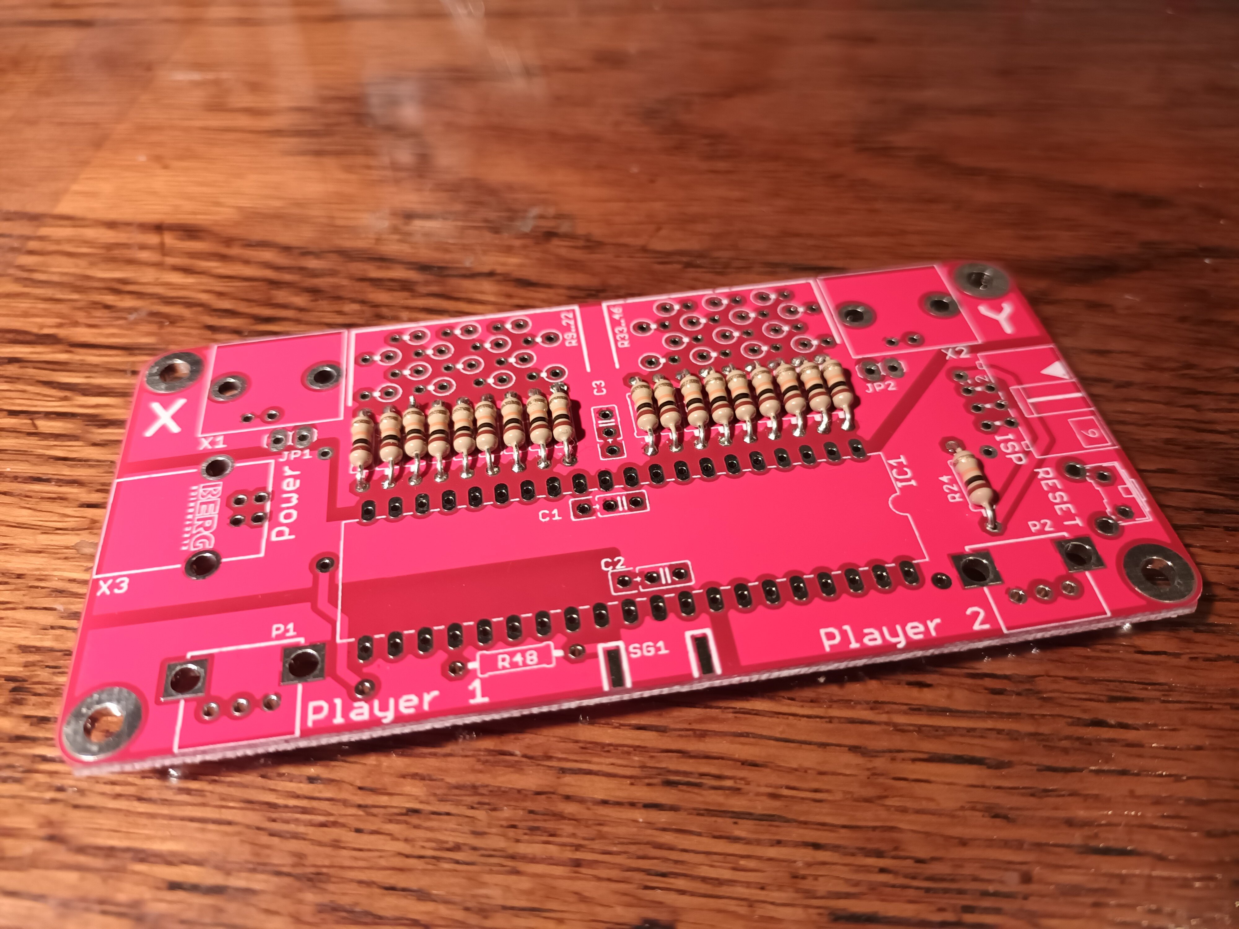
1Put in and solder 10k Ohm resistors at R1...R8, R23...R32 and R47
![]()
Put 10kOhm resistors in the PCB and solder them as depicted in this image. If you are not sure about something, look for the assembly plan and the bill of material in the project documentation.
Tip: If you want it to look nice, put all resistors in the same direction. Otherwise the direction doesn't matter.
-
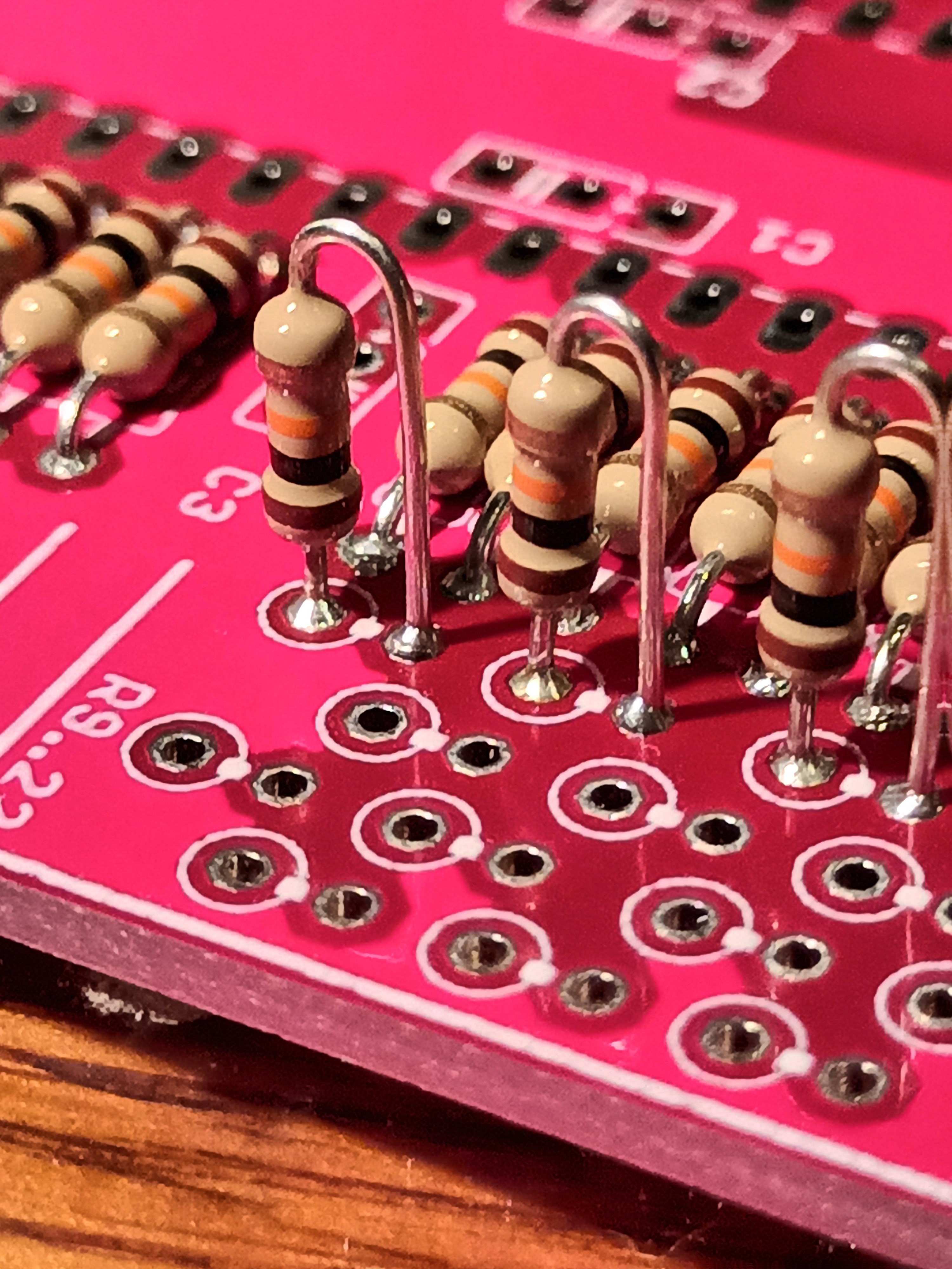
2Put in and solder a 500 Ohm resistors at R48
![]()
That is how it should look when you are done. Bonus points if you can spot the difference ^^.
-
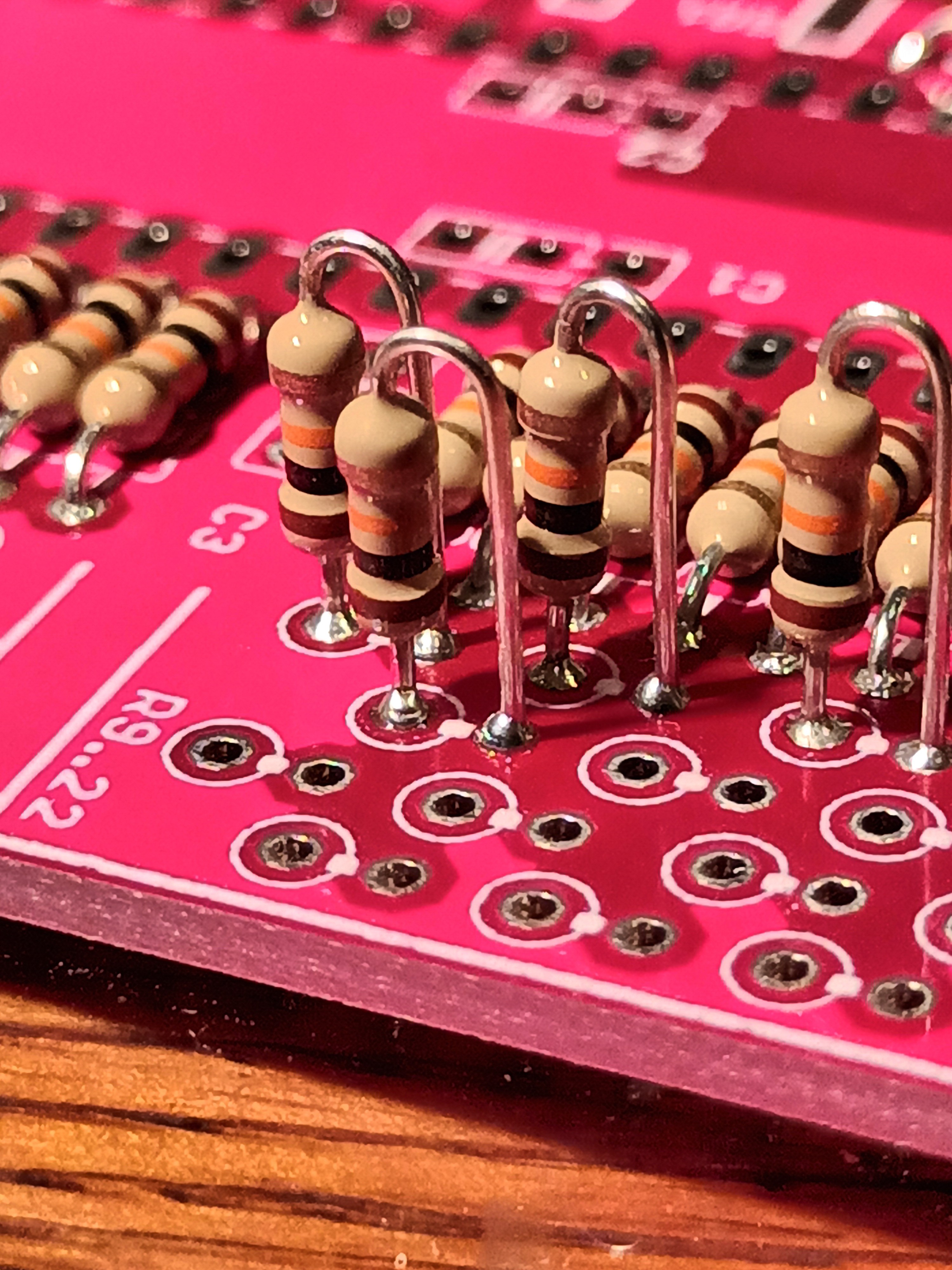
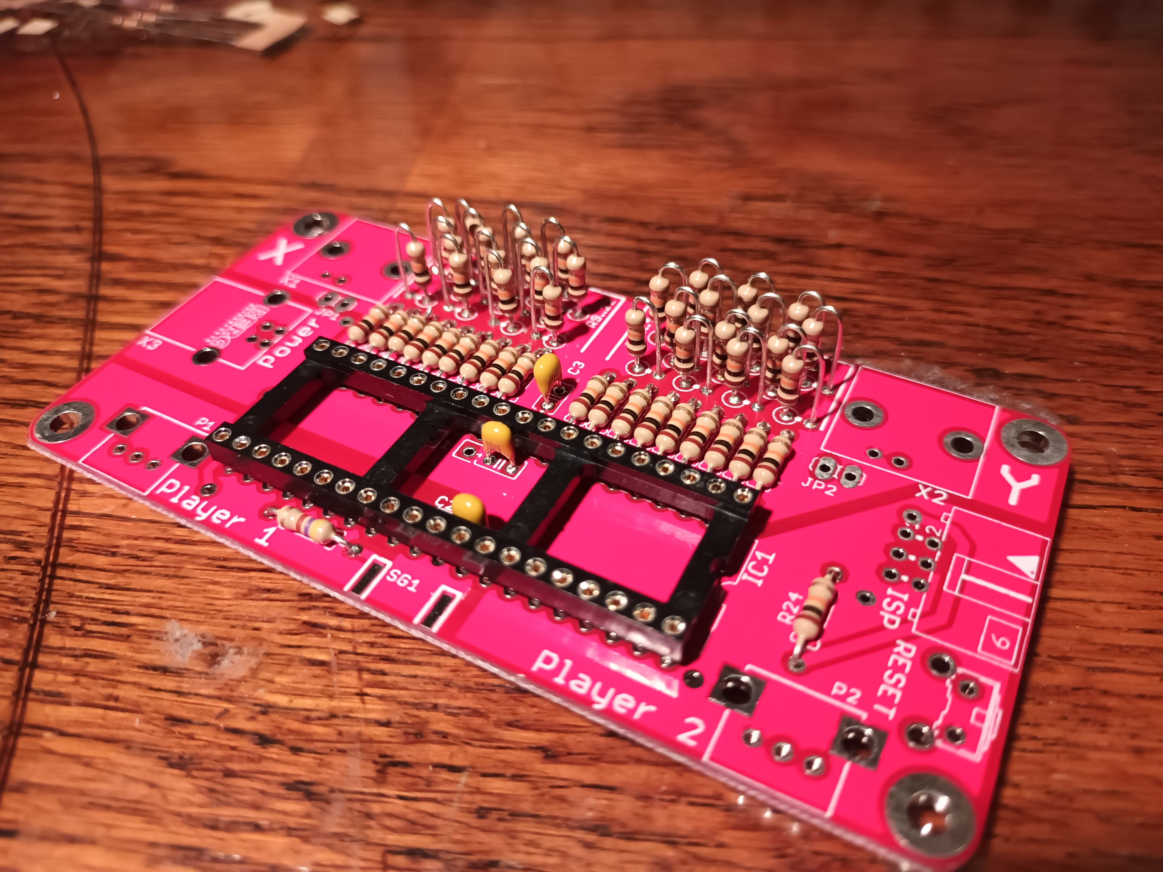
3Put in and solder 10k Ohm resistors at R9...R22 and R33...R46
![]()
Now solder all the up-right resistors. All of these resistors are 10k Ohm resistors.![]()
It is hard to see, but from this picture you should be able to guess where to put these resistors. This is before .....
![]()
... and this is after soldering.
-
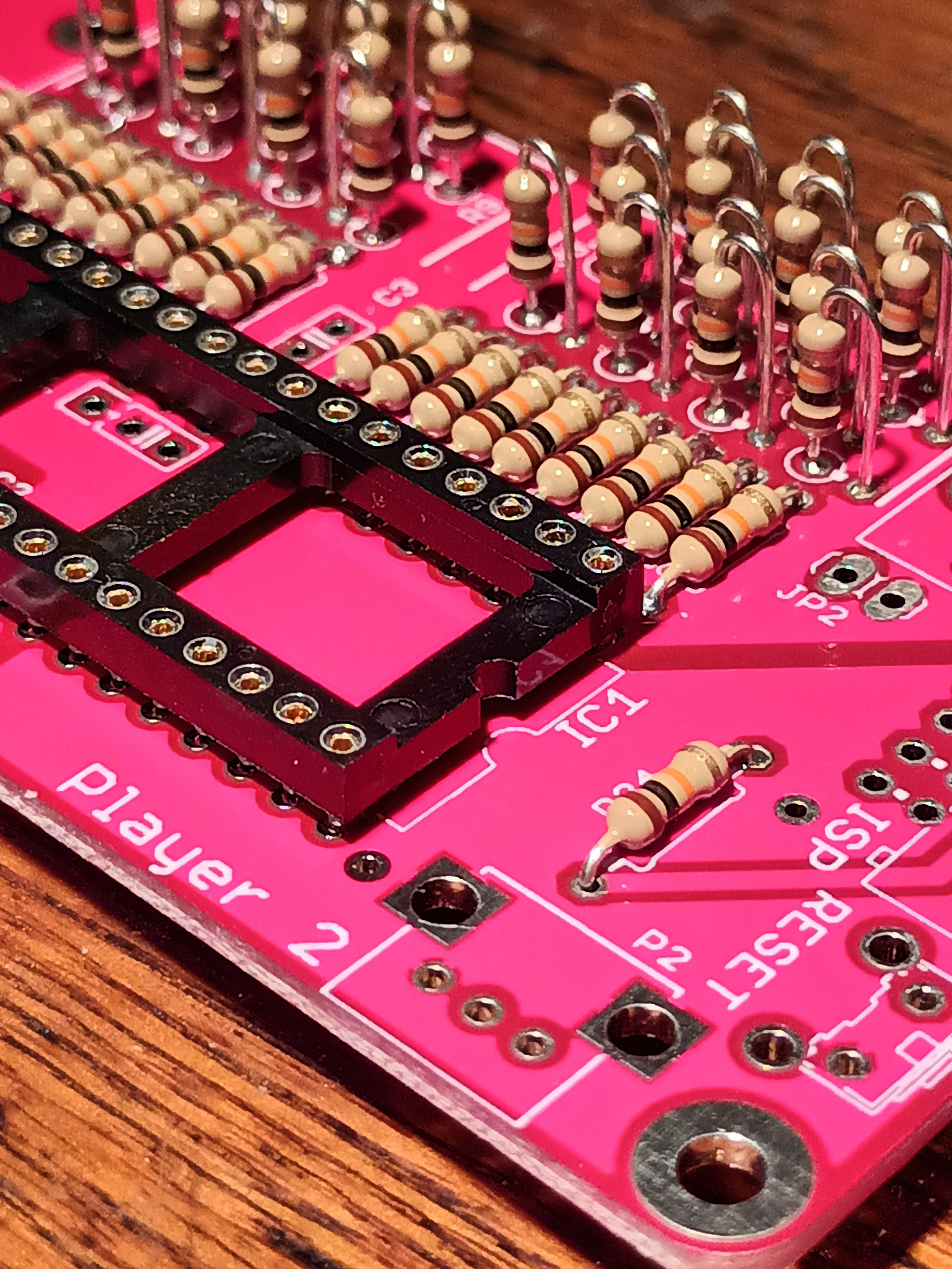
4Solder the socket for IC1
![]()
This is how it should look. Keep in mind to put the socket into the right direction. The notch in the socket should align with the silkscreen on the PCB.
![]()
-
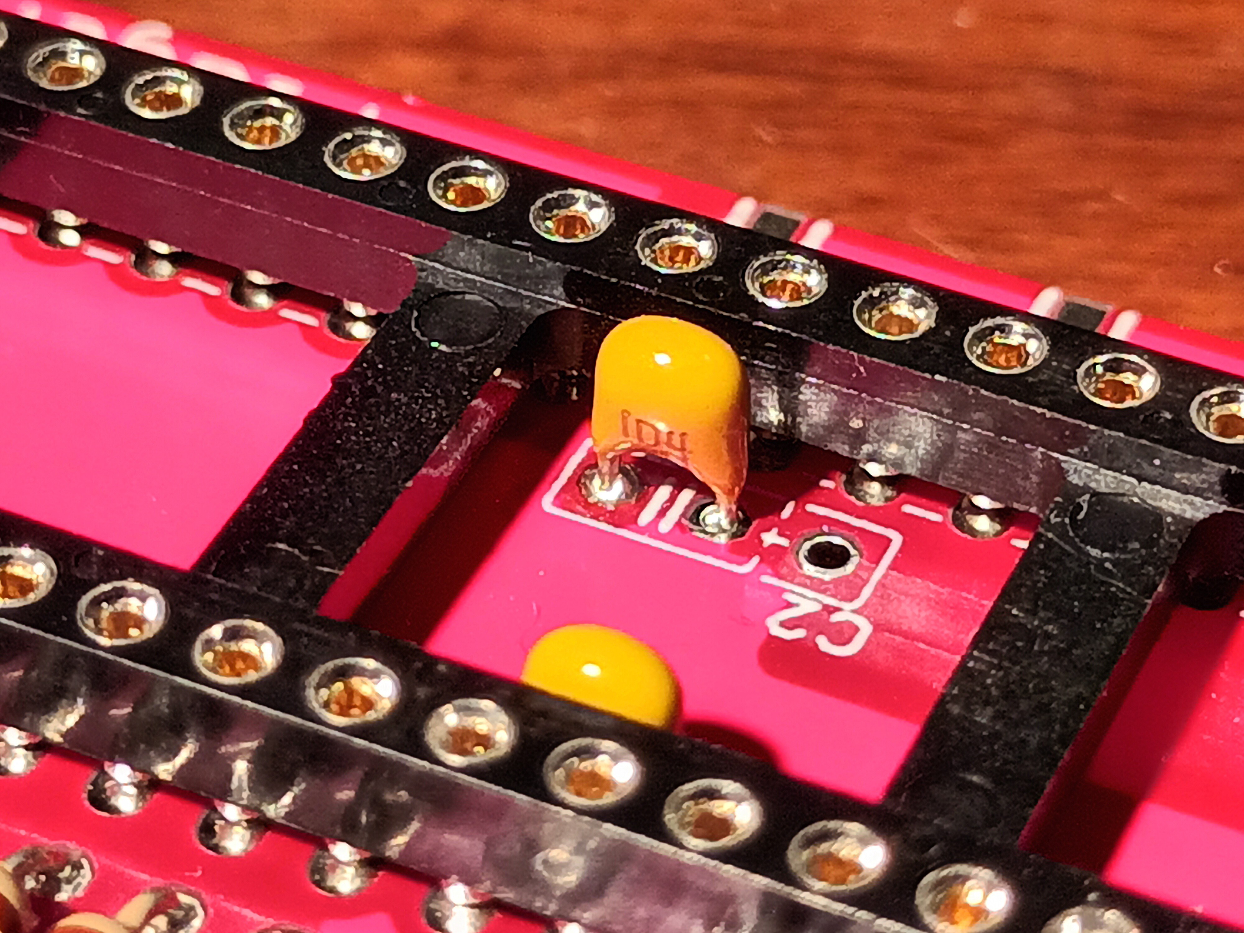
5Solder in 100nF for C1, C2 and C3
![]()
Yes, this is correct. C1 and C2 should be inside the socket, so when you apply IC1 later they will no longer be visible.
![]()
This is how you solder C1.
![]()
Now C2, like this.
![]()
... C3 ...
-
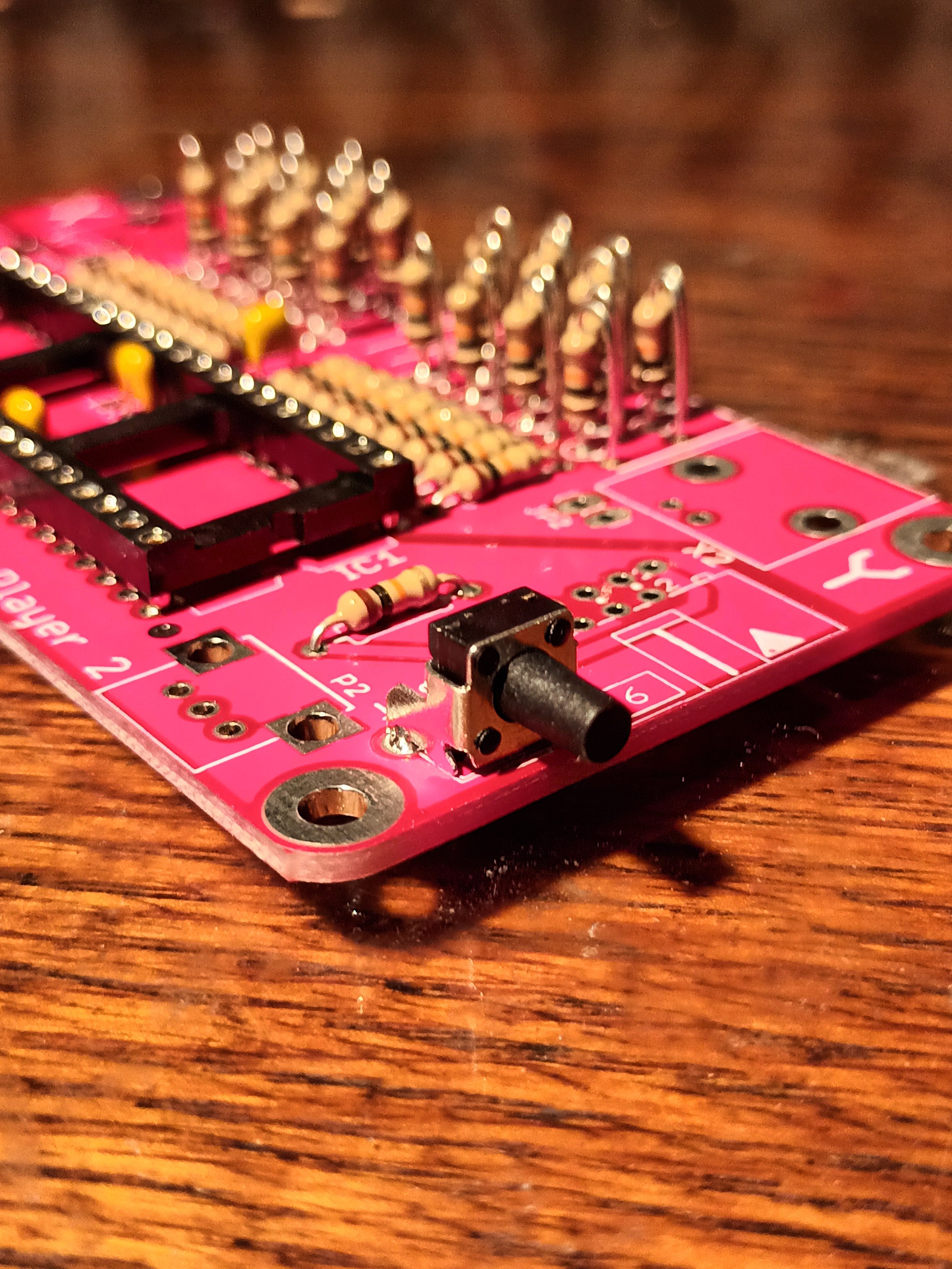
6Solder in the Reset button
![]()
-
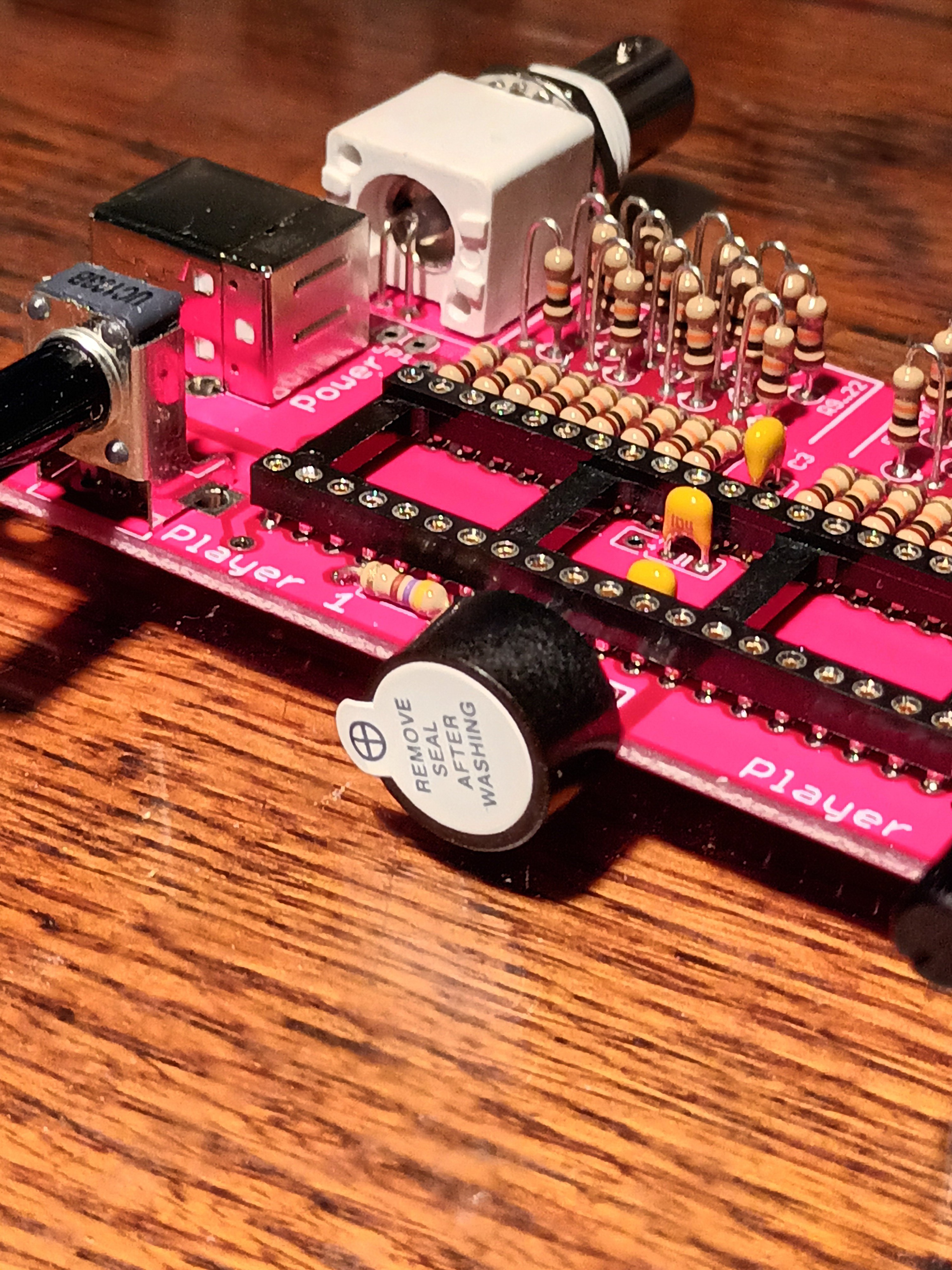
7Put in and solder all connectors and potentiometers
![]()
Tip: If you don't like the BNC connectors you can solder in pinheaders at JP1 and JP2. Then you can hook your probes directly to the PCB
-
8Solder the speaker to the PCB
![]()
Just solder the speaker directly to the pads on the pcb like a smd component. The polarity does not matter.
![]()
This is how it looks from behind.
-
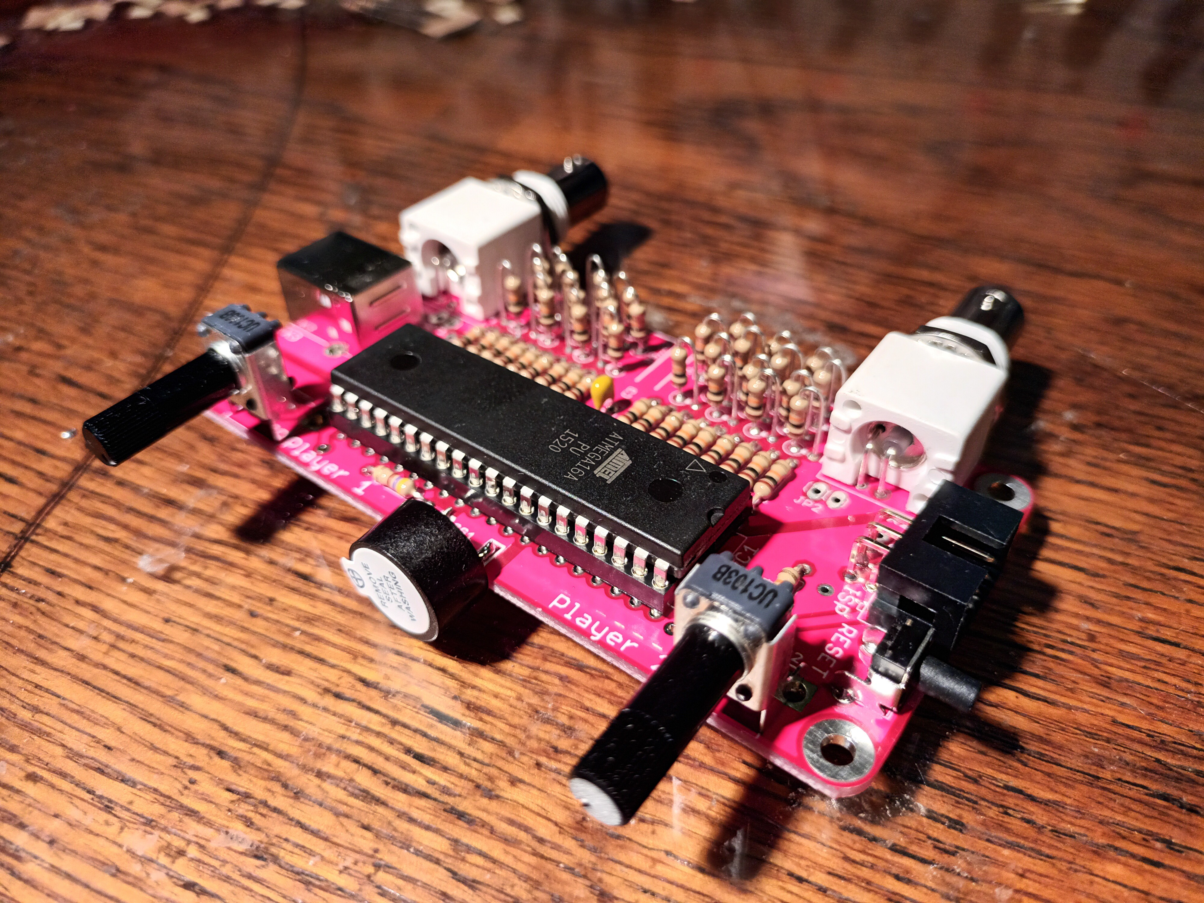
9Put in IC1.
![]()
If you got kit from me your µC should be pre-programmed. Other wise you have to program the µC later via the ISP header. Look for the software in project documentation.
-
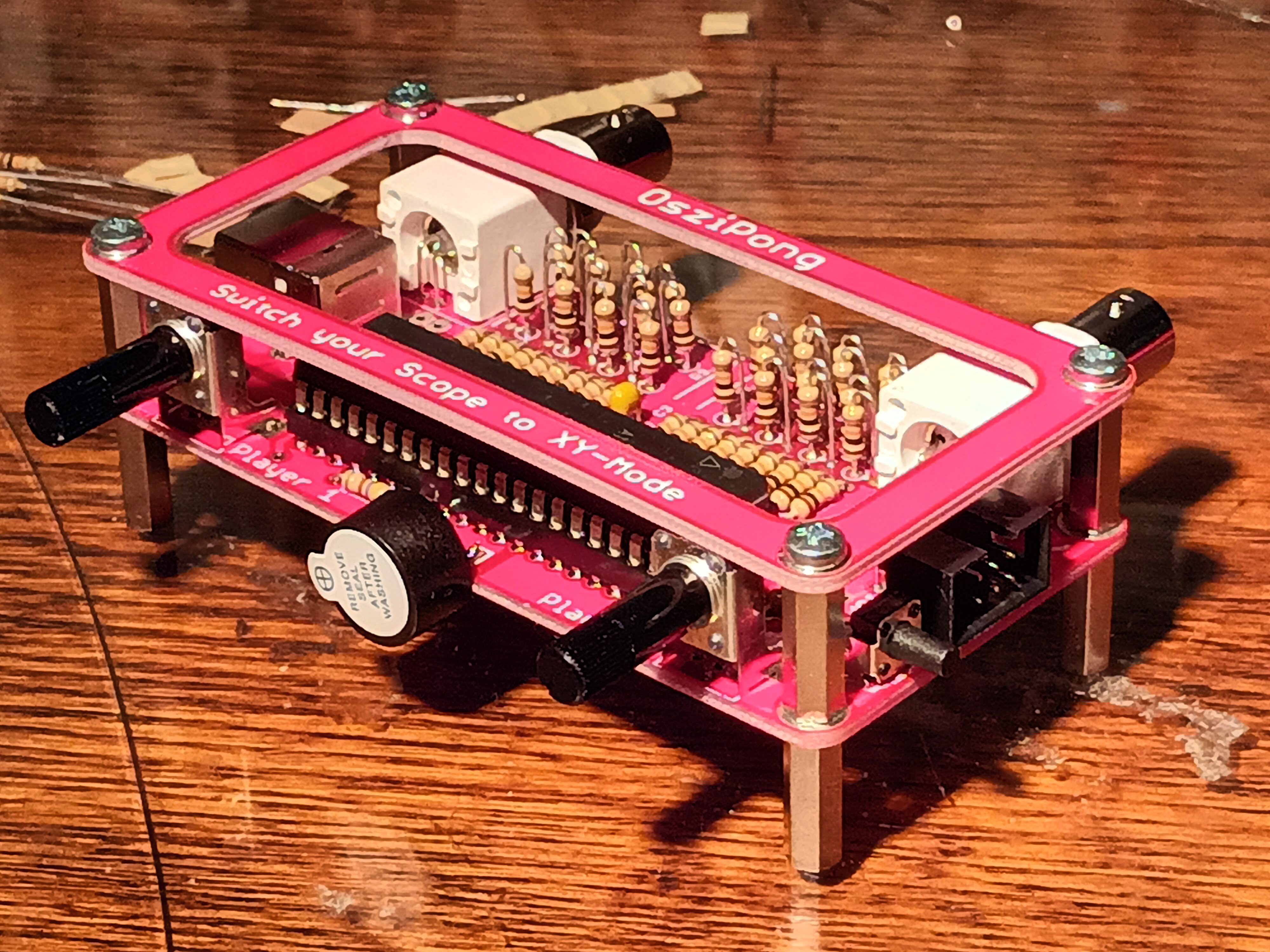
10Mount the feet and the top cover. Done!
![]()


Discussions
Become a Hackaday.io Member
Create an account to leave a comment. Already have an account? Log In.