 Peter Walsh
-
1Duct-tape prototype
First prototype, made from DuctTape.
The first prototype is quite an easy build, took me all of 2 hours start to finish (including images for documentation and some CAD work for the laser.
Tools needed
- Laser cutter
- Spring clamps (about 6, more or less)
- A needle
- Soldering iron
- Side cutters
- Wire strippers
- 3 volt power supply (for testing)
- DVM (for testing)
- Hot glue gun
Materials needed
- 10-conductor ribbon cable
- Pressed cardboard (for jig)
- 6 pager motors
- PCB alerter
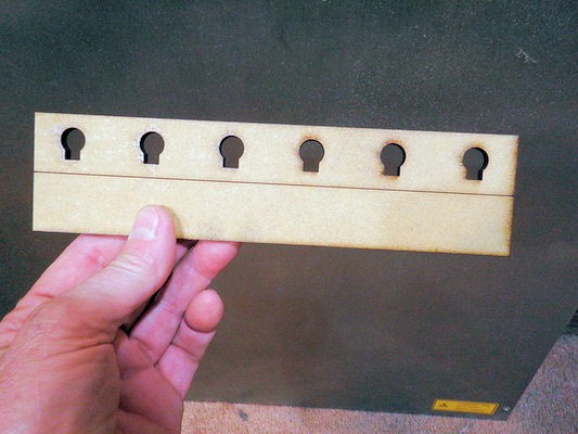
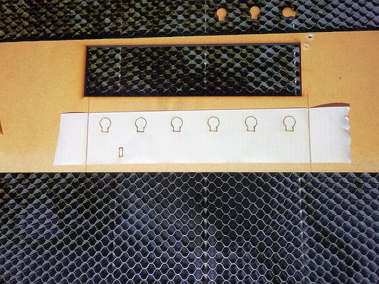
Step 1: Cut out a holding jig.
Cut out a holding jig for the motors. I found that 1/16" pressboard was a tad too thick, I think something slightly thinner would be better. The form is the witch of a strip of duct tape, and has a centerline for alignment.
![]()
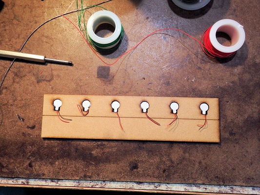
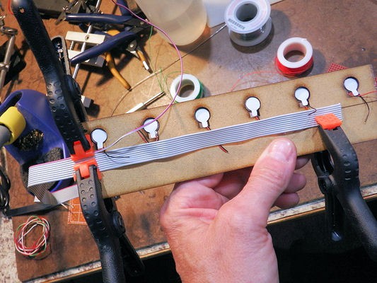
Step 2: Place boards in the jig
![]()
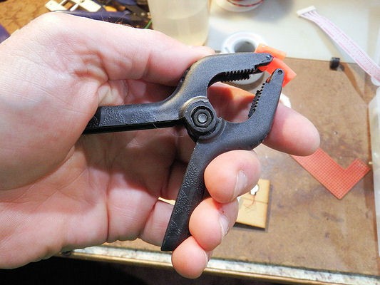
Step 3: Grab a handful of spring clamps
Harbor Freight sells these, and the smaller ones (below) for a song. You'll need about a half dozen of these.
![]()
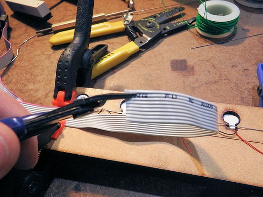
Step 4: Peel back and strip the ground wire
Using the side cutters, separate the pin 1 conductor from the ribbon cable
![]()
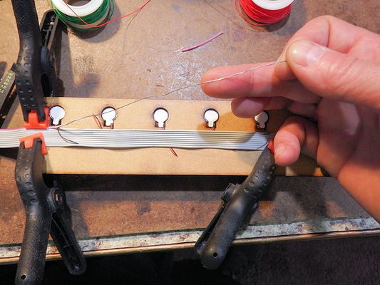
Peel back the pin 1 conductor all the way to the left end of the project
![]()
Strip the peeled wire back to the beginning, and twist the free strands together.
![]()
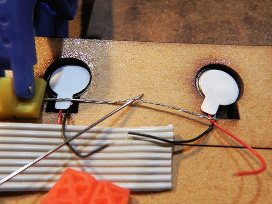
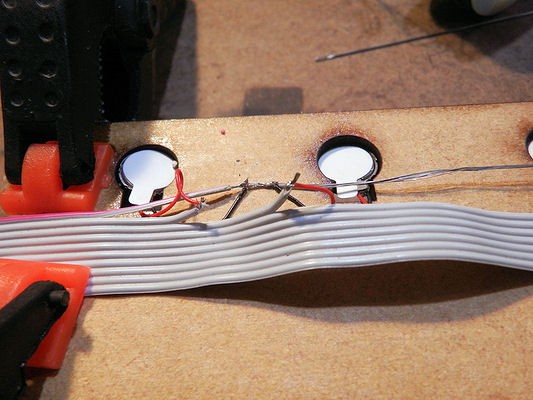
Step 6: Solder all motor ground connections
Use the needle to spread/make a hole in the twisted ground strands.
![]()
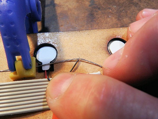
Place the motor ground wire in the hole
![]() Touch your soldering gun to the solder to get a small blob of solder, then touch the molten blob to the motor wire and ground strands. This will solder the motor ground to the grounding wire.
Touch your soldering gun to the solder to get a small blob of solder, then touch the molten blob to the motor wire and ground strands. This will solder the motor ground to the grounding wire.![]()
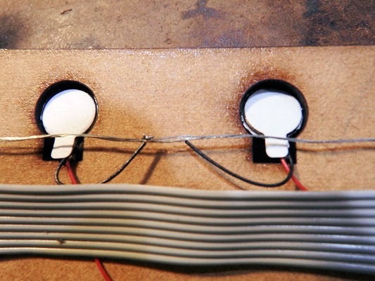
Repeat for all the other motor ground wires.
![]()
Step 7: Solder all motor control wires
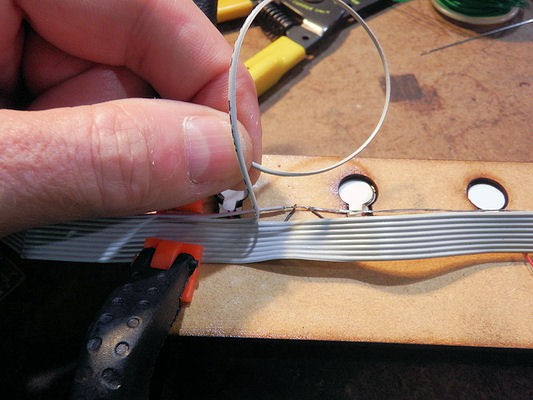
Using the side cutters, separate one control wire and peel back to the first motor
![]()
Cut and strip the end
![]()
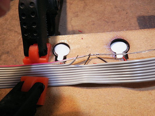
Touch your soldering iron to the solder to get a small dollop of solder. Then hold the motor wire to the control wire with a pair of tweezers and touch the molten blob to the wires to make the connection.
![]() Continue until all motors are connected to the ribbon cable. Using multiple spring clips makes this easier. Note that the wires are peeled back only as far a needed, only as far as the motor the need to attach to.
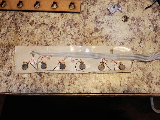
Continue until all motors are connected to the ribbon cable. Using multiple spring clips makes this easier. Note that the wires are peeled back only as far a needed, only as far as the motor the need to attach to.![]()
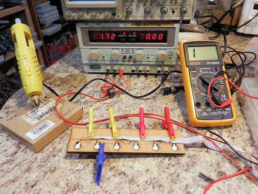
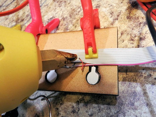
Step 8: Test and seal your circuit
Warm up the hot glue gun.
Using a power source and DVM, test that each motor is connected and works. Make repairs as needed.
![]()
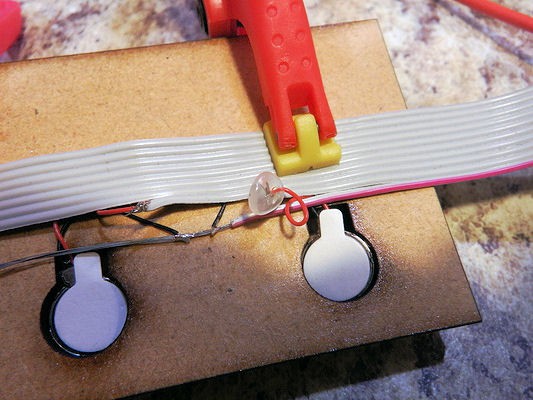
As each connection is tested, place a small blob of hot glue on the solder joint. The hot glue will serve as a strain relief on the joints, making it less likely for the wire to break.
![]()
The hot glue blob should look like this:
![]()
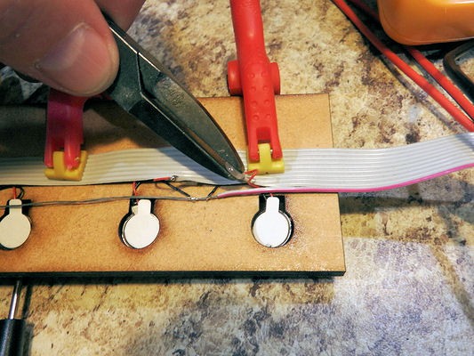
After about a minute, press the blob flat using a pair of smooth-jawed pliers. You have to wait a full minute, so that the glue is no longer sticky, but not completely cooled or the glue will fracture.
![]()
A flattened strain-relief blob:
![]() Repeat for all motor connections
Repeat for all motor connections![]()
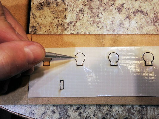
Step 9: Make the duct-tape cover
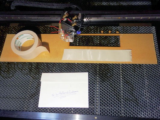
Tear off a piece of duct tape longer than the form, and place it in the laser for cutting.
![]()
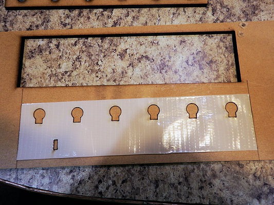
The file will automatically trim the tape to the correct length.
![]()
Using a probe, carefully remove the inserts from the duct tape.
![]()
![]()
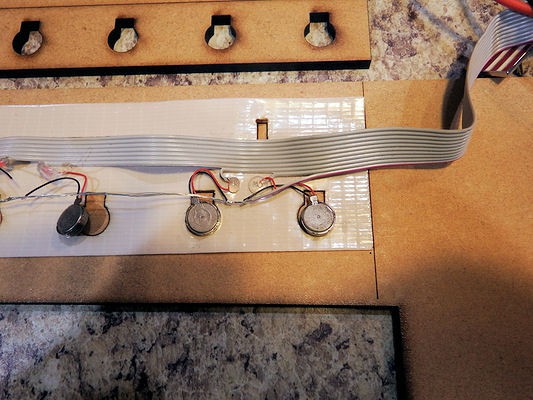
Step 10: Final assembly
Place the completed motor/ribbon cable harness over the tape cover.
![]()
Press the flattened strain relief blobs into the duct tape. Make sure everything looks good.
![]()
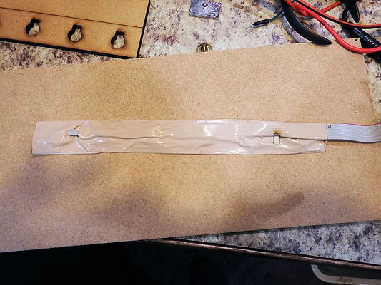
Fold the top of the duct tape over the lower half, and press firmly. Run your fingers along the entirety of the tape, making sure that the two halves press together. Thread the remaining 3 ribbon cable wires through the rectangluar window.
![]()
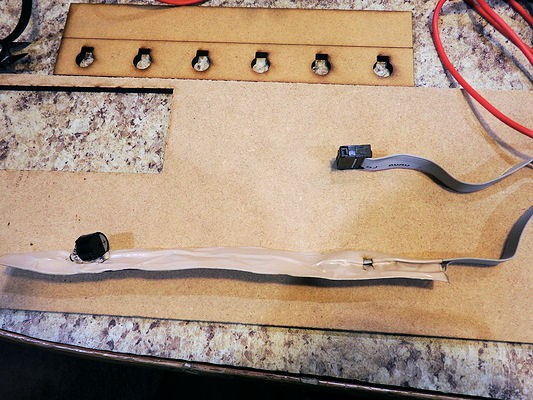
Solder a PCB mount alert onto 2 of the 3 unused ribbon cable wires.
![]()
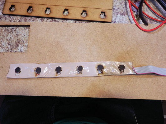
The completed unit looks something like this:
![]()
 Touch your soldering gun to the solder to get a small blob of solder, then touch the molten blob to the motor wire and ground strands. This will solder the motor ground to the grounding wire.
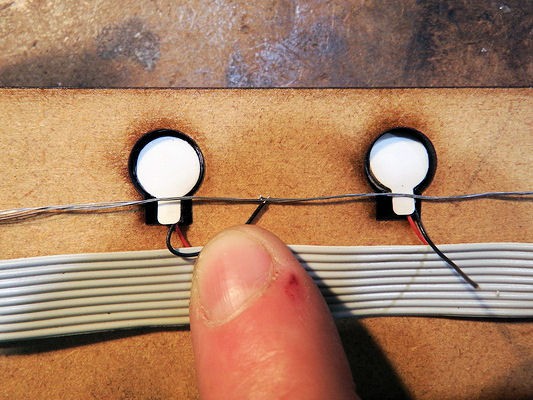
 Continue until all motors are connected to the ribbon cable. Using multiple spring clips makes this easier. Note that the wires are peeled back only as far a needed, only as far as the motor the need to attach to.
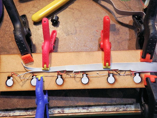

 Repeat for all motor connections
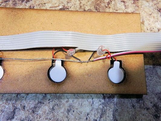
Discussions
Become a Hackaday.io Member
Create an account to leave a comment. Already have an account? Log In.