Peter Walsh
-
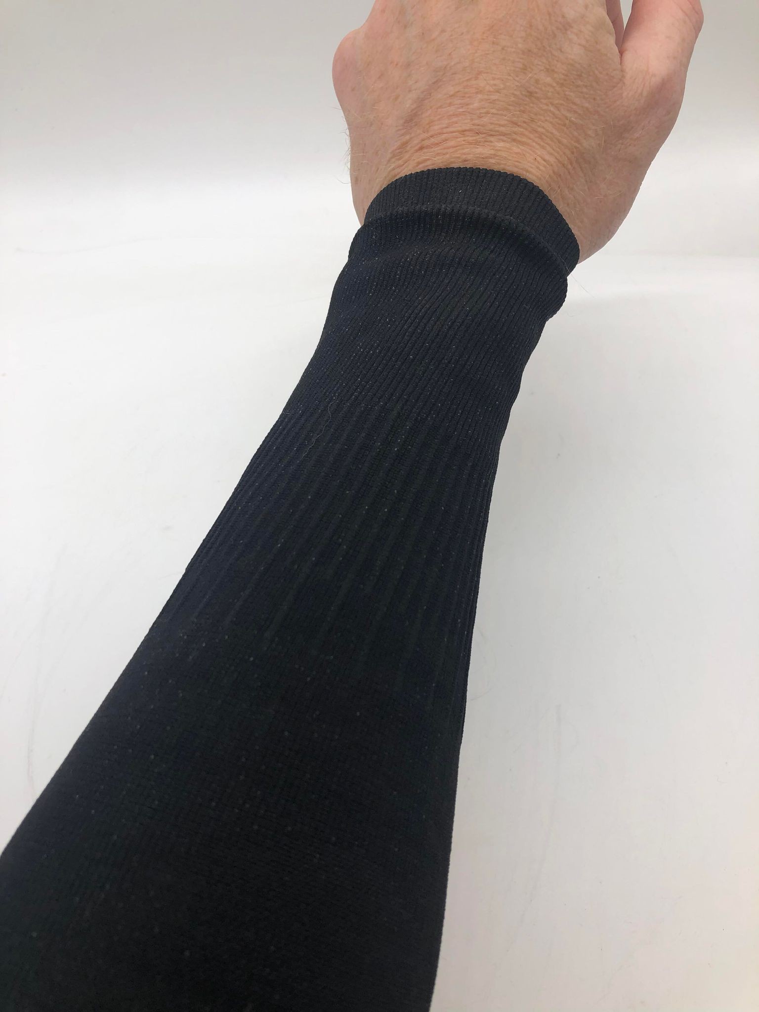
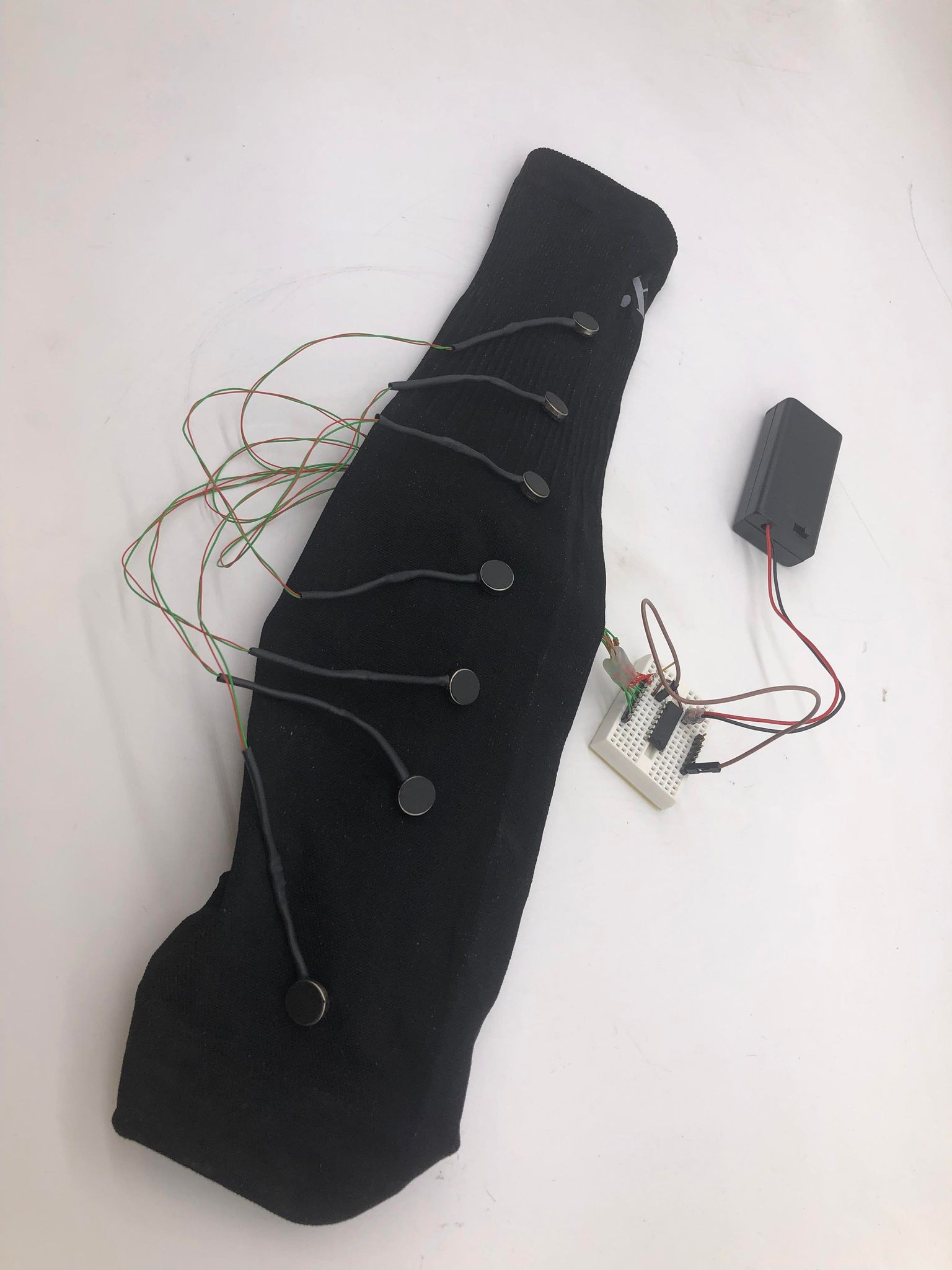
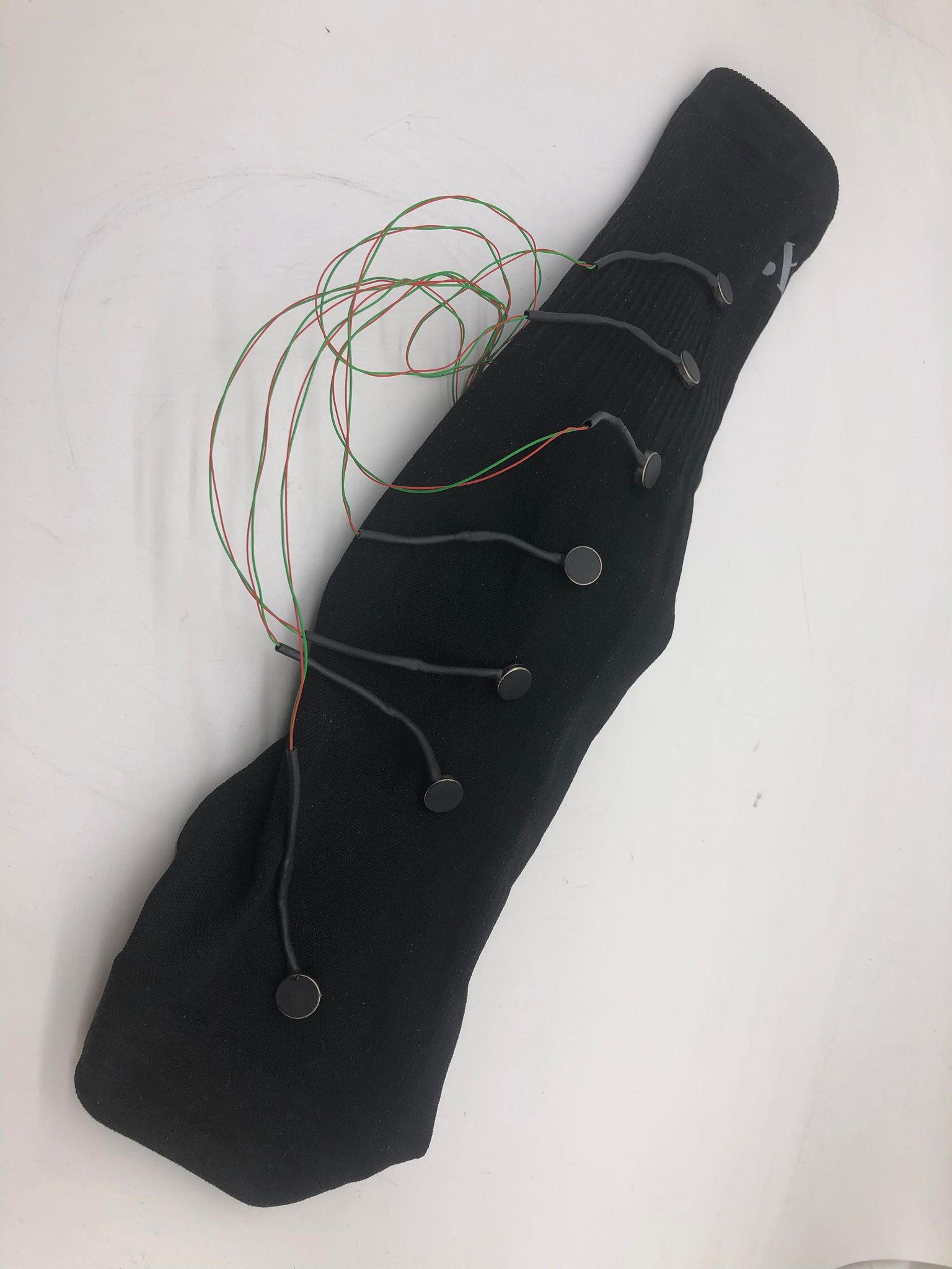
Designing the Sleeve
07/02/2022 at 01:46 • 0 commentsAs we bring this project together, it's time to assemble the components. We have breadboards, PCBs, motors, and battery packs (oh my). We have worked with several ideas, and this is the end result for a layout.
![]()
Wearing the sleeve is comfortable. It's a compression sleeve used by athletes, and those it is meant to take a lot of abuse (i.e., physical activity and sweat). It can be worn for an extended period of time without a sensation of being weighed down by a lot of equipment.
![]()
The battery pack and control board are attached to the back of the sleeve for ease of use.
-
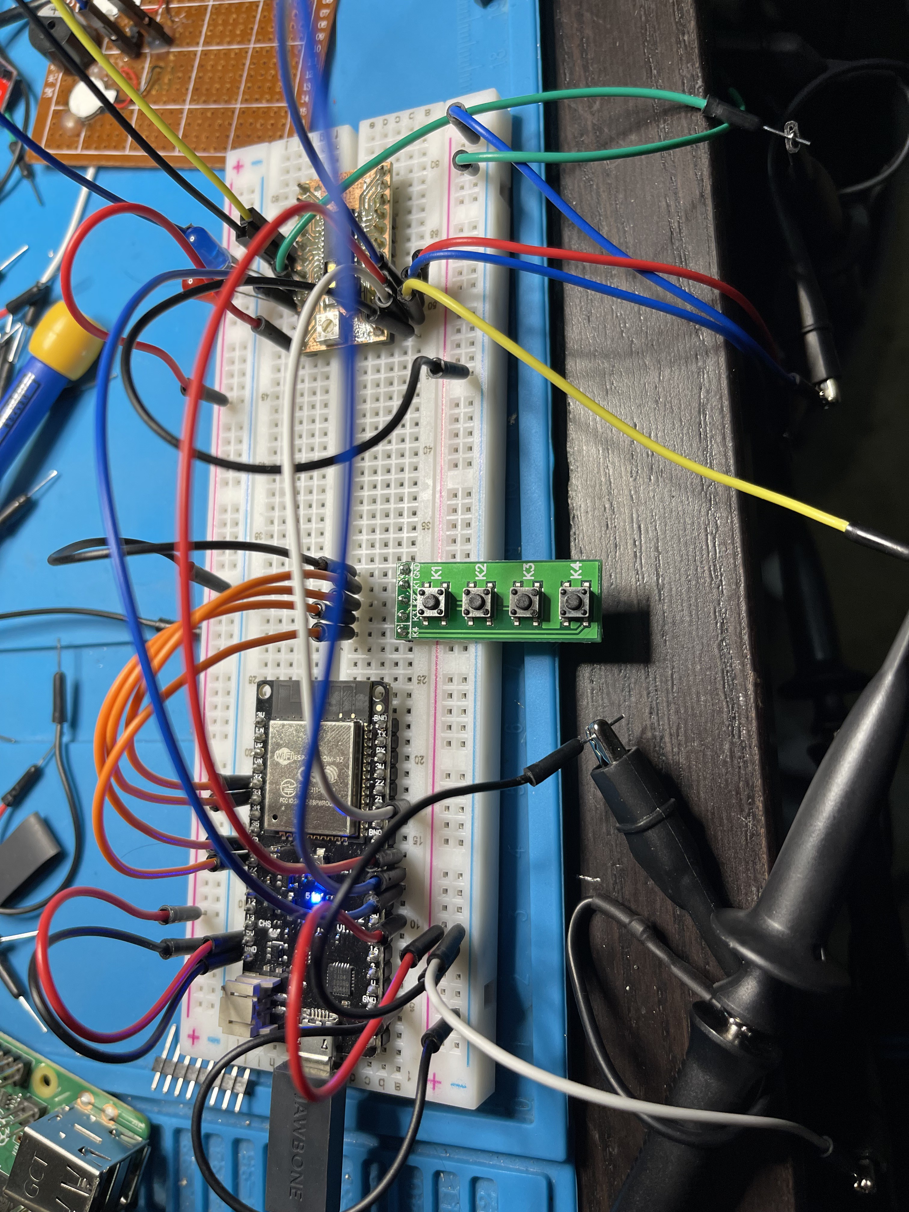
Prototype on a PCB
07/01/2022 at 17:58 • 0 commentsOne of the challenges we have as a team is handing around prototypes on breadboards. They work fine, until you drop one, a curious teen in the car plucks a wire out, you wire in a color spectrum chosen specifically to confuse your colorblind co-inventor. Now that we have a working driver system, we can create a PCB where we can pass around the hardware and play with software, haptic placements, product design and not worry too much about the wires.
The kind folks at PCBWay offered to sponsor us with some PCB Fabrication.
![]()
I sent in my design on a Sunday night, and I had the box in my hand Friday afternoon.
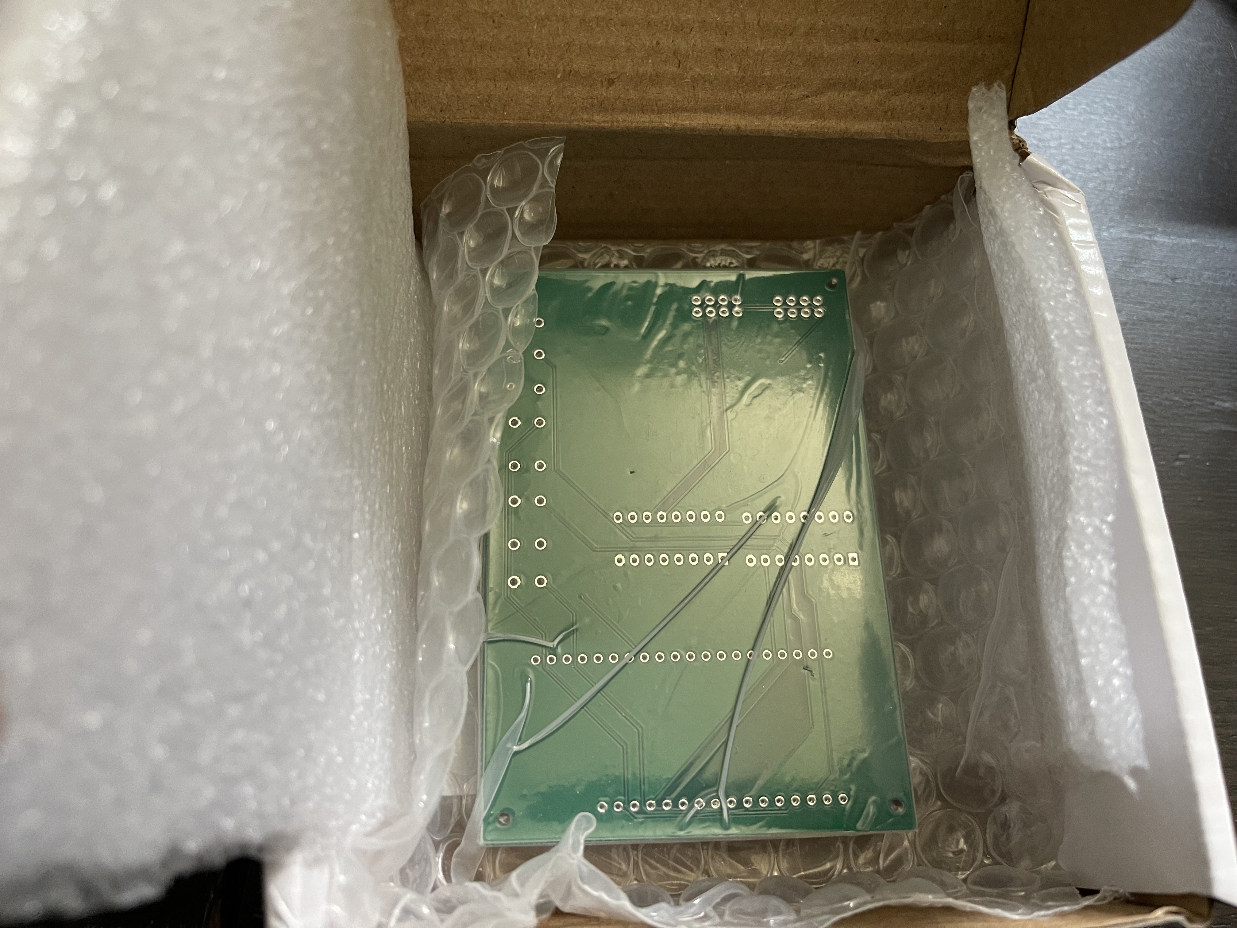
![]()
The outside of the box was a little squished, but the inside was properly packed and everything looked good.
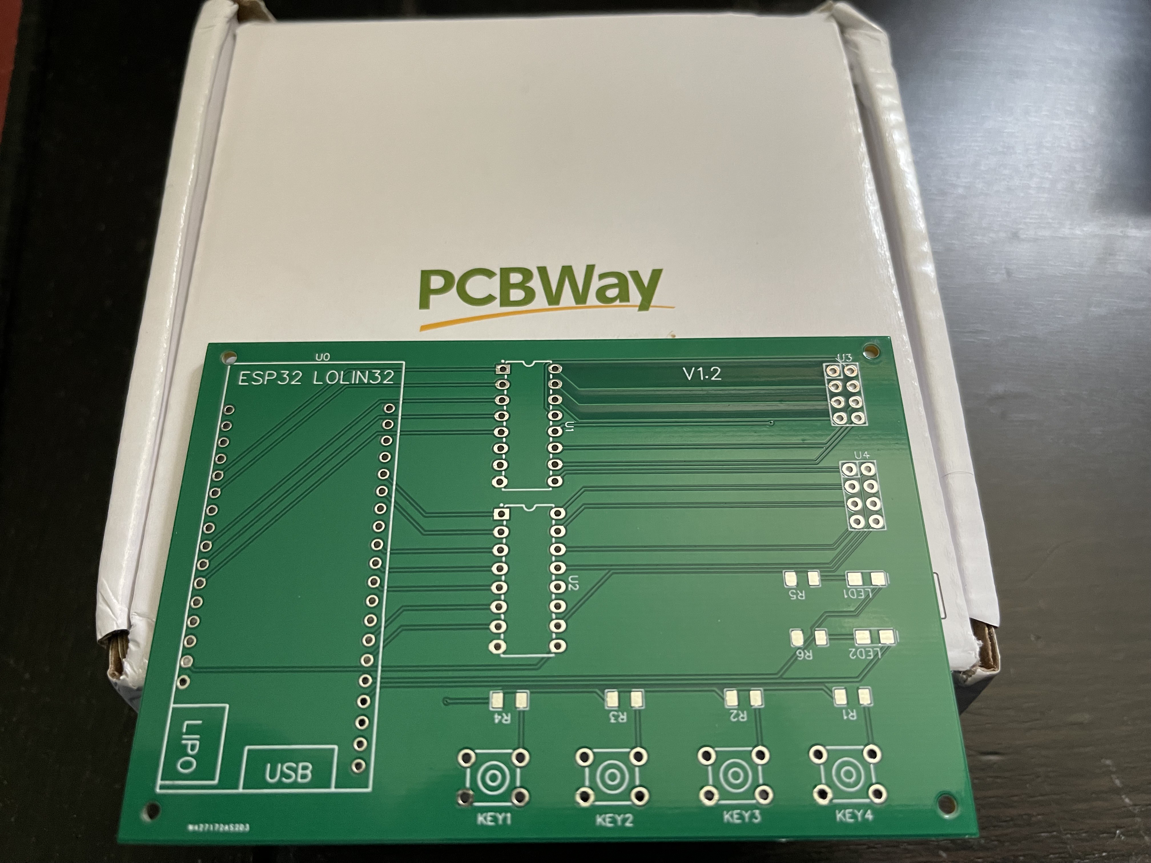
![]()
All 5 boards are flawless, traces look great, silk screens are bright and easy to read, coper and coatings are all uniform.
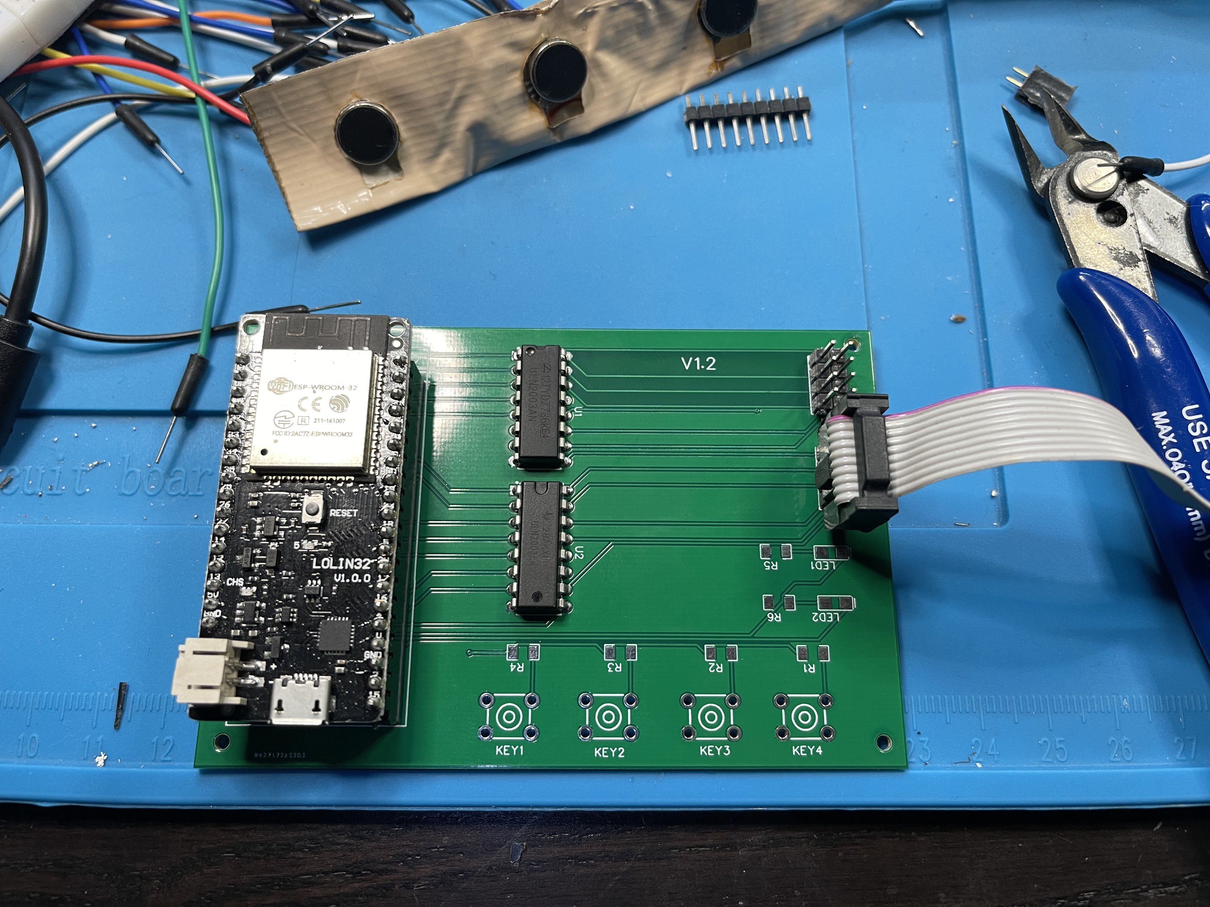
![]()
Moved from Breadboard to PCB successful, and everything works. I'll add the push buttons and LEDs later. Now I can get back to designing the software and getting feedback on the haptic feedback.
-
Experimental system
06/30/2022 at 15:16 • 0 commentsDrive problems
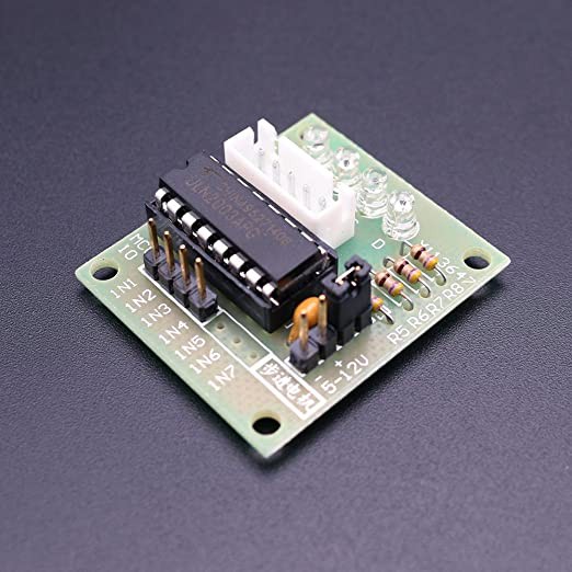
After discovering that LED drivers are not the right solution for driving motors, I noticed that stepper motor driver boards use a ULN2003 motor driver chip. These are available on eBay for thin money, and I had a few lying around.
![]()
The ULN2003 can drive 500mA across 7 outputs, which is about 70mA per line. That's in line with what the motors need, and with PWM and non-constant activation this should be a good solution.
Mounting problems
We've noticed that mounting the motors to duct tape - an easy, rapid prototype solution - doesn't work well due to the inherent stiffness of the tape. Any motor will vibrate a fair length of the tape, making it difficult for the user to distinguish one motor from another.
It's become clear that this project won't have a simple implementation, and we need to do some actual development and experimentation.
...which actually makes the project more interesting.
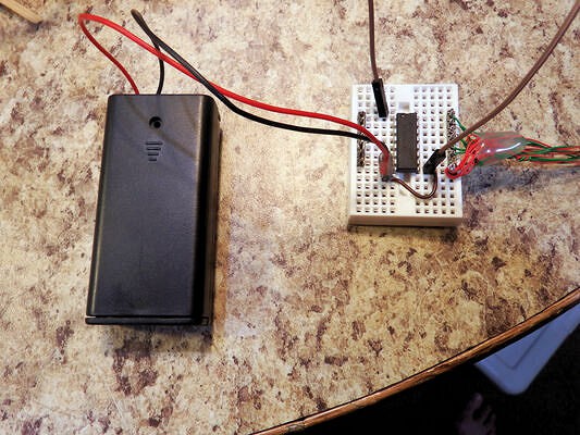
Dev kit for experimentation
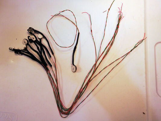
So I made up a dev kit of sorts, with 7 motors on 14" wire wrap leads, so that we can experiment with motor position, different mounting fabrics, and so on.
It's also battery operated, because of course you never want to connect something to your body that also plugs into the wall.
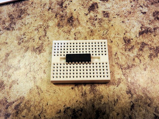
Start with a ULN2003 on a small blox breakout
![]()
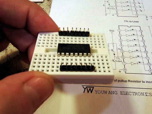
Add some headers left and right for the motors (bottom header) and control (top header)
![]()
Headers take wire wrap quite well. The common power lines are also pin 9 on the chip, so that works out well.
![]()
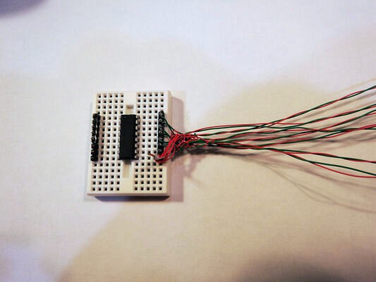
Add a big blob of hot glue to act as a strain relief. This will prevent (or at least, greatly reduce the chances of) the wires from breaking at the header interface.
![]()
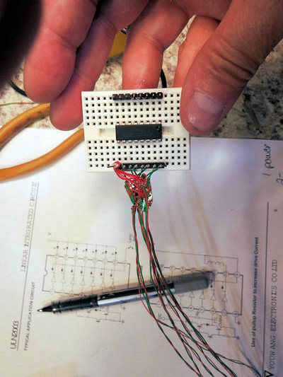
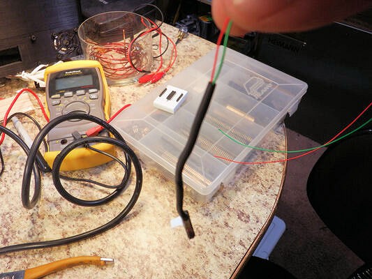
Add a 3 volt supply and activation lead.
To use, connect the activation lead (one end shown on the blox) from V+ to any of the 7 unconnected header pins on the left, and the corresponding motor will activate. Short out several pins to V+ to activate several motors at once.
![]()
-
Working with tiny wires
06/29/2022 at 18:57 • 0 commentsPrior Planning makes tedious jobs easier
Attaching 14" leads to 30 vibration motors using thin wires is a complete PITA, so I took some time to come up with a fast way.
It occurred to me that if one were to hook one wire on another with a weight at the end, the hooks would keep the wires in contact while soldering. The motors act as an acceptable weight, and the whole process becomes much simpler.
I was able to process 16 motors in in an hour using the following technique. Someone with younger eyes could probably do it a little faster - I always seem to have trouble "threading the needle" when hooking the motors.
You may be able to extend and adapt this system for even better results.
Tools needed
- Two sticks (pencils will work)
- Rubber bands
- Twist ties
- Heat shrink tubing
- Long rules
- Clamps
- Drill gun
- Wire wrap stripper
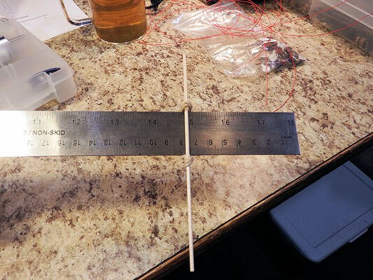
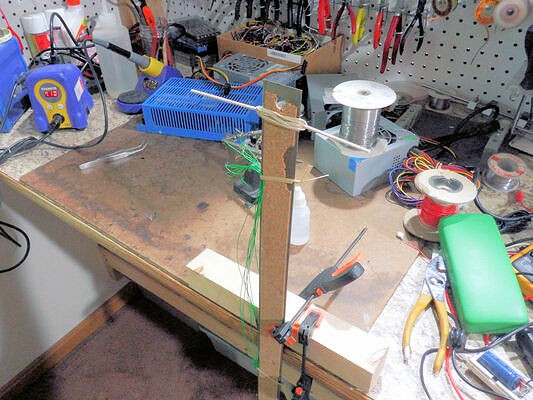
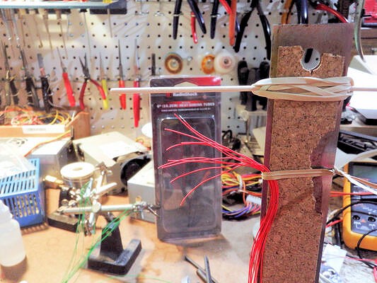
Step 1: Make a wire jig
The first step is to make a jig to allow fast measurements and cuts of wire. Some hobby sticks and rubber bands attached to a ruler fit the bill.
Here's a hobby stick fastened at the 15 inch mark:
![]()
And here's the other end, at the 1" mark. Total 14 inches of lead.
![]()
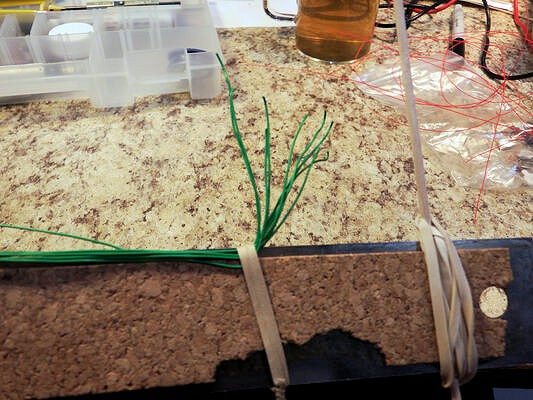
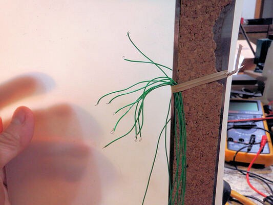
Wind the wire across the two jutting sticks
![]()
Using twist ties (the grey thing on the ruler), clamp the wires onto the ruler to keep them together. Use two or more ties - at least one at each end.
![]()
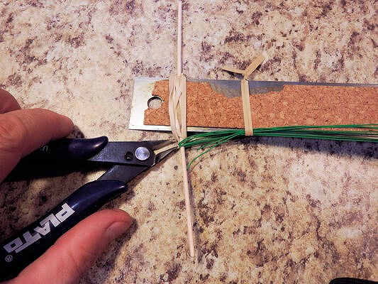
With the wires clamped, cut the wires loops at each end.
![]()
When done, bend the wires out so that they are held tidy by the twist ties. Bend the bottom section of wires (not shown) up 180 degrees and twist them together. This will help keep both ends in place.
Result: N wires neatly held to the rules, where N is the number of wire loops.
![]()
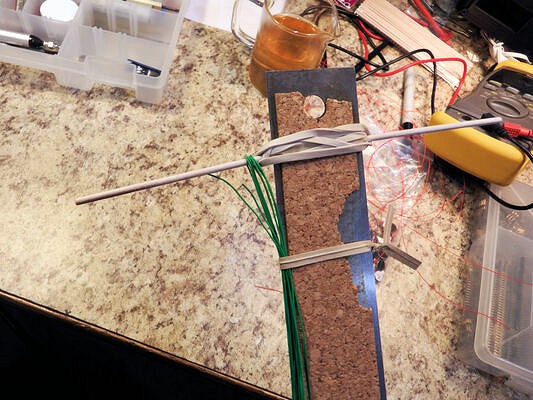
Step 2: Soldering the motors
Clamp the ruler+wires onto your workbench for soldering.
![]()
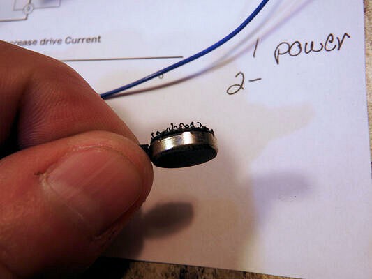
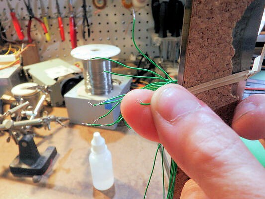
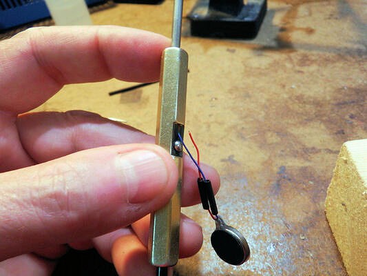
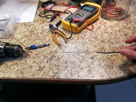
Strip the ends, and use a pair of tweezers to put a loop in the stripped end of each wire. (One loop shown against the finger.)
![]()
Loops in the ends of all wires.
![]()
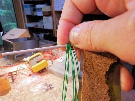
Place bits of heat-shrink tubing on the motor wires, and strip the ends if needed.
UPDATE: I've found that the existing tiny tinned ends of the motor wires are sufficient for this. A pair of tweezers can put a hook into the end of the wire sufficient for the next step, no extra stripping needed.
That being said, stripping back an extra 2mm won't hurt.
![]()
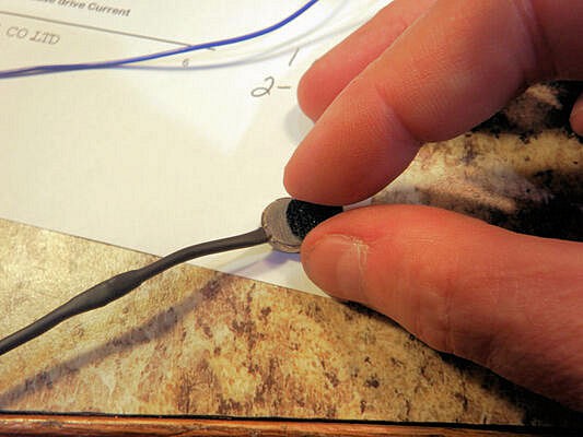
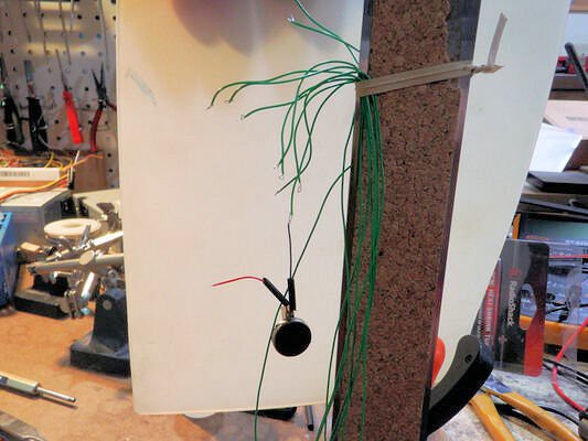
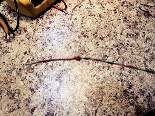
Using a pair of tweezers, make a "hook" in the end of the motor wire, and hang a motor on the end of one of the looped lead wires.
![]()
And solder. The weight of the motor and the hook-loop combination will keep the wires in good contact while soldering.
![]()
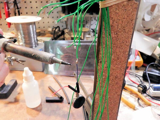
Repeat for the positive-side leads.
![]()
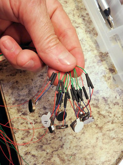
Step 3: Dressing
Gather the soldered motors and slide the heat-shrink tubing over the solder joints.
![]()
Hit all motors en-masse with a heat gun to set the heat-shrink.
![]()
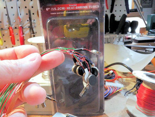
Add a longer, slightly bigger heat-shrink sleeve over the sleeved solder joints, all the way up to the motor connection. Slide the sleeve over the motor landing pad, where the leads connect to the physical motor.
![]()
Tie a knot in the wire ends, about 2" from the end.
![]()
Grab the knot with the jaws of a drill gun and put a few twists into the wires.
Don't overdo it - about 10 twists will suffice to keep the two leads together.
![]()
Result after about 10 twists.
![]()
Step 4: [Optional] Adding velcro
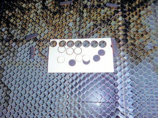
Cut out some velcro dots using the laser cutter. You can purchase velcro dots in various sizes, but I had velcro in stock and when you have a laser cutter, everything looks cuttable.
Also, I can make velcro dots in the exact size needed, the velcro doesn't overhang the edge of the motor and so doesn't tend to be peeled off as easily.
![]()
Remove the paper backing form the existing motor adhesive
![]() Remove backing from velcro and place over motor.
Remove backing from velcro and place over motor.![]()
Result: one motor, with velcro hooks.
![]()
All motors done.
![]()
-
Driving motors with LED drivers
06/29/2022 at 17:27 • 0 commentsA good idea that doesn't work
Two of my favorite phrases nowadays are "correct, but not complete", and "a good idea that doesn't work".
Using the internet and the hackaday search box, I found that you can use LED drivers to drive pager motors. I have a couple of LED driver chips lying around (16 LEDs each), they are good for 5 to 120 mA per channel, constant current set by an external resistor, and I've got one on a breakout board already.
Rapid development, good idea, right?
Problem is, it doesn't work. At least, it doesn't work very well.
We don't know what the actual problem is with the LED driver, but sometimes the motor stalls and the leads have to be swapped, the response is sluggish, and a host of other feel-type problems make this not a good solution.
Motor PWM frequency
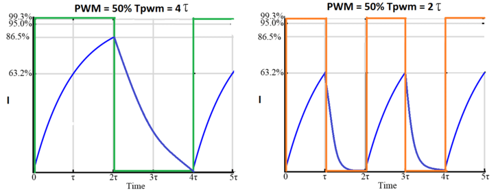
One issue with the LED drivers might be PWM frequency. The LED drivers allow individual current/brightness setting over and above the base current. This is most likely done with a PWM signal that determines the average current. That can be a problem for motors.
![]()
Source: PrecisionMicrodrives.com As shown in the image, the motor is essentially an inductor, and will have an exponential rise in current when turned on. The magnetic field builds, causing a back EMF that opposes the incoming current, until peak current is reached.
When the PWM frequency is shorter than the time constant of the coil, the result is much less current given to the motor. This can result in sluggish behaviour and low apparent power.
Error detection
Another possible problem is that the LED drivers have built-in short and open detection. I don't know what the chip actually does when it discovers a shorted LED, but that's probably the root cause of the motors stalling. When we unplug the motor and reverse the leads, this probably removes the short condition and the chip reverts to normal.
Constant Current or Voltage?
Another potential issue is that the LED driver is driving a constant current load, which is appropriate for devices that have a constant voltage, such as LEDs. A motor, once the back-emf has risen, looks like a constant resistance and so should be driven by a constant *voltage*, not a constant *current*.
A constant current driver will adjust the voltage to enforce a specific current, which means that it might use a potentially huge voltage at the outset and then reduce the voltage as the device ramps up.
This is probably the root cause of the motor sluggish behaviour and problems with the general feel of the tactile sensation.
Summary: Don't use LED drivers
So in summary: LED drivers may seem to be a good solution, but are probably not optimal. There are actual motor driver chips, such as the ULN2003 that we are currently using, that are a better match for driving pager motors. These also have kickback diodes onboard, so the final circuit requires fewer components.
-
Getting My First Sleeve Done
06/26/2022 at 23:01 • 0 commentsI have been going through a couple different iterations of how to mount the haptic sensor and create a comfortable wearable.
Our first efforts used a folded piece of gaffer's tape (similar to duct tape with a more flexible feel). This worked but the sensors were too close together and made it challenging to discern the level that the sensor was at.
Now we have a compression sleeve for the haptic sensor to be mounted on. We are also changing from a single string of sensors to individual motors that will attach to the sleeve via hook & loop fasteners. Only the hook side of the fastener will be used to latch into the sleeve, and this will allow for isolation of the buzzing from the individual motors for the haptic sensor. Our concern was that some of the vibration was being transmitted across the connected medium (i.e. the tape).
After considering the sleeve, I think I might like to see an LED on top of each motor so that a visual que is available as well; however, I want to be cautious with this and not create scope creep for the first generation of this effort.
![]()
-
Prototype Take 2
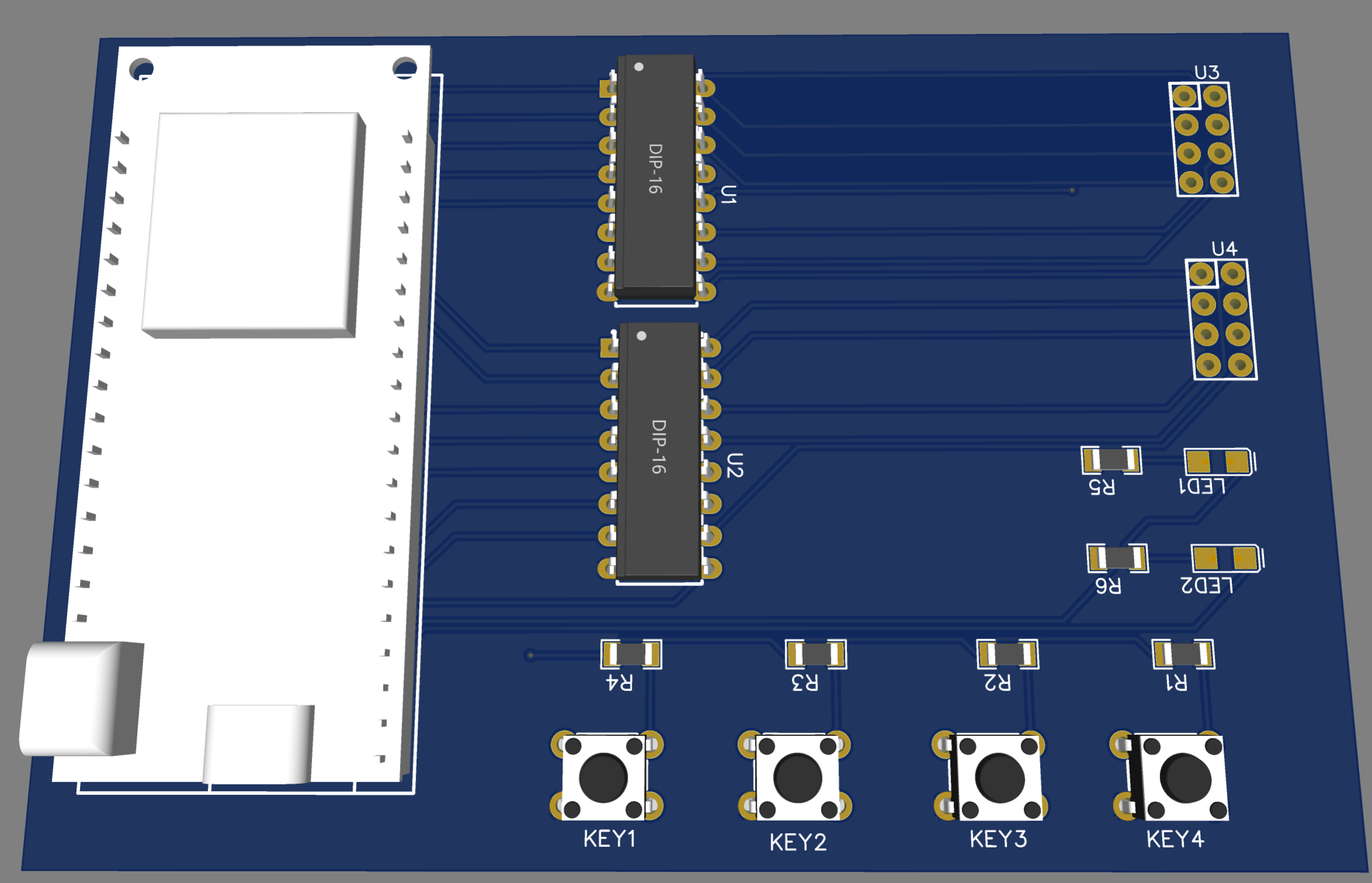
06/25/2022 at 01:38 • 0 commentsGiven the success of using the ULN2003 circuit I designed a new version of the breakout board. Using two driver chips vs. my previous create my own 12 channel driver with discrete components is much easer, who would have thought.
![]()
I'm going to send this off to be fabricated, PCBWay has offered to sponsor our project with some PCB manufacturing, which is great!
-
Oh my Darling(ton)
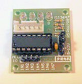
06/25/2022 at 00:13 • 0 commentsAfter the lack of success using constant current drivers, we continued to search for a driver that would be cost effective, off the shelf and easy to implement. The UNL2003AN is a common driver circuit used in small stepper motor drivers.
![]()
We won't need the entire circuit, but the ULN2003 circuit, which is a Darlington Transistor Array: ULN200x, ULQ200x High-Voltage, High-Current Darlington Transistor Arrays datasheet (Rev. P) (ti.com)
Wiring this up to my prototype rig and it really works. It is simpler and more responsive than my initial level shifter rig, and adds the driver protections I need to protect the controller. So far so good. I'll continue to build out and test with this circuit and see how everything works.
-
Keeping the Drivers Constant (Current)
06/23/2022 at 05:00 • 0 commentsWe wanted to take a look at a novel approach to driving the haptic motors. Why not go for a common and cost effective constant current driver? Teammate Peter provided a driver for me to play with. It is at this point I started to wonder if he is playing with my mind. The driver provided is a SM16126D, for which I can I only find the specification sheet in Chinese 1804162143_Shenzhen-Sunmoon-Micro-SM16126D_C81394.pdf (lcsc.com). Well, CLK is clock in any language, let's wire this up.
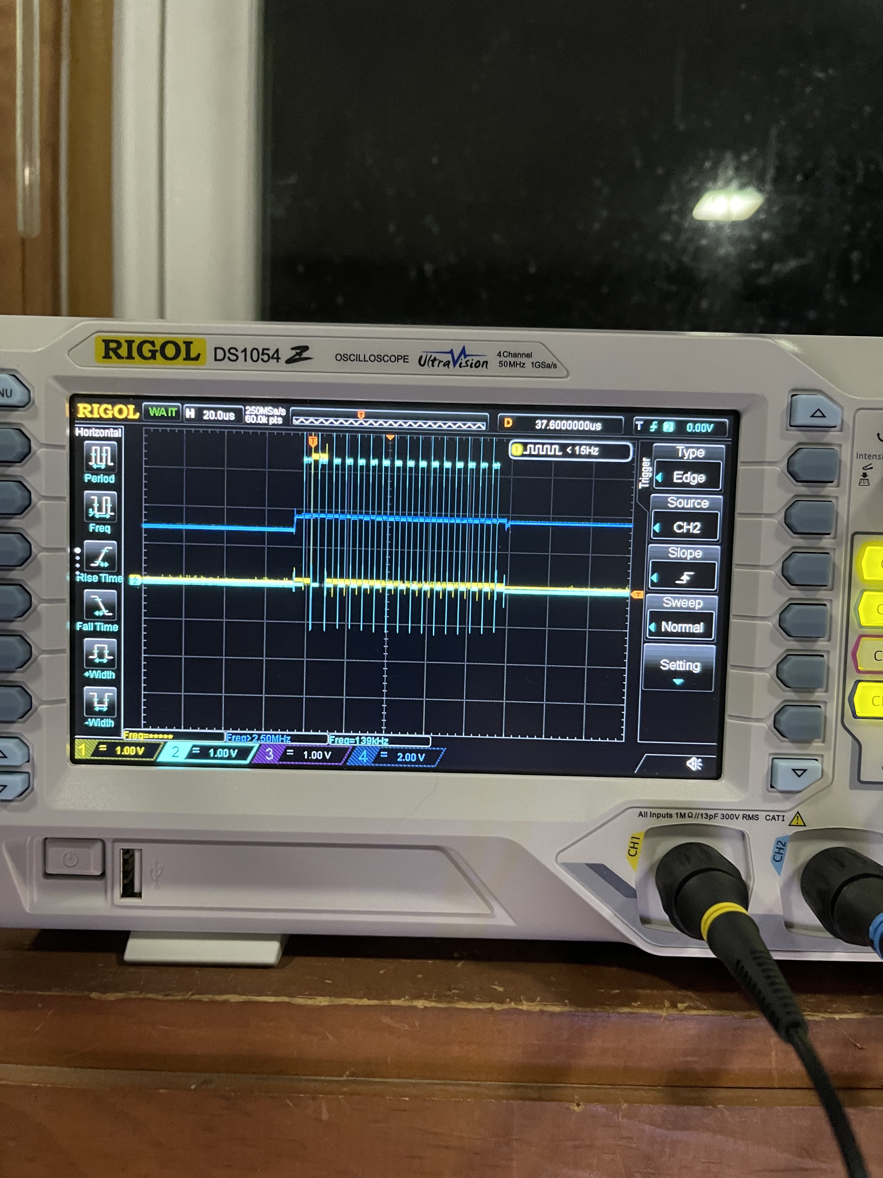
Not wanting to get too crazy, I went with timing using the Arduino delayMicroseconds with the minimum recommend value of 3. That gives me a clock frequency of 333Khz which is well below the max frequency of 25Mhz that the chip can handle, yet it should give me some level of control over the sensation provided by the haptic motor.
![]()
Breadboard that all up with the circuit.
![]()
Nothing good... unfortunately the motors in the haptic device don't appear to respond well to the constant current driver. The motor will spin up a few times, then not work again unless I reverse the polarity, then I get a few more spins. I think it may have something to do with how the constant current driver is always at a specific voltage and limits the current to zero when in an "off" state. You can see it as the Blue trace on the scope.
A few more tests, but I think I may be back to the driver drawing board, and off to a more traditional motor driver configuration.
-
Seven, plus or minus two
06/17/2022 at 14:24 • 0 commentsRaindrops
The project team has been experimenting with combinations of number of motors, vibration intensity, pulse timing, and so on.One interesting result is that when motors are given a sudden start and random decay (across all 6 motors), the effect feels like raindrops.
Interesting.
Despite this, sensory measurement seems difficult to achieve: each motor vibrates a section of the tape (holding the motors), in such a way that it's difficult to distinguish one motor from another.
My next task is to see if there's a way to mechanically isolate the motors, so that their buzzing doesn't vibrate more than the motor itself.
Seven, Plus or Minus Two
In the highly cited paper "The Magical Number Seven, Plus or Minus Two", it is revealed that the channel capacity for distinguishing stimuli is roughly 7 in any dimension.
From that paper, I found the following:
![]()
The whole paper is an easy read and highly interesting, well worth the time.


 Remove backing from velcro and place over motor.