-
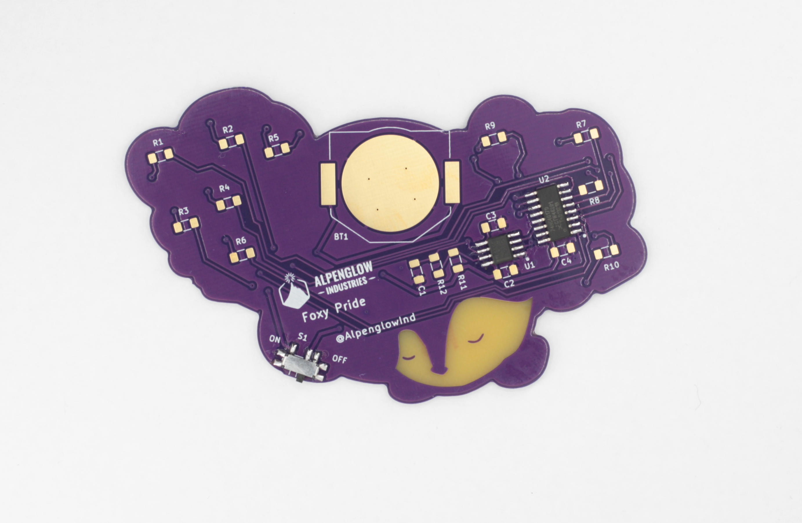
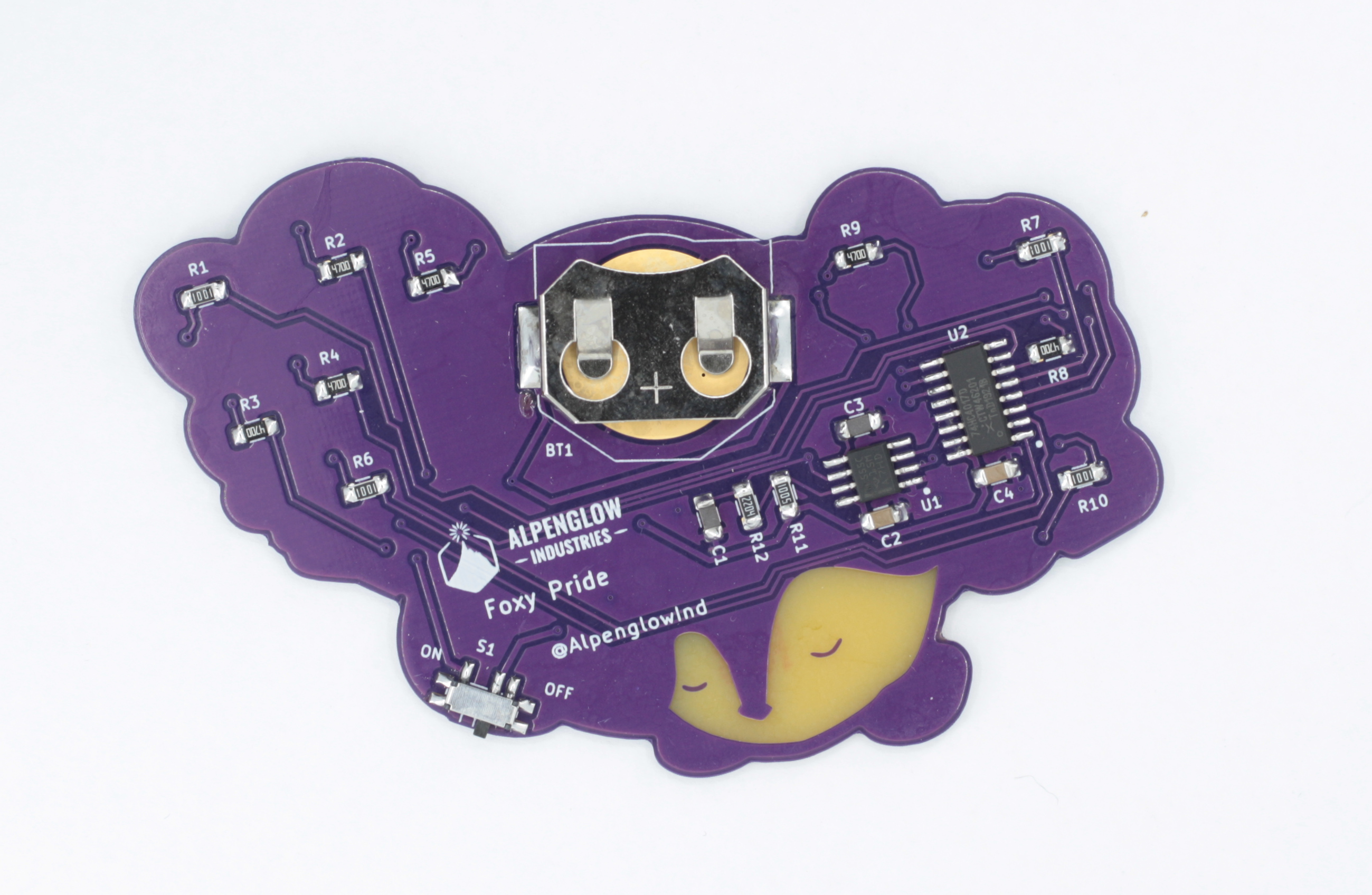
1Step 1: Solder switch, 555 timer, and decade counter
I tend to start with components that have the most legs. I find it easier to solder them when the rest of the board is clear.
*Remember the 555 timer and the decade counter are both directional so be sure to match the line on the chip to the line on the footprint
![]()
-
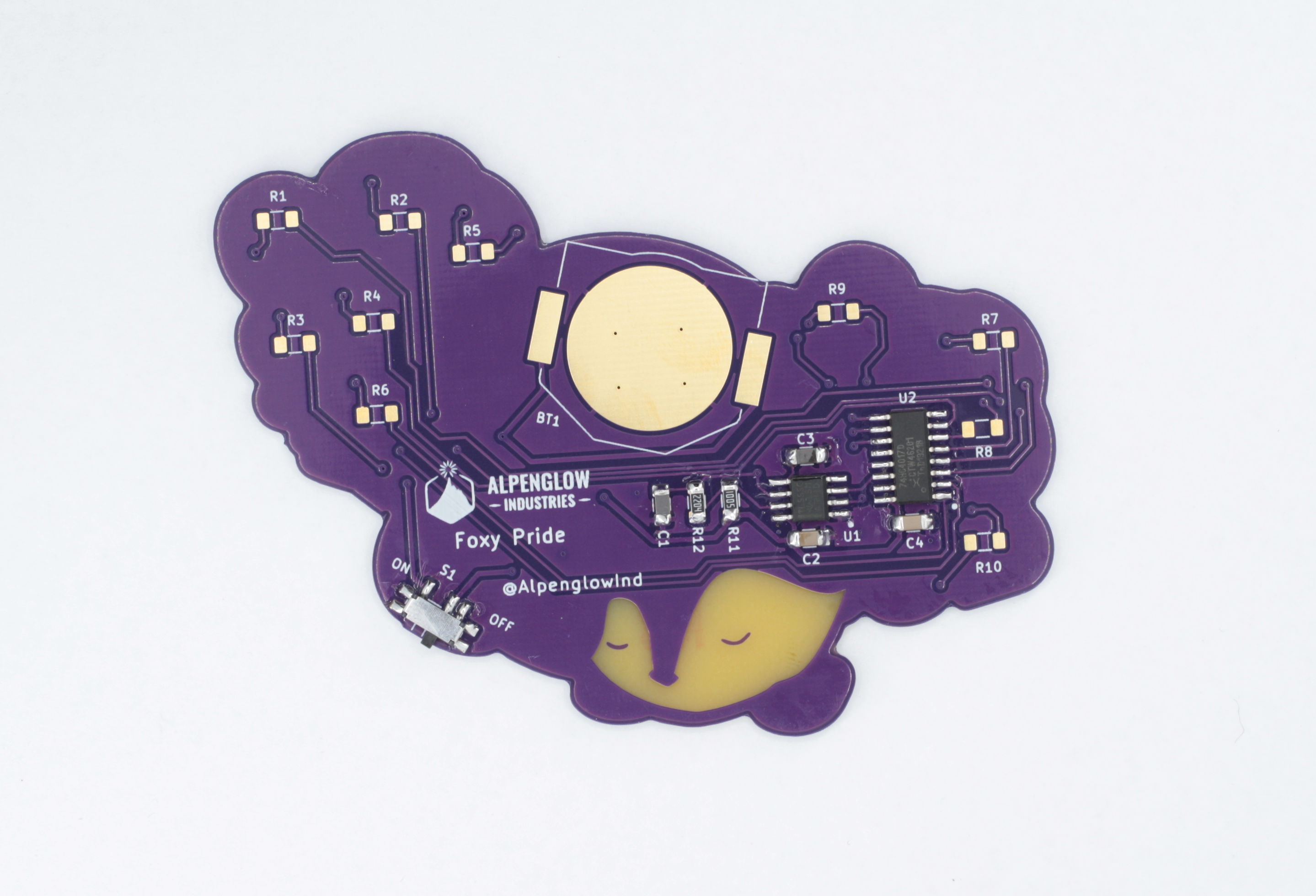
2Step 2: Resistors R11, R12
![]()
-
3Step 3: Capacitors C1-C4
![]()
-
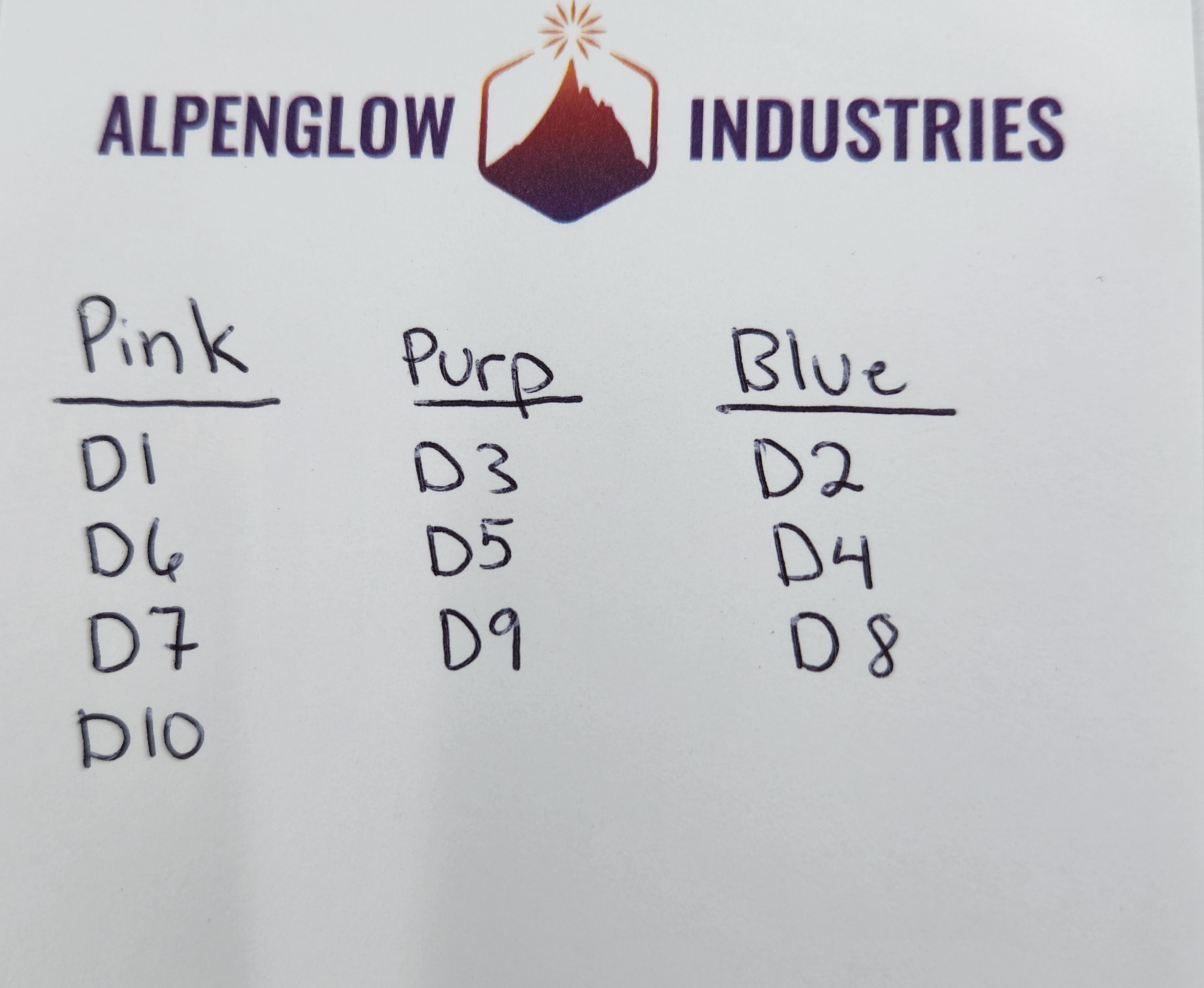
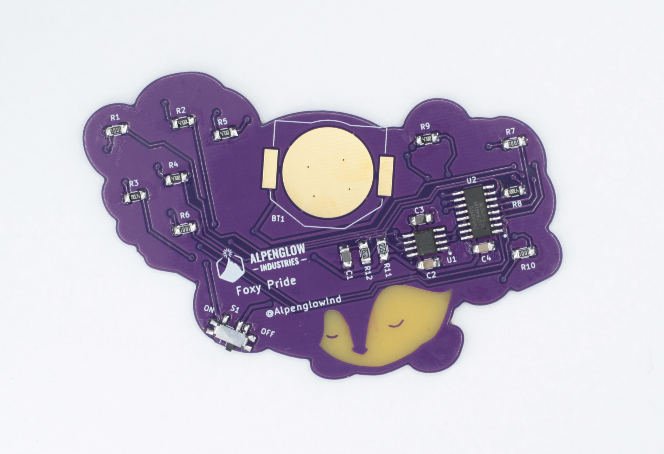
4Step 4: Pick LED colors you want on front, note reference designators and solder corresponding resistors to back
I wrote down which color LEDs I wanted to go where. Reference numbers match on the front and back so D1 would go to R1 and so on.
![]()
![]()
-
5Step 5: Solder LEDs
*Make sure your LEDs are going in the right direction. Match the green dot on the LED to the line on the footprint.
![]()
-
6Step 6: Solder battery holder
*Note: The battery holder is made of metal so it gets hot when soldering. I suggest using a silicone finger protector to hold down the battery holder while soldering it into place. Be careful touching it during and directly after soldering!
![]()
-
7Step 7: Add batteries and turn on!
![]()
Foxy Pride Badge
Show your pride with the Foxy Pride badge with artwork designed by Leeborg_
 Alpenglow Industries



Discussions
Become a Hackaday.io Member
Create an account to leave a comment. Already have an account? Log In.