 kmatch98
- I’m starting to plan for a development board for this touchscreen display, since there is a giant mess of wires on my current breadboard. I want this board to mount to the back of the display and provide the FPC connections to the Display and Touchcscreen and provide the current limit control for the white LED backlight. Optional features include a battery charging circuit I think that won’t make it on the first revision
Here is a list of items I want to include:
- ESP32-S3 demo board (2 x 22 0.1” header pins)
- Solderable header pin breakout connections
- Adafruit Feather header connections (Optional)
- 40 pin 0.5mm FPC connect for LCD display
- Breakout for all 40 display pins (Optional)
- 6 pin 1.0 mm FPC connector for touch panel
- Breakout for 6 touch panel pins (Required)
- Backlight driver circuit with PWM control
- Backlight connector - I think this is Molex Picoblade, 2 pin
- Backlight connector - solderable header pads
- Battery charger circuit (optional)
- Battery connector (optional)
- LiPo battery (optional)
- Header connections for unused pins (combine with above)
- Stemma QT connector for I2C (optional)
- Mounting holes
Details, details
03/06/2022 at 00:40 • 0 commentsI suspect the old adage of “measure twice, cut once” is applicable for PCB design so I’m going through step by step with the pin outs for the ESP32-S3 DevKit and the LCD panel.
I verified the touch panel on the TSS-752 matches that of the other mode I tore down, with
- GND
- 3.3v
- SDA (GPIO42)
- SCL (GPIO41)
- Interrupt (GPIO40)
- Wake
I connected as shown to the GPIO pins listed above and it works with the CircuitPython FocalTouch library from Adafruit.
Also, I’d like to include the backlight control circuit on this board, so I tested Adafruit’s TFT friend. In testing I didn’t realize it had breakout pins for the backlight and in the process almost burned up the board. Lucky the display driver has overtemperature protection! Anyway, I verified the circuit is working for my backlight. Yet I still need to finalize the desired maximum current and also want to try out the PWM control for brightness. Unfortunately that specific chip used on the TFT Friend is unavailable. However, this chip from OnSemi looks similar: CAT4139TD-GT3. Need to verify the recommended inductor and diode footprints though.
Still a lot of details to sort out but it’s coming together. One more concept I’m exploring is some pluggable Stemma QT ports for sensors. But unfortunately there are no PCB mountable sockets that can plug into the sensor boards. Maybe I can hack it together by using a cable and a 3D printed case and epoxy.
Making life easier (maybe) with a Circuit Board
03/09/2022 at 22:31 • 0 commentsThis display looks well-hackable as long as you have a dot-clock controller. Now with the ESP32-S3 DevKit board that can use the internal LCD peripheral to drive dot-clock displays, I need a good way of connecting one to my board for testing and for further evaluating if CircuitPython can be cajoled into running this touchscreen display.
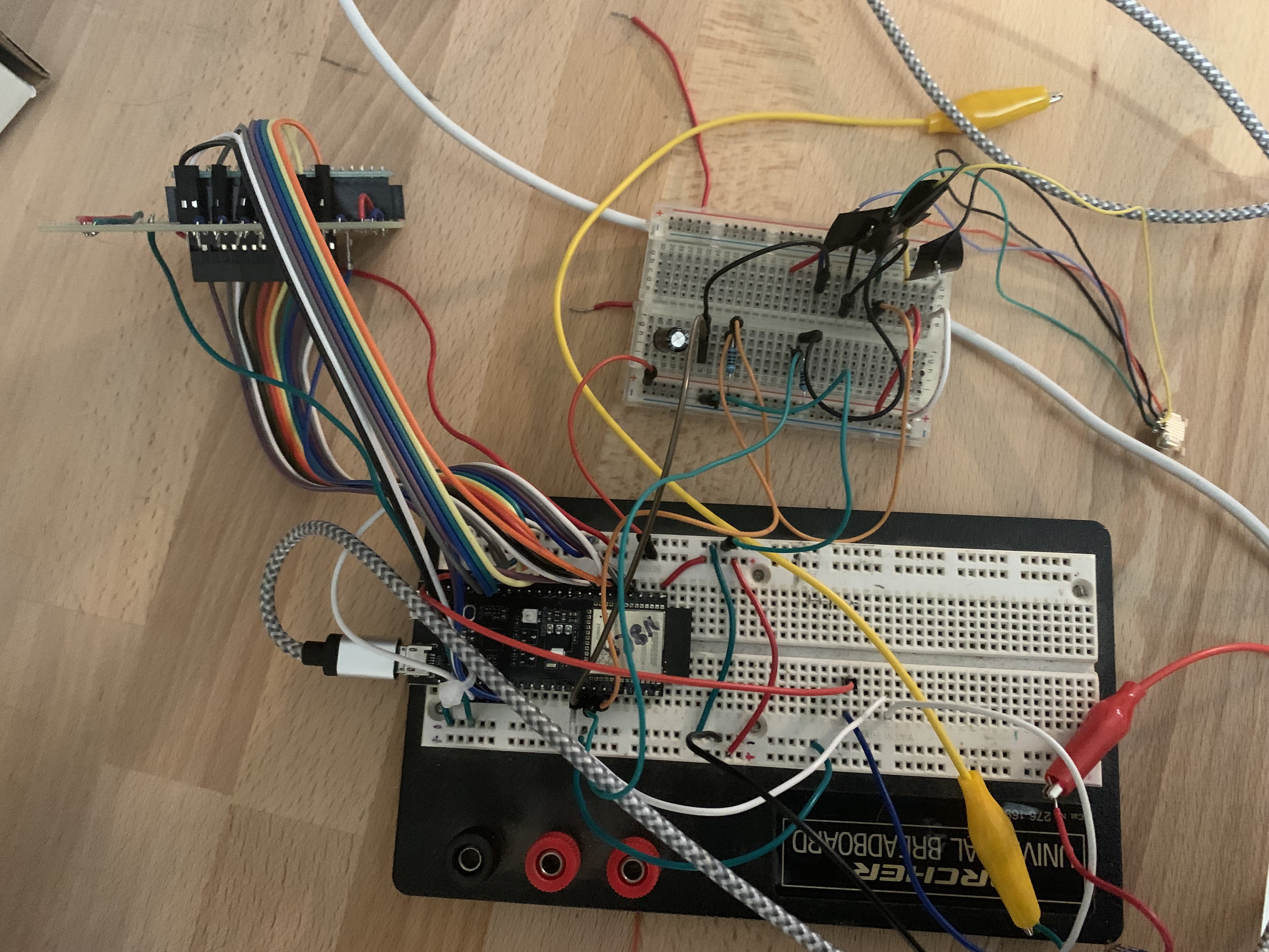
To first test the ESP32-S3 DevKit board, I ran the lcd_rgb demo code along with a giant mess of wires using Adafruit's 40-pin FPC-to-header connector and a 40-pin (2x20) header breakout. I tried my best to use these header pin connectors, but whenever I attach the display, I tend to pull out a few wires.
![]()
So, with all this risky display wiring, it's now time to bite the bullet and learn how to make a PCB. This will reduce a lot of frustration of removing wires and add the frustration of learning KiCad and how to order SMT PCBs for service and how to bogde any layout errors.
Here are the goals for my design:
- Make it easy to attach the display firmly to the ESP32-S3.
- Try out a couple of circuits: backlight controller and battery charger
To test out the current required for the backlight, I first used a bench power supply and my DMM. Somewhere around 100mA looks about right, and that occurs around 10V. I then procured the TFT friend from Adafruit and tested it out. In the process of testing, I didn't realize that the backlight Anode and Cathode were actually broken out to a pin, I assumed they were solely connected to the 40-pin breakout. In the process, I ended up maxing out the backlight driver up to maybe 1 Amp and the inductor gets HOT HOT! I suspect the driver chip has a overtemperature sensor, since it rhythmically cut in and out until I realized what was happening. Anyway, I rewired properly and verified that 100mA was adequate for the display. Also, I verified PWM operation of the backlight controller brightness. Works great. I was amazed that the ESP32-S3 PWMio worked fine, even at this early stage of CircuitPython development.
Key parts for my circuit:
- ESP32-S3 DevKit connected by headers
- Additional solderable via holes in case I need to:
- rewire the microcontroller pinouts
- adjust backlight current
- modify the battery charging current
- change polarity of the battery or backlight connections
- 40-pin FPC connector (0.5mm pitch) for RBG display
- 6-pin FPC connector (1.0mm pitch) for touch panel controller - Note metal is on opposite sides on the two FPC connectors
- Mounting holes to display backside
- Backlight driver (100mA)
- Battery charger (stretch goal)
- STEMMA QT connectors (2) - 3.3V compliant only
- Battery power switch
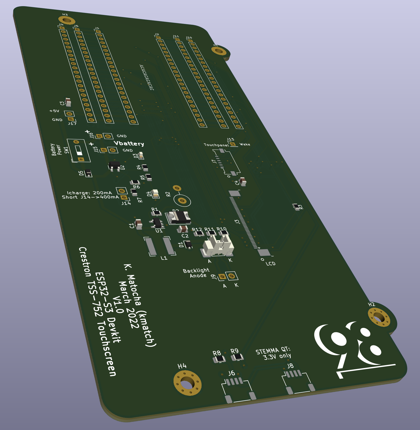
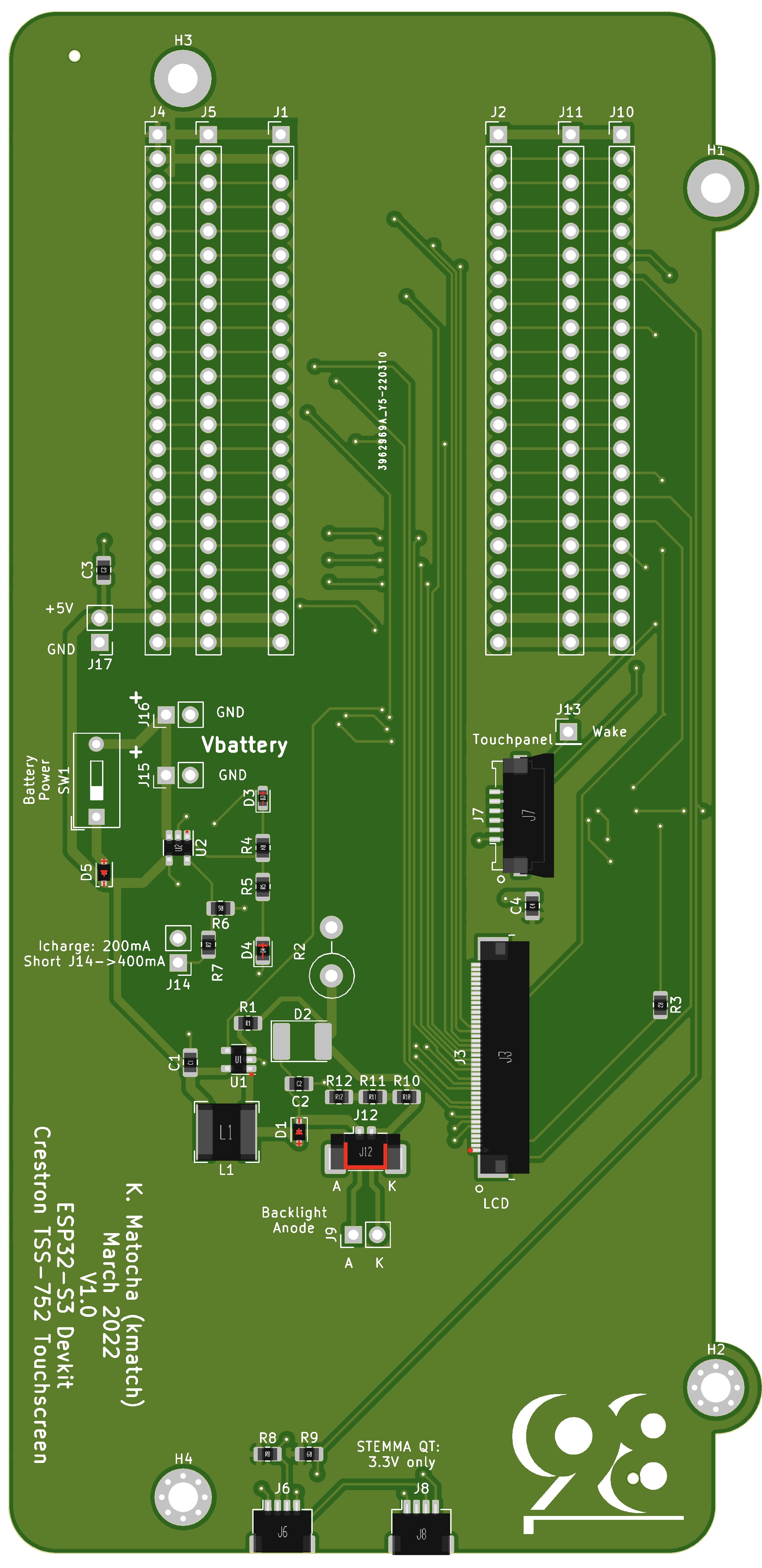
I made my first design in KiCad and will make an order. Fingers crossed.
![]()
![]()
PCB Planning
A project log for HACKtablet: Crestron TSS-752 Teardown + Rebuild
Tearing down a Crestron display conference room controller, the second. And making it into a CircuitPython device.
Discussions
Become a Hackaday.io Member
Create an account to leave a comment. Already have an account? Log In.