kmatch98
-
HACKtablet giveaway
07/26/2022 at 21:49 • 0 commentsThanks to foamyguy for organizing a giveaway of 5 HACKtablets.
Special thanks to Adafruit for supporting shipping costs. -
Cost of prototyping
07/26/2022 at 13:27 • 0 commentsOne question you might have is how much will it cost to make a prototype like this.
Here is a rough set of expenses. Note that some things, like buying PCBs practically requires that you buy several, so it’s cheaper on a unit basis to buy and build several.
Crestron TSS-752 panels (used) - I bought a total of 10 of these. Unit cost was between 17.50 (for a pack of 5 on eBay) and 20, delivered. Rough total of $200, let’s call it $20 per panel
![]()
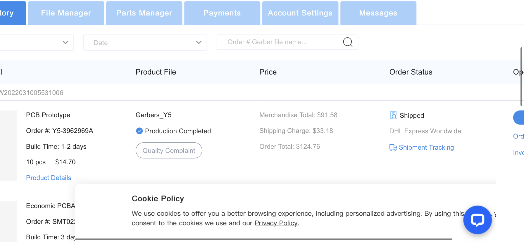
PCB, components and assembly service - 124.76 for 10 assembled boards, so $12.74 per finished board, delivered.
Esp32-S3 DevKit N8R8 - purchased from Adafruit with 20% off discount code but plus shipping, let’s say $20 per board delivered. I see these a bit cheaper for $15 at Mouser.
estimated unit HACKtablet cost: 20+13+20=$53 per HACKtablet
other development costs:I bought a couple other Crestron tablets of a different model: $80
USB cables: $20
Some adapter boards I used to connect the 40-pin FPC connector to a breadboard, and a display backlight driver helper board: $30
Overall this project has cost me around $600-700 and has enough materials to make 10 HACKtablet units. As for the number of hours, I’d venture a guess of somewhere around 200+ hours. If you calculate hobby costs, that’s $3/hr of entertainment. -
Updated Case with Port Cutouts
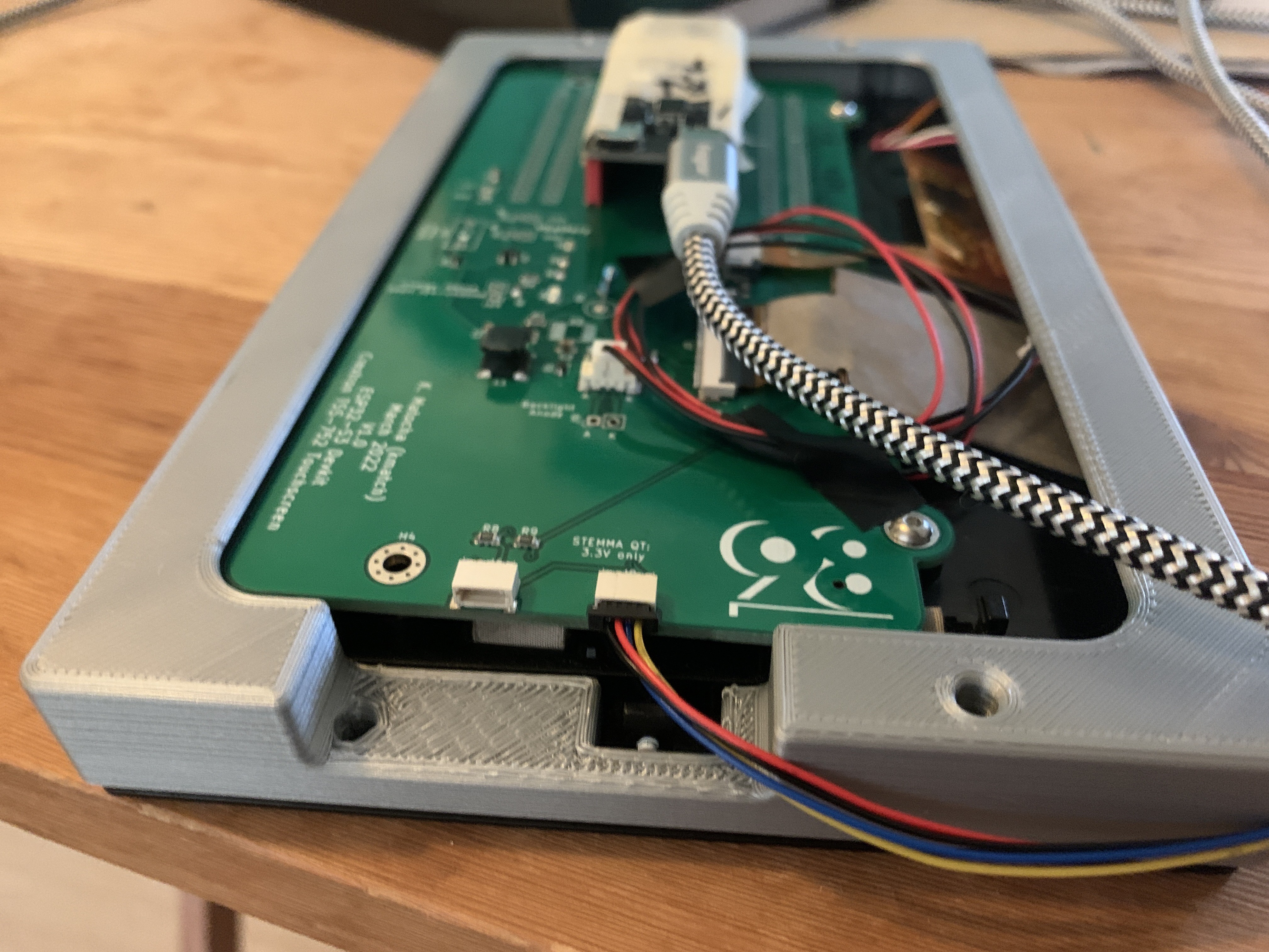
07/21/2022 at 13:33 • 0 commentsThe first case that I created obstructed access to the two Stemma QT ports. I’ve modified the case to accommodate access to these ports. Now the case requires some support, but seems to work. Note: My slicer also added support into the small clip "notch" holes, but it was easily broken out with a screwdriver.
The updated CAD files (Fusion3D, STEP and STL) are now located in the files section and are labeled "Stemma port cutout".
![]()
-
Video footage
07/21/2022 at 04:24 • 0 commentsHere’s some action footage of multitouch on the HACKtablet:
#t=17m18s
-
A video of building custom CircuitPython for the tablet
07/17/2022 at 16:12 • 0 commentsfoamyguy streamed two videos where he was able to successfully able to build and flash CircuitPython on the tablet prototype
There were a few misdirections in the streams but he got it to build.
Still several things to overcome to get it merged into Main CircuitPython but this is a good time next step:
-
Building CircuitPython for the HACKtablet
07/16/2022 at 20:24 • 0 commentshere are the rough steps for building CircuitPython for the ESP32-S3 N8R8 devkit board:
git clone git@github.com:kmatch98/circuitpython.git
cd circuitpyton
git checkout esp32s3_dotclockdisplay
make fetch-submodules
# Also I had to do this, I’m not sure which step.
git submodule update --init --recursive
cd ports/espressif
# Note: When I get here, the esp-idf directory is created, but empty.
git clone git@github.com:kmatch98/esp-idf.git
git checkout rgb_add
cd ports/espressif/esp-idf
. ./export.sh
cd .. # move up to ports/espressif folder
make BOARD=espressif_esp32s3_devkitc_1_n8r8
I got this error:
ninja: Entering directory `build-espressif_esp32s3_devkitc_1_n8r8/esp-idf'
ninja: error: '../../esp-idf/components/esp_lcd/linker.lf', needed by 'esp-idf/esp_system/ld/sections.ld', missing and no known rule to make it
# So I had to copy over this linker.lf file from the repo to circuitpython/ports/espressif/esp-idf/components/esp_lcd:
[mapping:esp_lcd]
archive: libesp_lcd.a
entries:
if LCD_RGB_ISR_IRAM_SAFE = y:
esp_lcd_common: lcd_com_mount_dma_data (noflash)
esp_lcd_rgb_panel: lcd_rgb_panel_start_transmission (noflash)
# Then I reran:
make BOARD=espressif_esp32s3_devkitc_1_n8r8
pip install esptool
# Then I had to hold BOOT, tap RESET, release BOOT:
python3 -m esptool --chip esp32s3 write_flash 0x0 build-espressif_esp32s3_devkitc_1_n8r8/firmware.bin
-
Procedure for disassembly and reassembly
07/14/2022 at 17:34 • 0 commentsHere are the steps for detaching the screen from the TSS-752, and then installing the ESP32-S3 demo board.
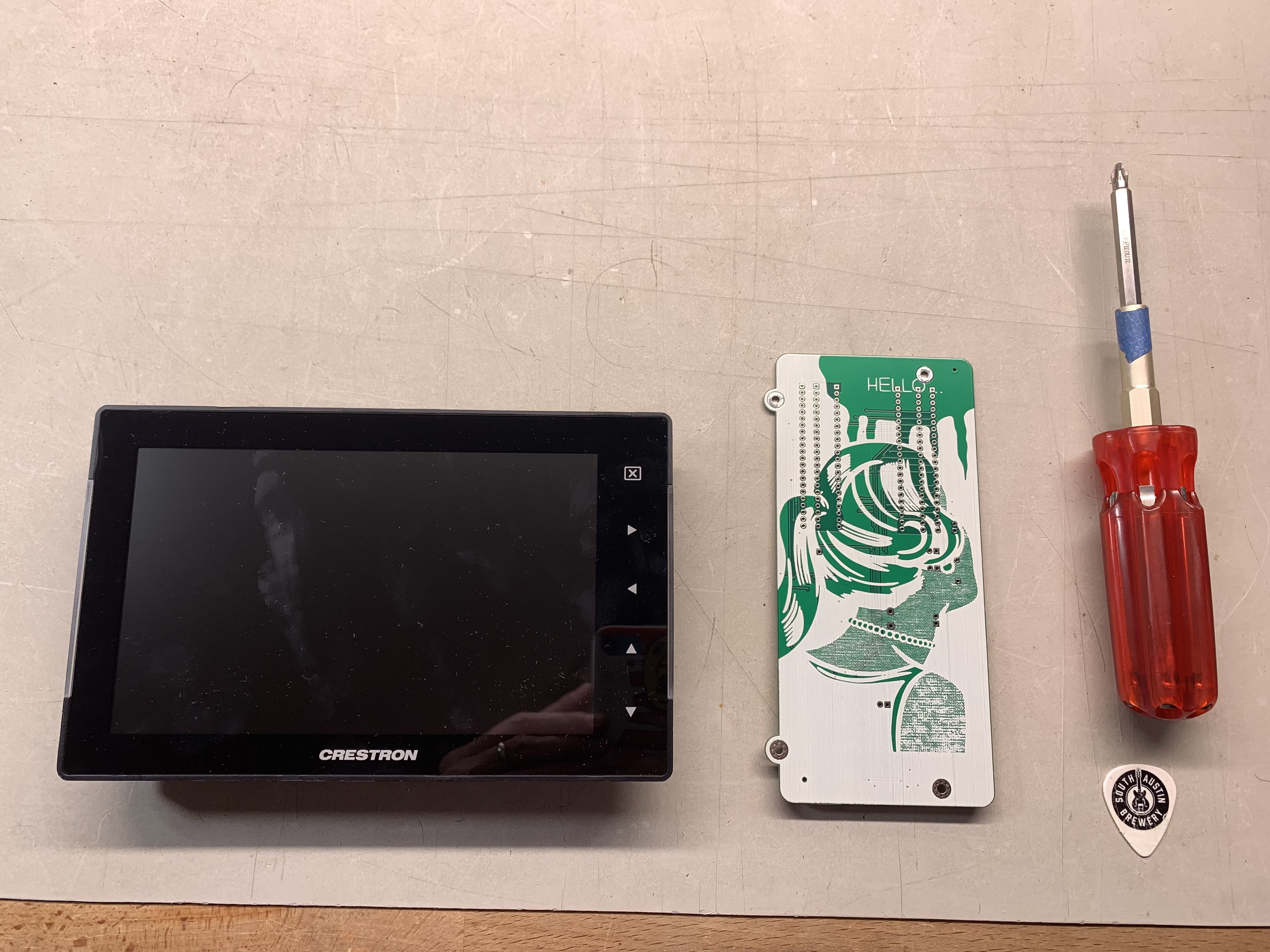
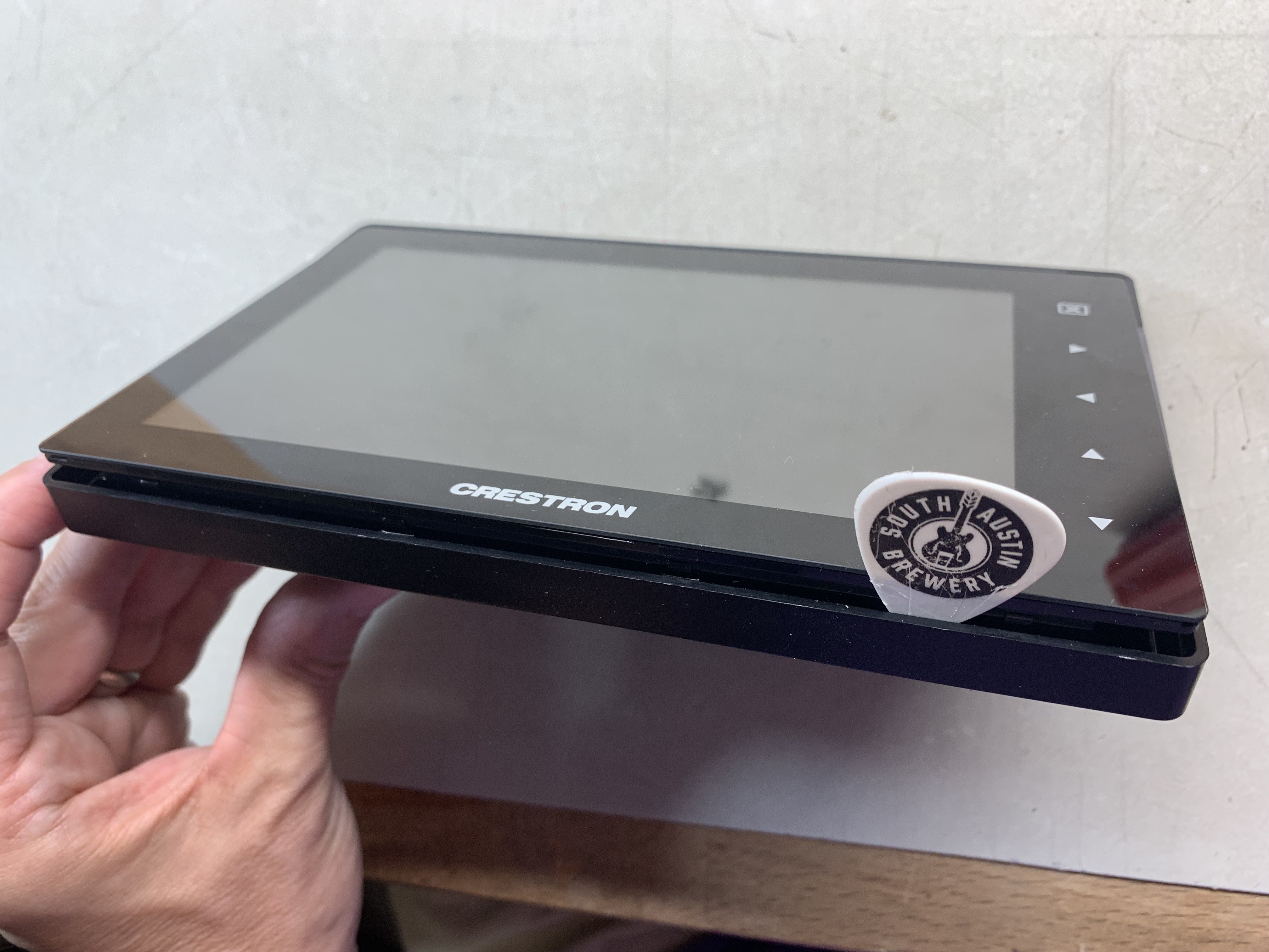
Procure a Crestron TSS-752 and a custom circuit board. You'll need a Philips screwdriver and a spudger (I use a stiff guitar pick).
![]()
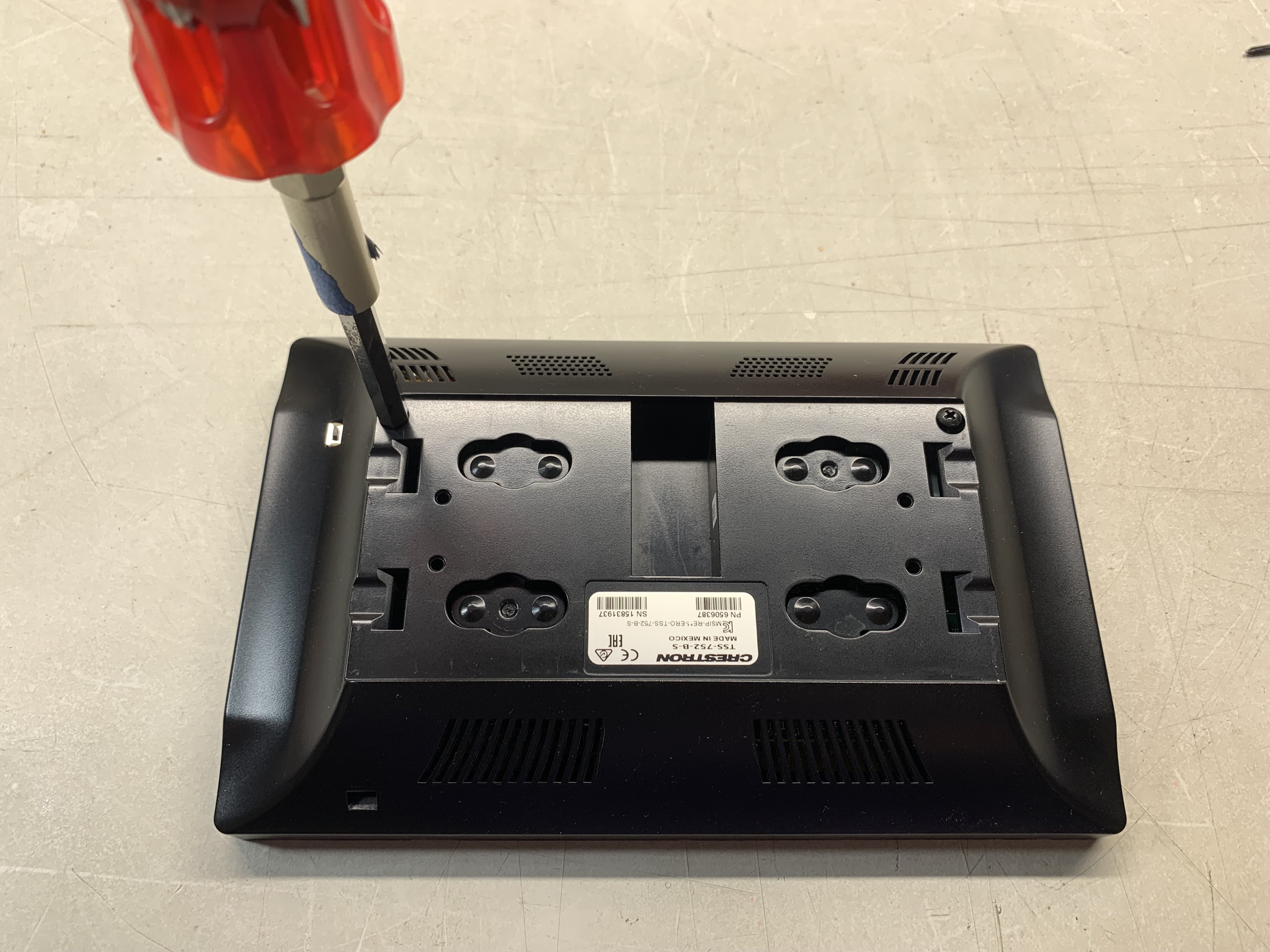
Remove two M2.5 screws with a Philips screwdriver.
![]()
On the edge with the Crestron logo, insert the guitar pick and slide it back and forth to release the clips between the housing and the display bottom edge.
![]()
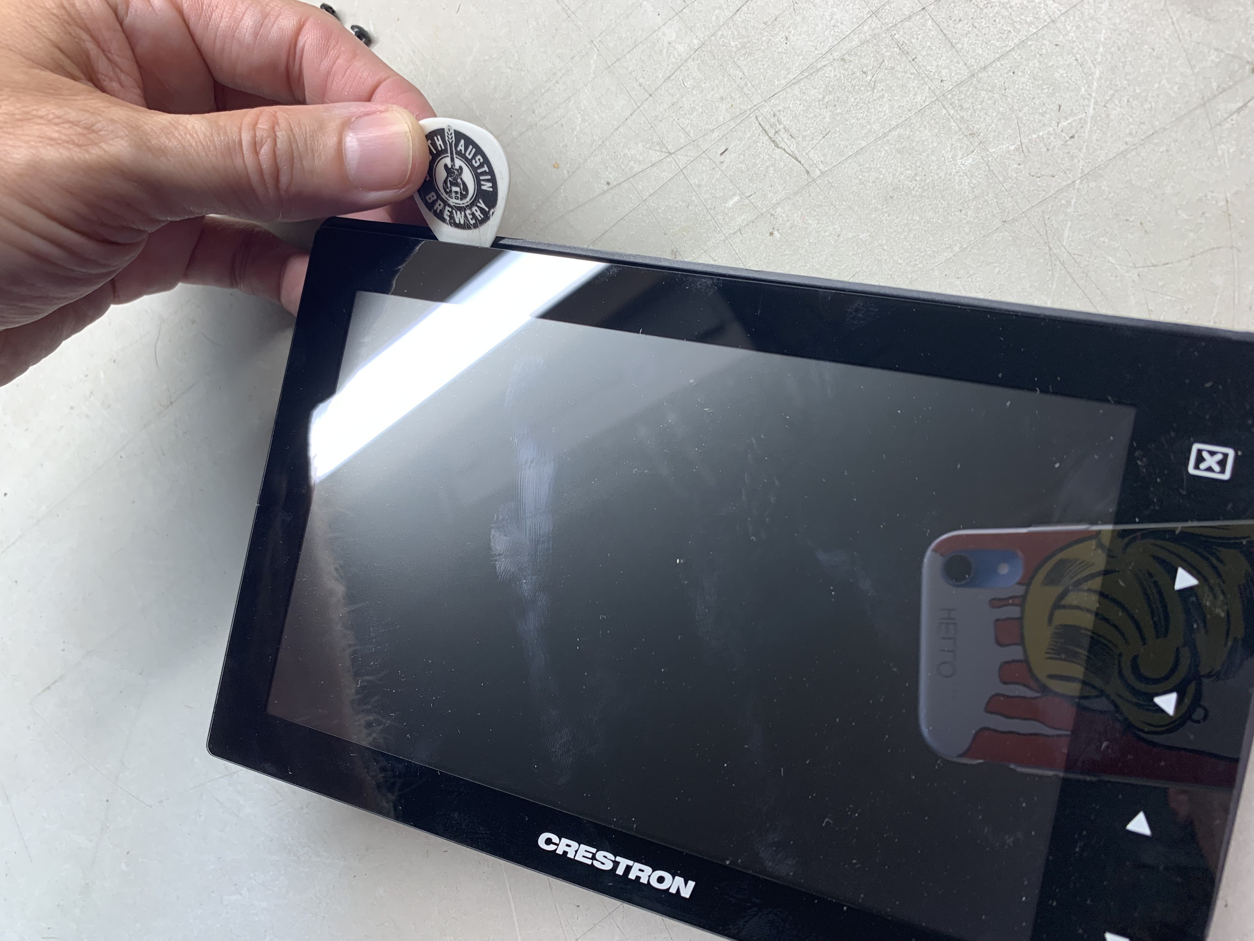
Now, do the same with the upper edge. The order of the edges is important.
![]()
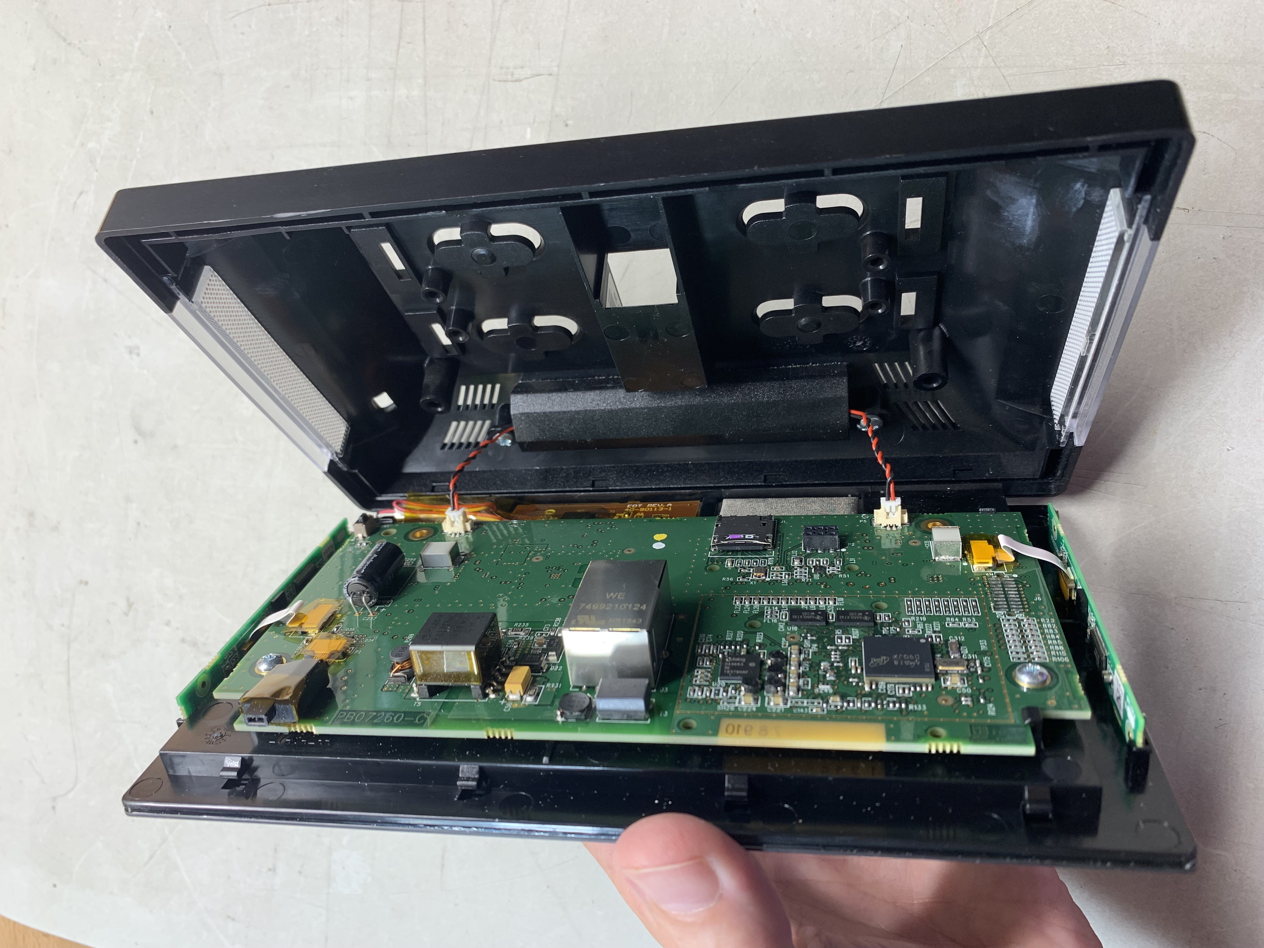
Pry off the back cover and remove the two speaker connectors (red and black twisted wires) to disconnect the main panel from the back housing.
![]()
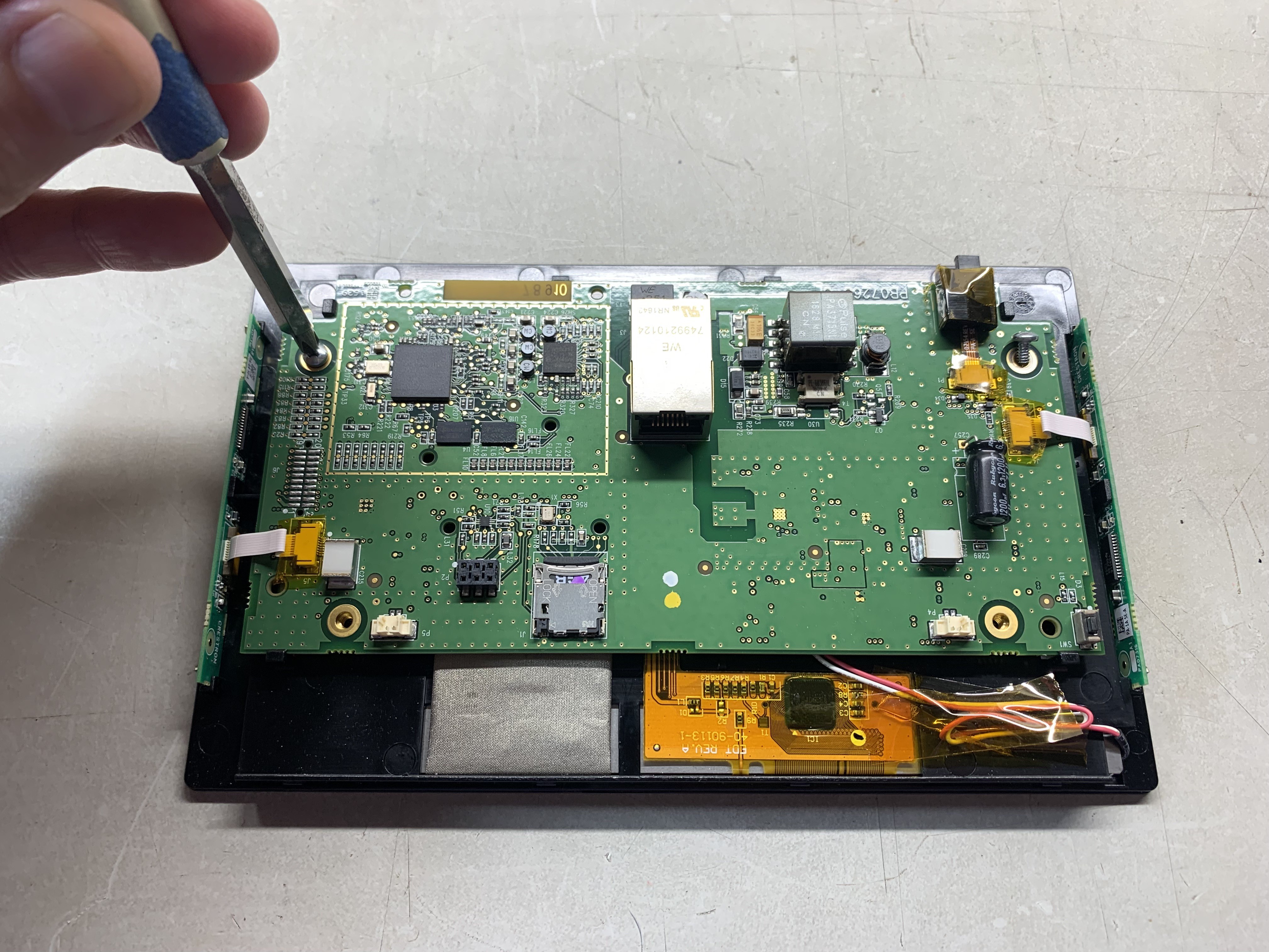
Remove two more Philips screws.
![]()
Peel off the brown (Kapton) tape from the connector cables and disconnect the flex cables. The two connectors on the left and right go to the LED and LED driver boards with I2C control. Maybe you can reuse those for another cool project. I'm not sure what the other cable goes to, but remove it anyway.
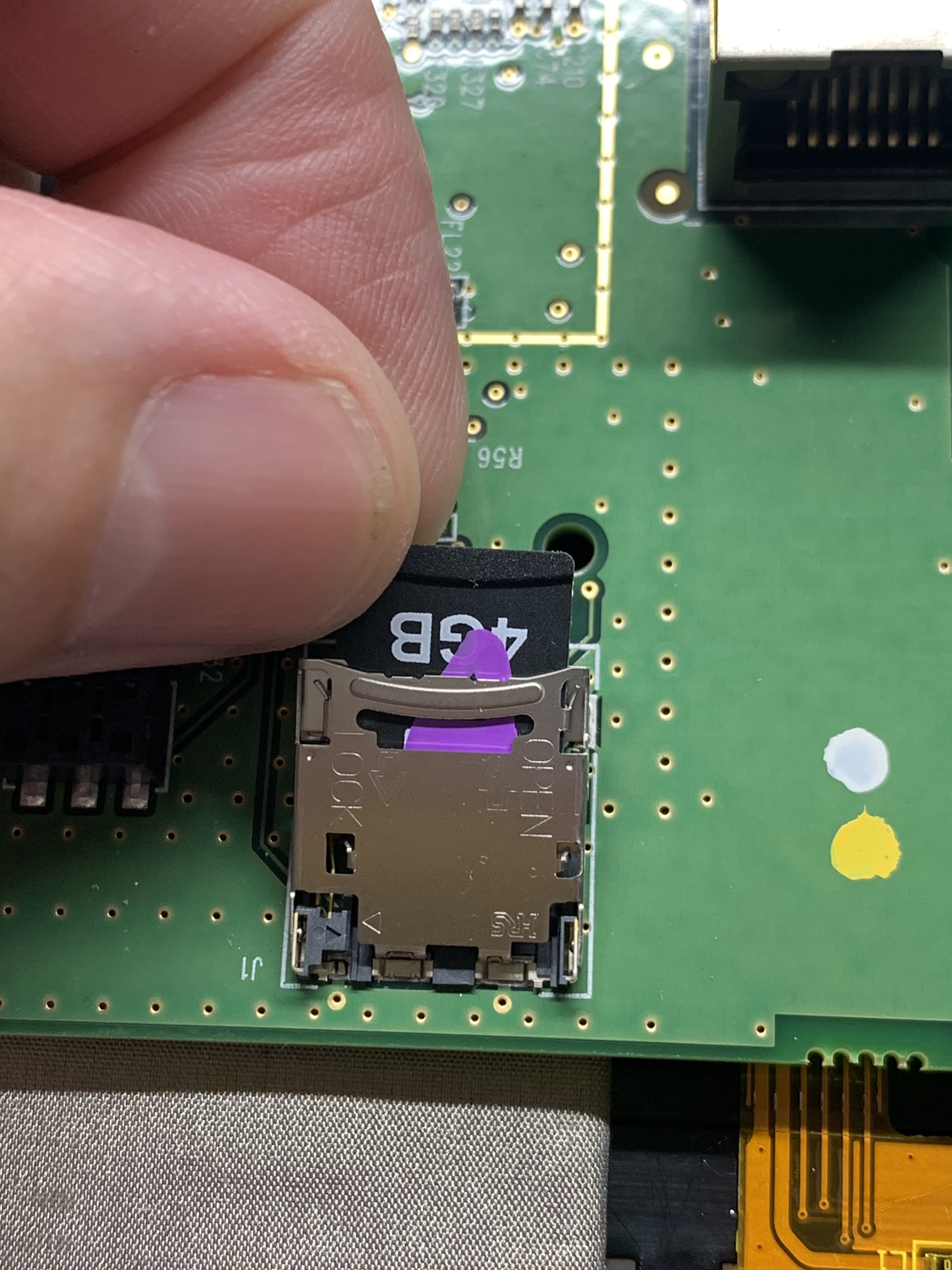
Now, remove the 4Gb memory card. It's in a weird format, but you can reformat it and use it for something else.
![]()
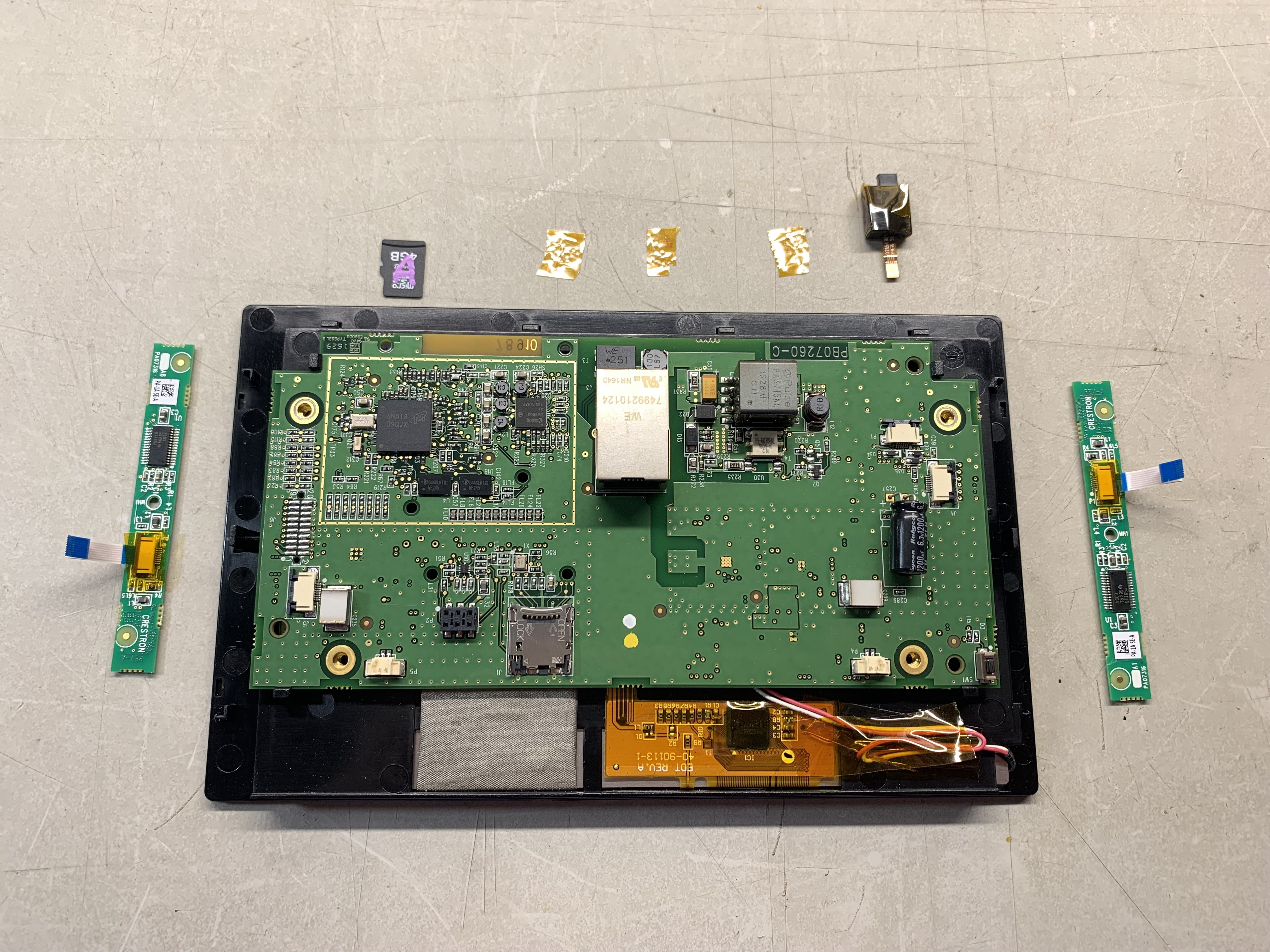
Here's the parts I removed:
![]()
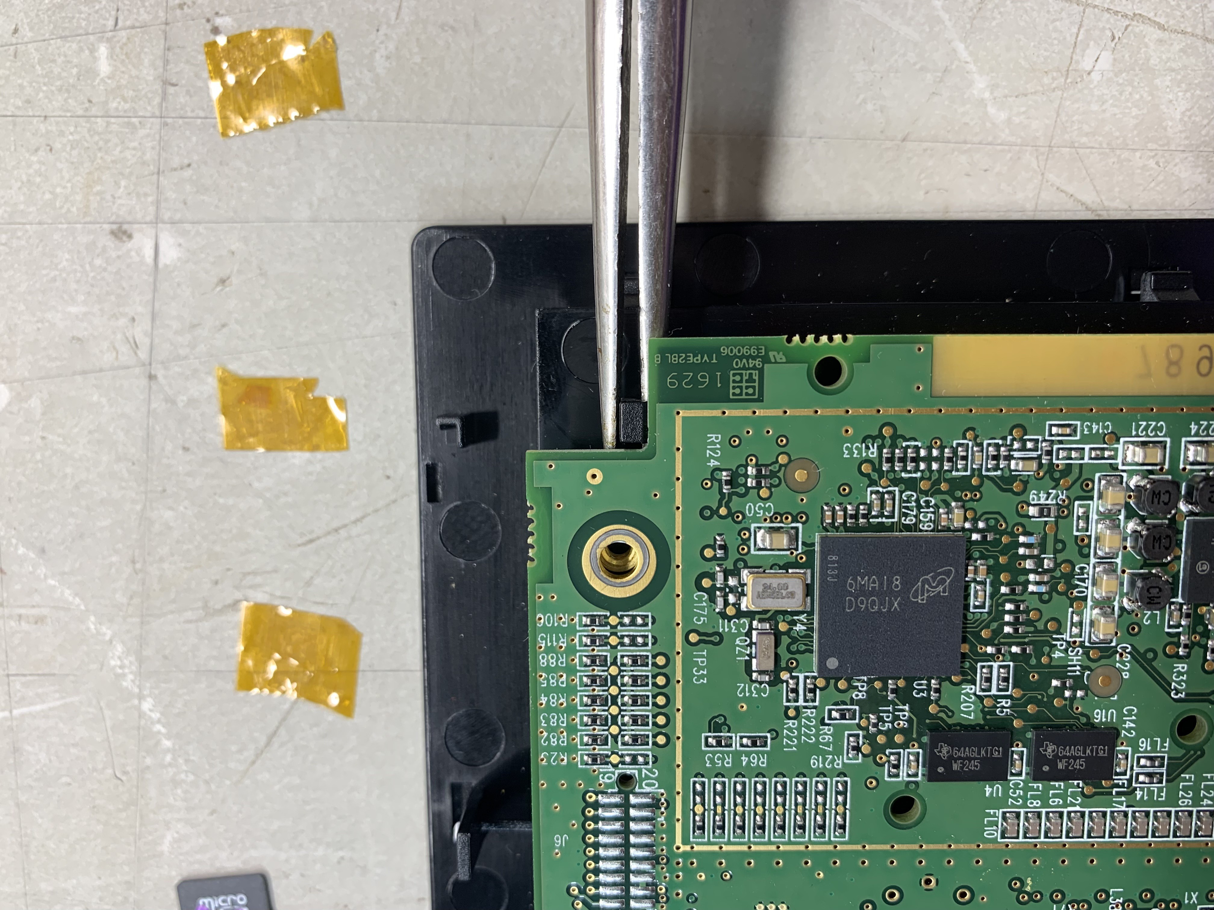
There are four plastic clips that hold the PCB to the back of the display. I used needle nose pliers to spring them aside and release the PCB. Flex them one at a time and you can get them loose.
![]()
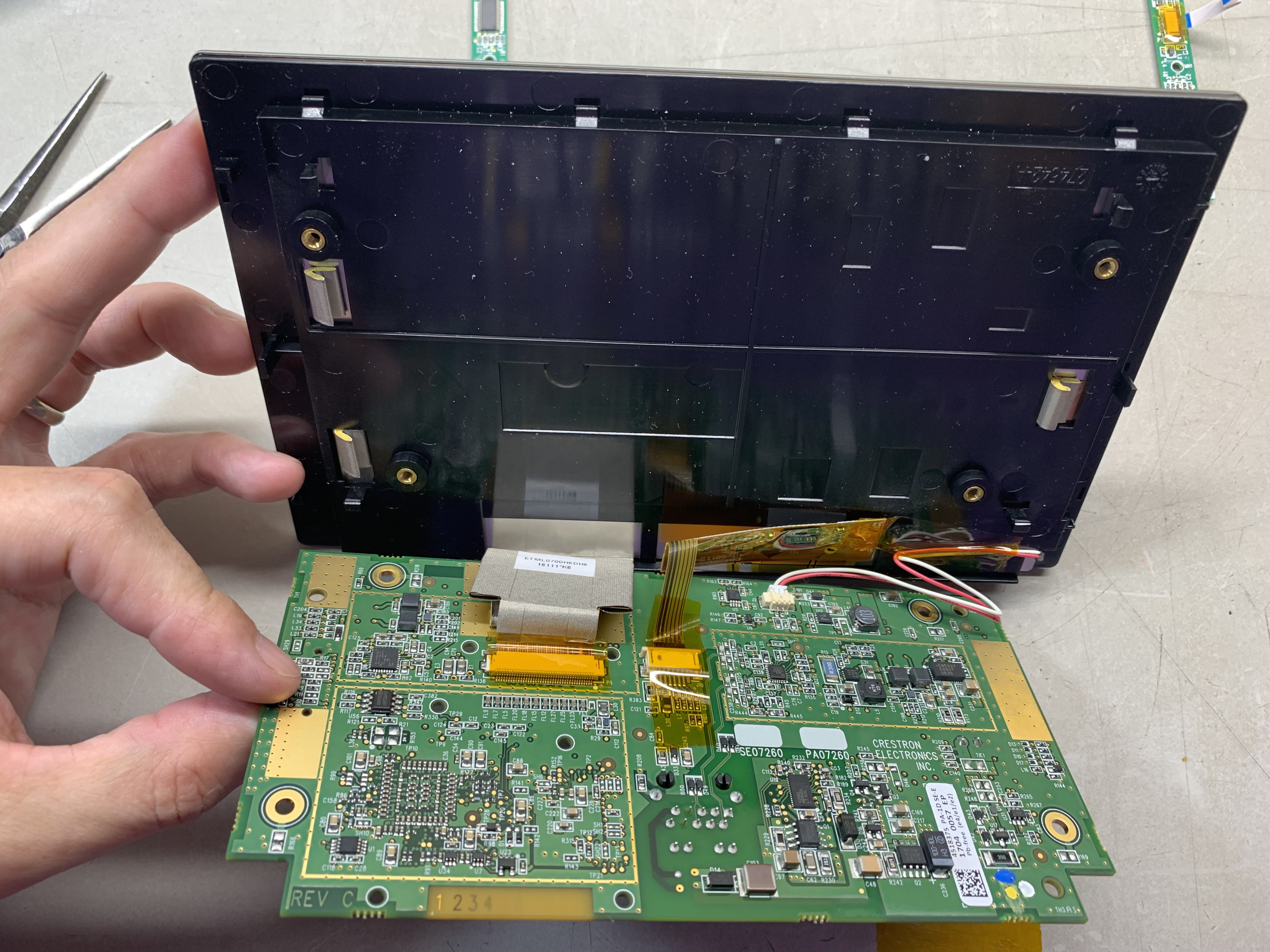
Remove some of the brown Kapton tape holding the backlight connection down.
![]()
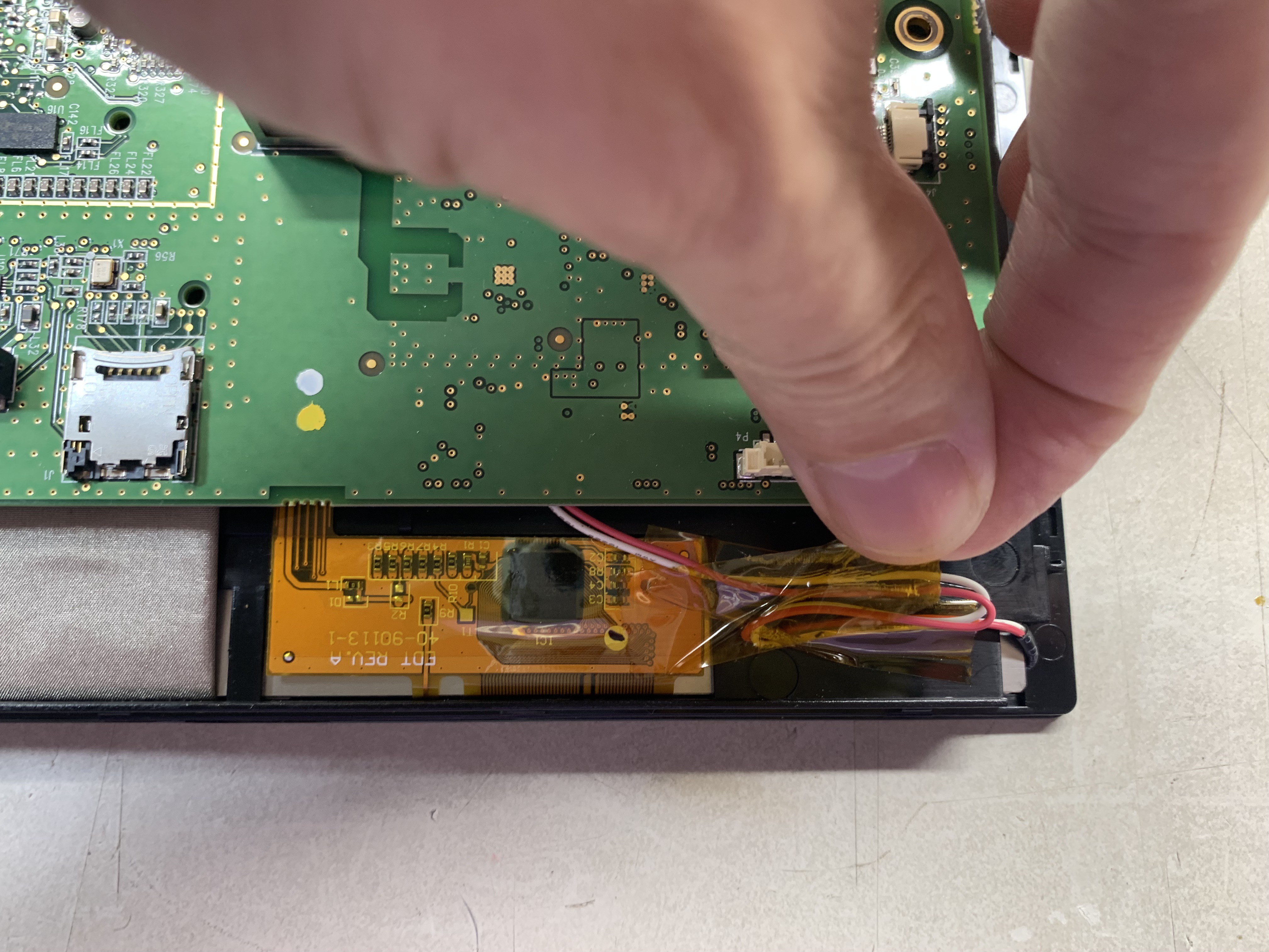
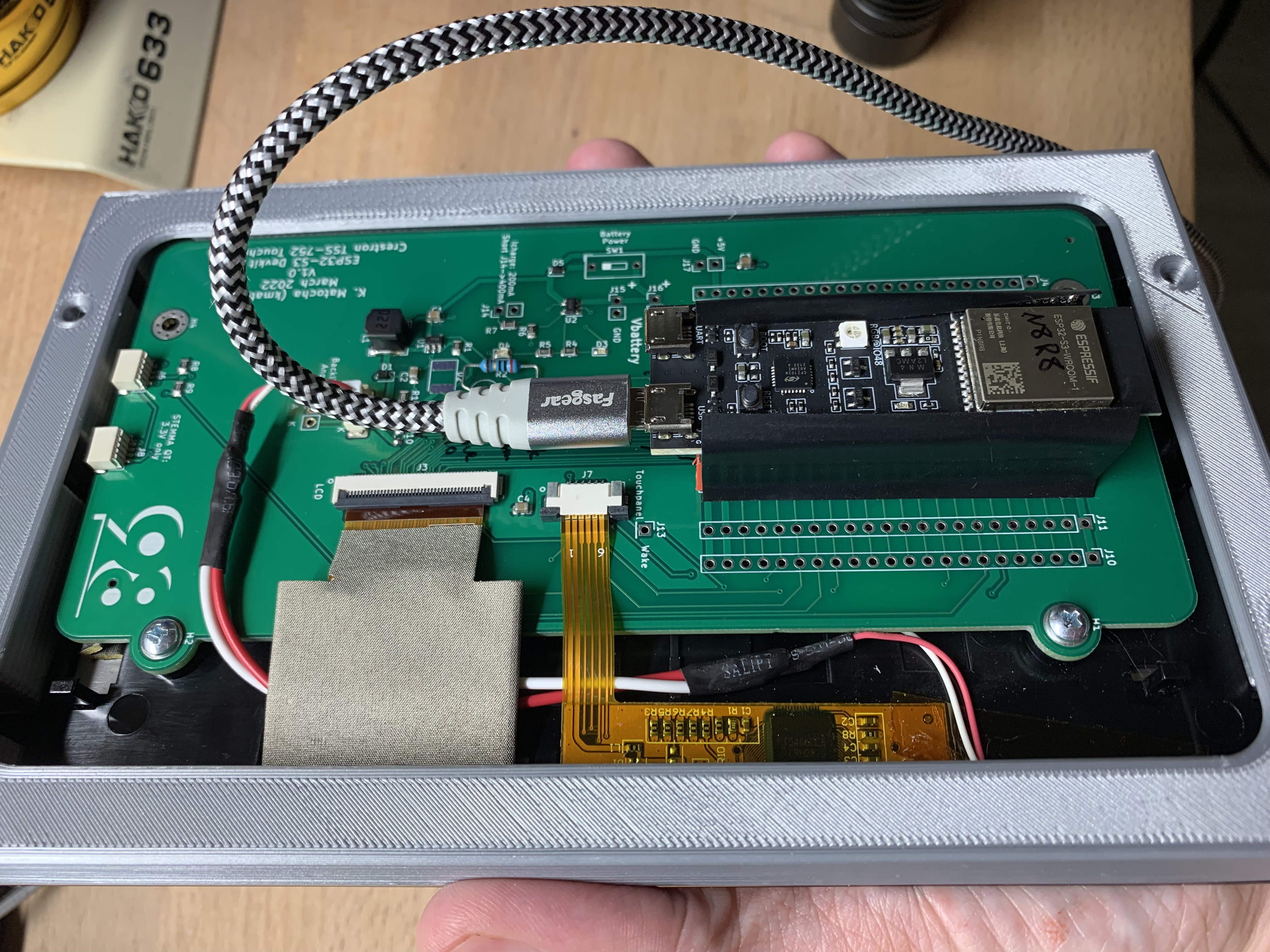
Now you can carefully hinge the PCB down (or display up) to access the three connectors (40 pin FPC for display, 8 pin FPC for touch-screen, and two-pin 1.25 mm pitch connector for backlight).
![]()
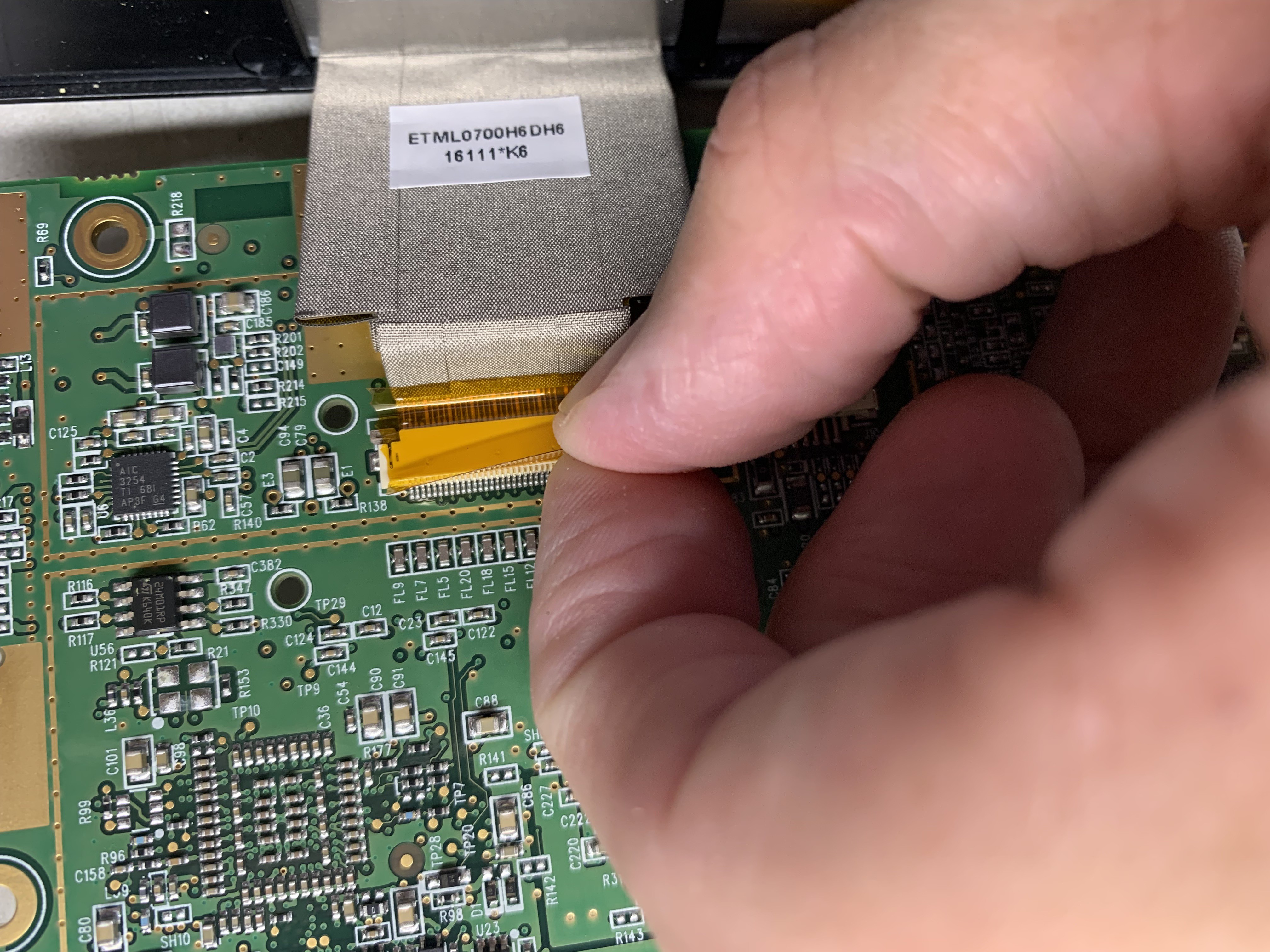
Carefully remove any Kapton tape holding the Flex connectors down. Try not to stress the flex cables.
![]()
Now slide the FPC connector latches and remove the flex connectors.
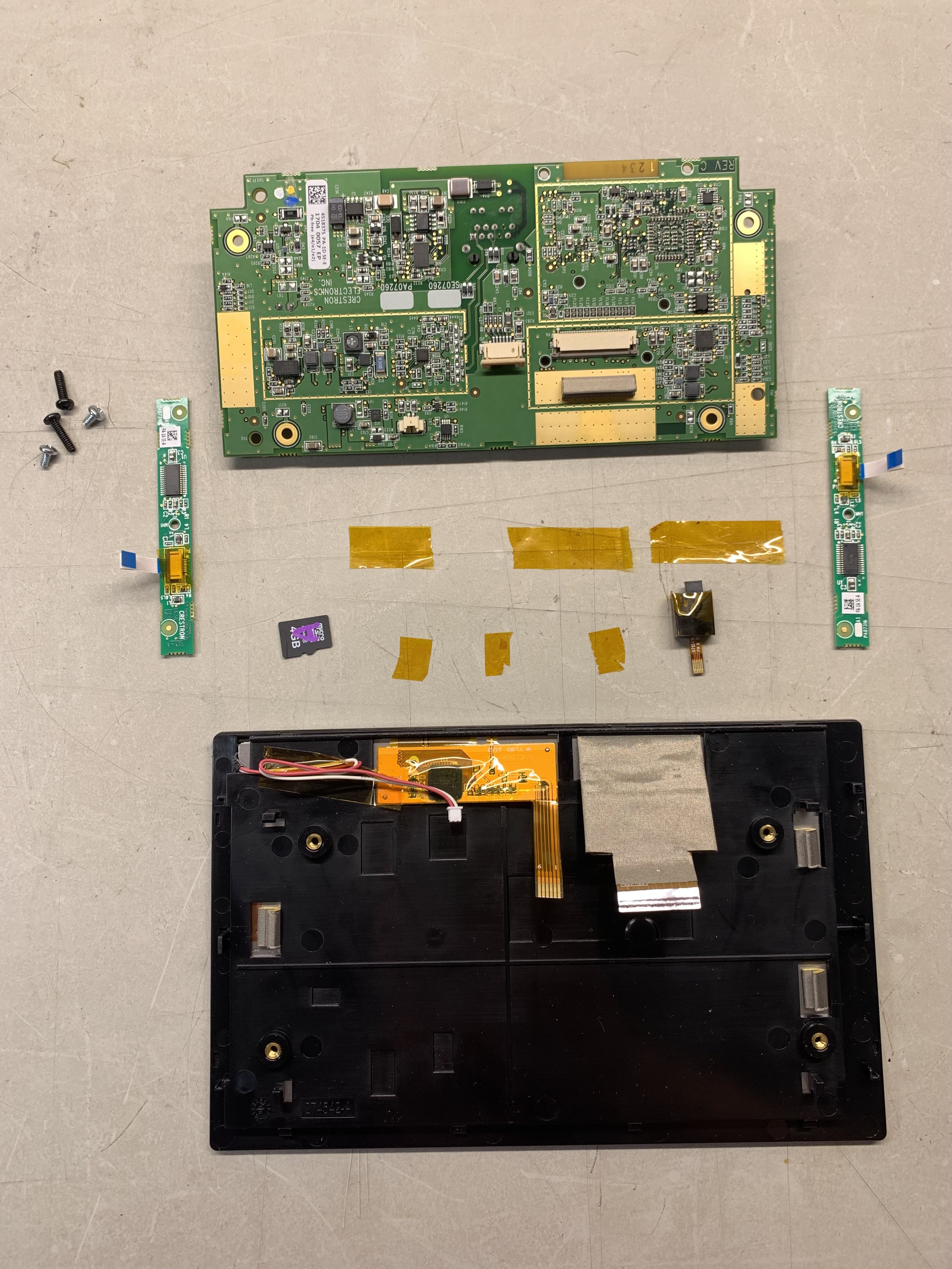
Here's the parts laid out:
![]()
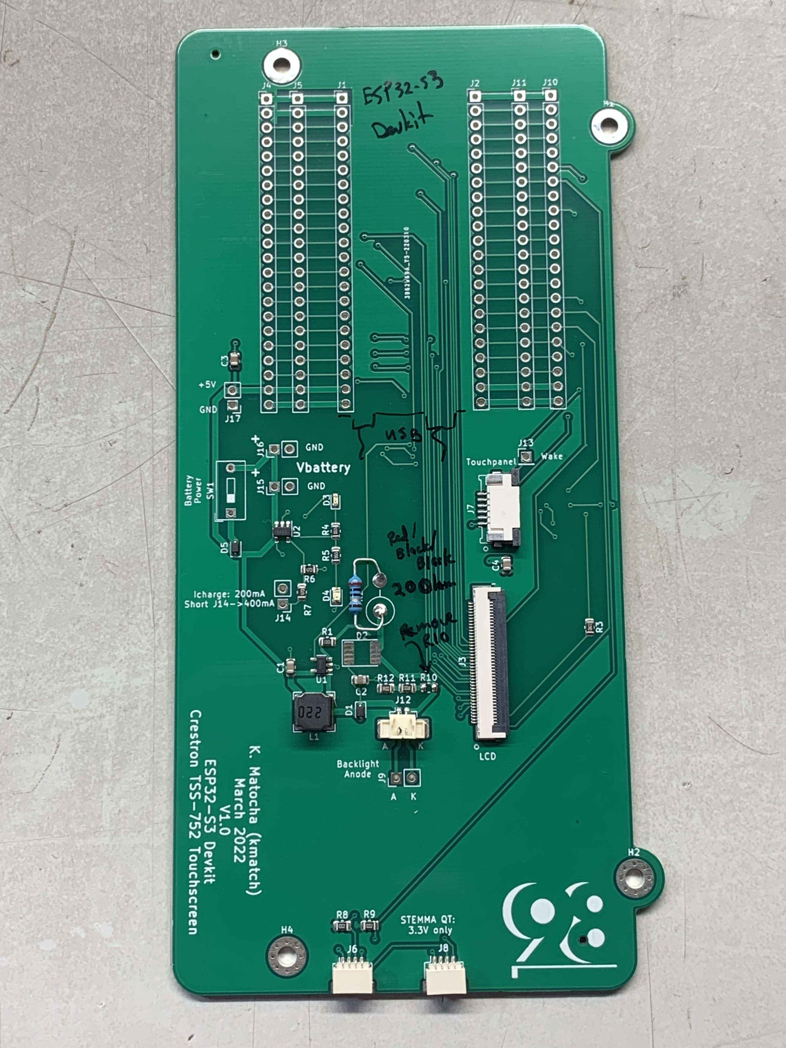
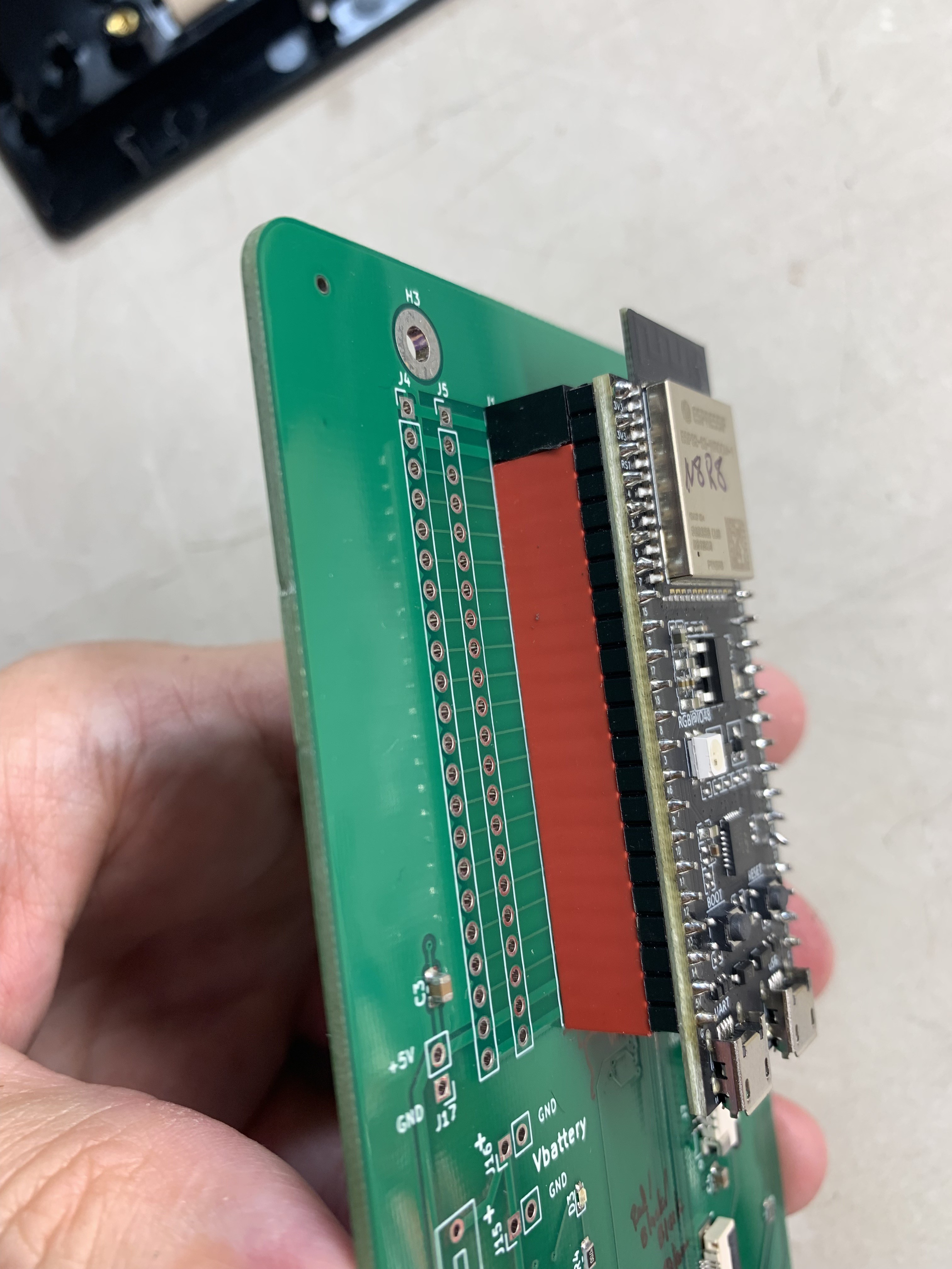
Now prepare your PCB. The original design had too much backlight current. I removed R10 and soldered a 20 Ohm resistor at position R2.
![]()
I soldered headers onto the board so that the ESP32-S3 devkit is removable if required. I didn't have 22 pin connectors, so I had to make an extra 2-pin header by cutting a longer header and sanding it to fit. Note the orientation of the USB connectors when install the devkit board. To prevent scratching anything, I put some tape on the headers.
![]()
![]()
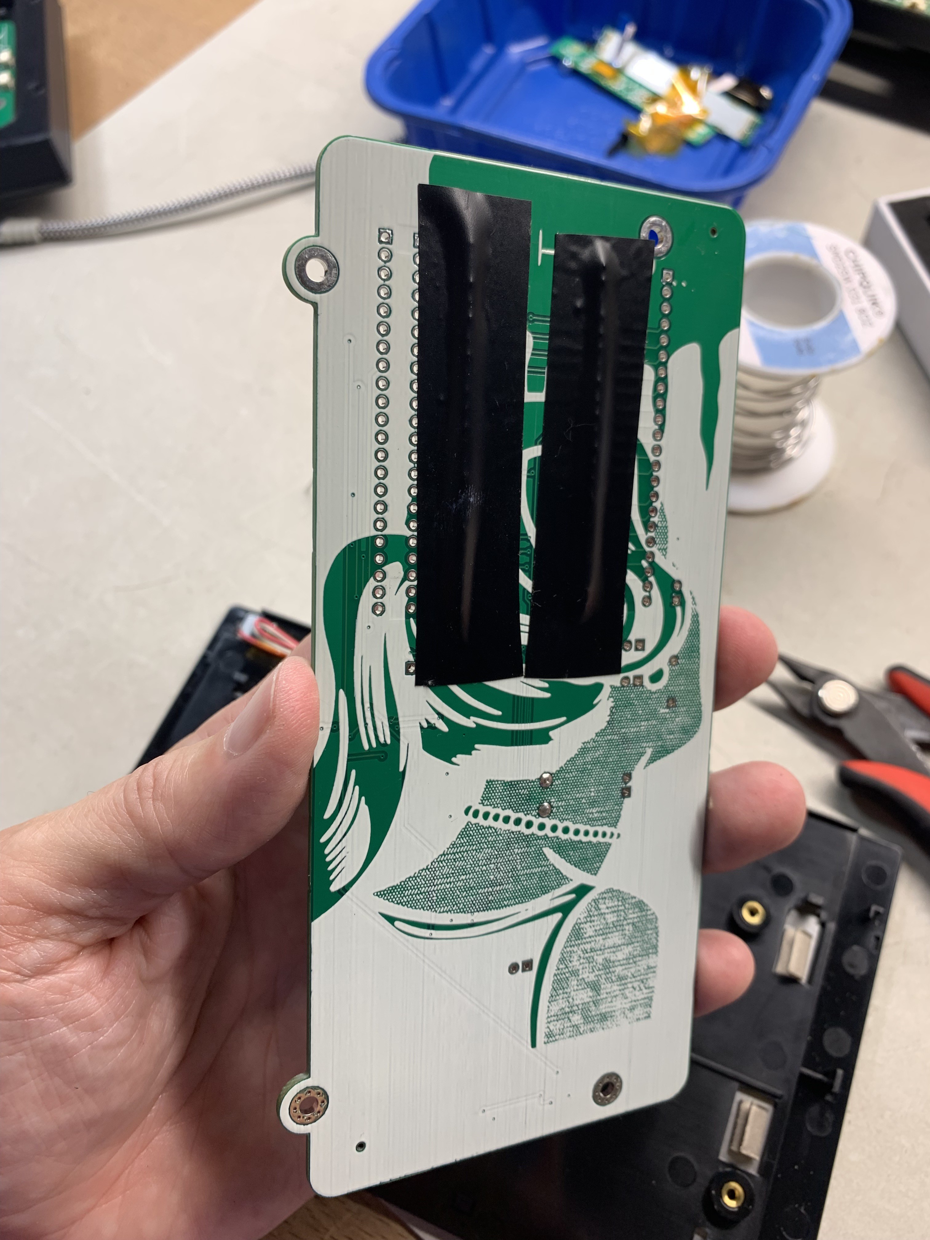
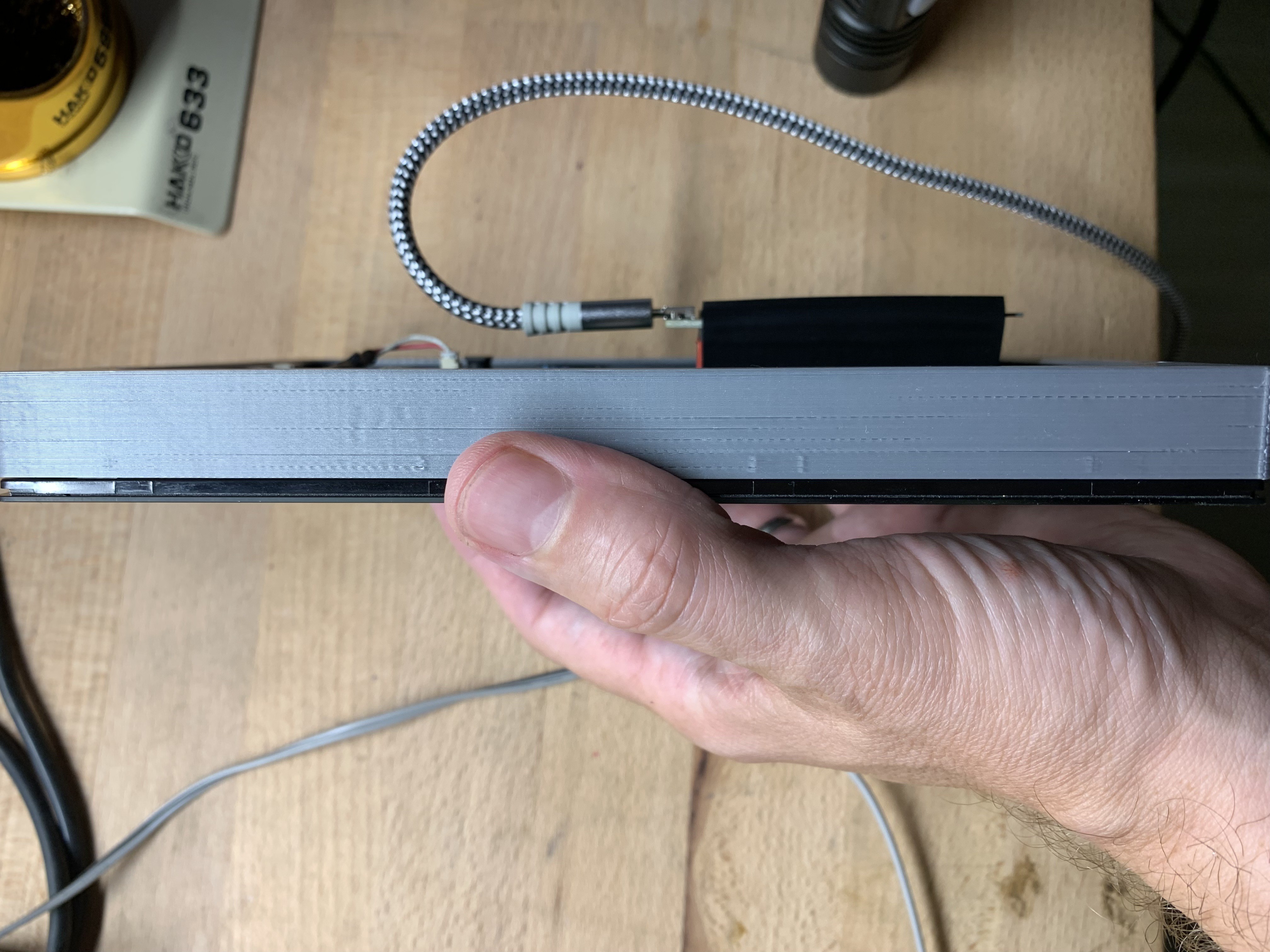
I created a thin 3D-printed bracket to make the unit easier to handle. The devkit protrudes out the back, so I put some tape on it to prevent scratching anything.
![]()
![]()
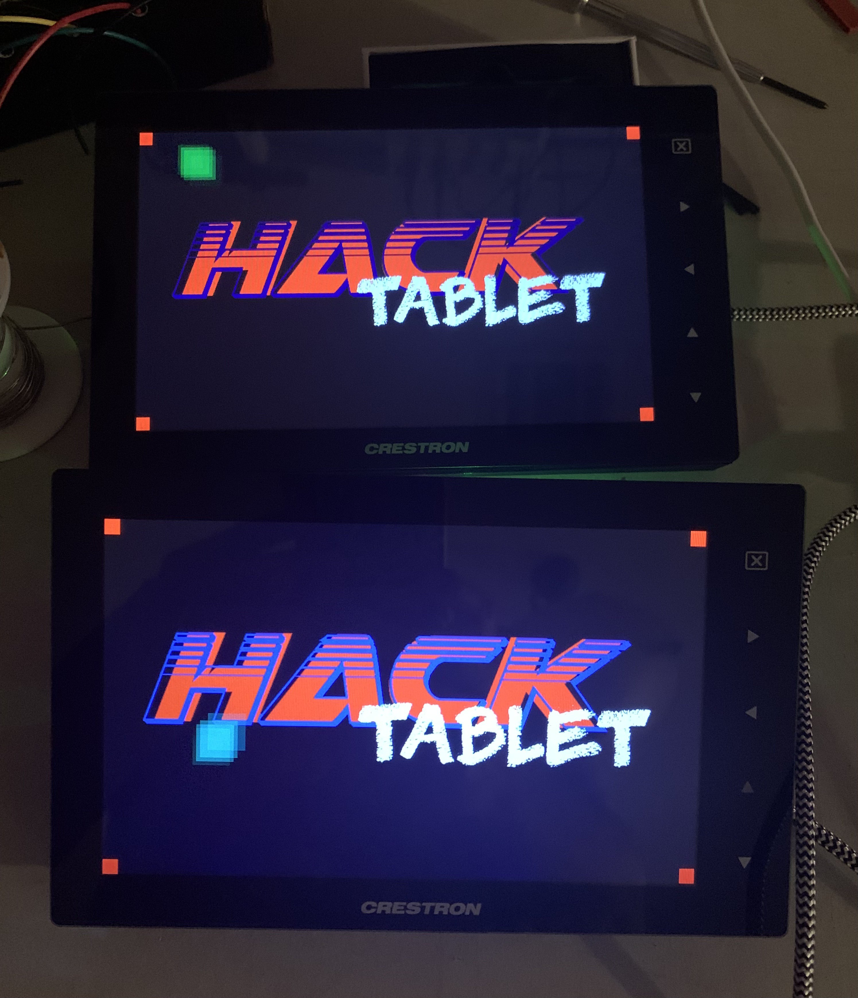
Now there's two working units:
![]()
-
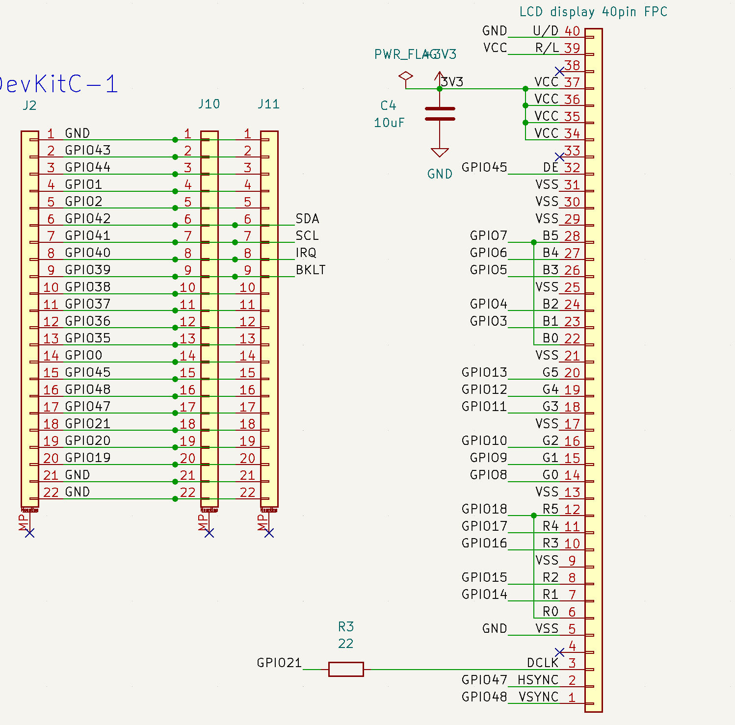
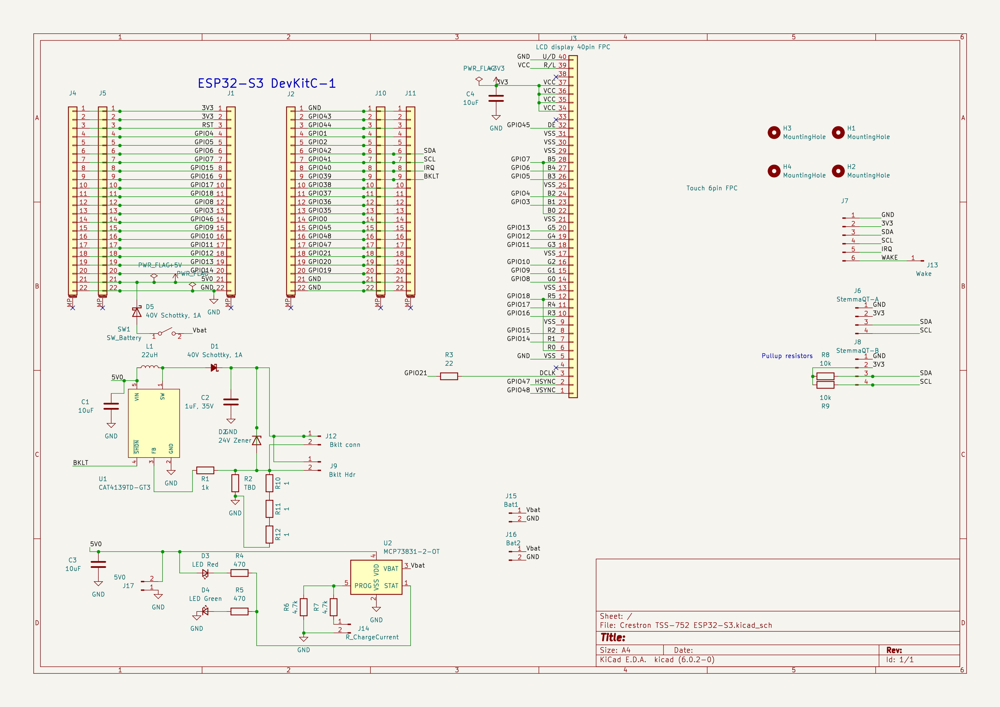
Schematic and Pinouts
07/14/2022 at 17:07 • 0 commentsHere is a summary of the pinouts between the ESP32-S3 devkit board and the I2C bus (including two Stemma QT connectors) and also the 40-pin LCD display taken from the TSS-752.
The I2C signal connections are GPIO41 (SCL) and GPIO42 (SDA). The touchscreen IRQ is connected to pin GPIO40.
The backlight enable is connected to GPIO39.
Here is the schematic for the Prototype PCB that I created for the connections between the TSS-752 extracted touch-screen display and the ESP32-S3 devkit board.
This is my first schematic so it's probably not very readable. I've got a lot to learn.
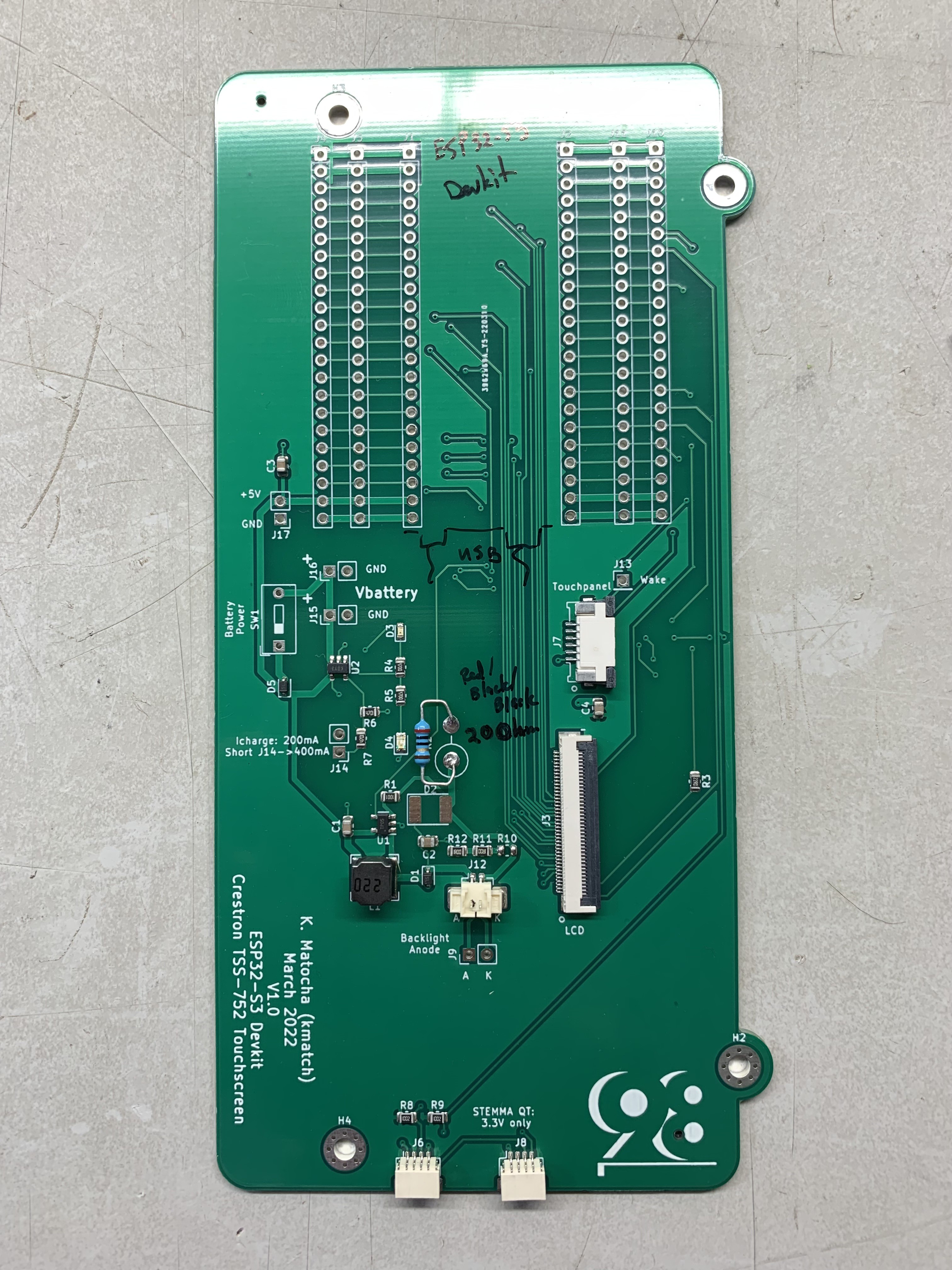
During initial testing, I found that the backlight current was set too high (and I burnt out U1), so I made a modification to the board backlight driver current setting. I removed R10 to open circuit the 3 Ohm resistance, and placed a 20 Ohm resistor in position R2. (Next time I need to provide more copper area to U1 of heat sinking.)
Also, I had to extend the wires to the backlight so that the connector would reach.
Here's an image of the board with R10 removed, and the 20 Ohm resistor placed in position R2. Also note the orientation of the devkit board, with the USB ports noted.
![]()
-
Software commit
06/25/2022 at 21:40 • 0 commentsI made a commit of my branch of CircuitPython here with the ESP32-S3 LCD peripheral updates:
https://github.com/kmatch98/esp-idf/tree/release/v4.4_rgblcd
this also depends upon some updates to the ESP-IDF for driving the LCD peripheral:https://github.com/kmatch98/circuitpython/tree/esp32s3_dotclockdisplay
These ESP-IDF changes are required to allow CircuitPython to allocate the FrameBuffer, to prevent the LCD peripheral from getting starved for data during DMA transfers, and allows CircuitPython to trigger the screen refreshes, thus preventing “tearing”. -
Minor updates
06/10/2022 at 20:55 • 0 commentsHad to take some time away, due to other personal business but thought I should update the to do list.
Now with the ESP32-S3 "bounce buffer" code from Espressif and adding the ability to trigger a refresh the display work without glitches and without tearing. Main next steps are to merge a first version and clean up the include statements so that it will build CircuitPython in a normal environment.
Other things are required to make this work. I had to make update to the ESP-IDF to allow:
1. CircuitPython to allocate the framebuffer. CircuitPython allocates all the PSRAM into its heap and then the CircuitPython core code allocates it from the heap. The ESP-IDF assumes that the framebuffer will be allocated from the PSRAM using the ESP-IDF allocation functions. I had to create a function that allowed CircuitPython to preallocate the framebuffer and pass the relevant address into the display init function.
2. I added a function so the the CircuitPython display can trigger the refresh. The ESP-IDF just refreshes continuously. I had to add this new function so that the display would not refresh while the memory was being changed, which caused tearing.
3. I need to create an issue on the ESP-IDF to request the abilities above.
4. I'd like a way to evaluate the CircuitPython frame rate. So far I haven't found any obvious way of measuring it.
HACKtablet: Crestron TSS-752 Teardown + Rebuild
Tearing down a Crestron display conference room controller, the second. And making it into a CircuitPython device.