Let's test some 6DJ8's in order to sort out the meter resistance.
Here's the data collected in prior log. This is a dual triode
Pinout:
1
A
Plate 1
2
B
Grid 1
3
C
Cathode 1
4
D
Heater
5
E
Heater
6
F
Plate 2
7
G
Grid 2
8
H
Cathode 2
9
J
Shield
The letters correspond to how the tester refers to the pins.
The tube data lists these values:
Element 1
Element 2
Type
2
2
Filament
6.3
6.3
Plate
21
21
Top (Plate)
AB
FG
Bottom (Cathode/Filament)
C(E)
(E)H
Type 2 means, a B+ of 30v, plate R of 820 ohm and meter R of 360.
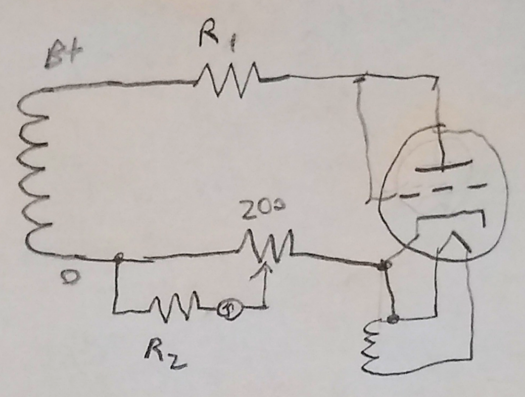
Test circuit
In order to test, I'll take the fact that the meter+R2 much higher than the 40ohm of the pot, and omit it initially.
With this, I'll use the 200ohm pot connected from power supply negative to cathode, and 820 ohm set on 10W decade resistance boxes from plate(plus grid) to the power supply positive. Then we'll be able to measure a voltage across the power supply negative and pot wiper.
With a 200ohm pot value of 21/100, this means 42ohm from low to wiper.
Measuring that voltage represents the voltage across R2 and the meter resistance. Knowing that a good value results in 0.5mA, we can calculate the total resistance.
Each line represents a different tube, measuring that voltage, along with the current through the circuit. This is just from the simplified circuit for the emission test. (Not open, leakage or short tests)
Test
E1 V
E1 plate I
E2 V
E2 plate I
1
1.00
23.8
1.03
24.6
2
1.05
25.1
1.04
24.8
3
1.07
25.5
1.04
24.8
4
1.04
24.8
0.88
20.9
5
1.02
24.4
1.04
24.8
6
1.06
25.2
1.07
25.4
7
1.06
25.3
1.06
25.3
8
1.05
25.0
1.07
25.4
I'd prepared to test more, but stopped after 8 because things were so clear. There's even a failure of element 2 in number 4.
One surprise is that the current is so high. The 6DJ8 is specified at 27mA max, with 15 typ.
That the voltage comes out to just over 1V doesn't seem like a coincidence.
If we take 1v as passing (above 0.5mA, this means the resistance needs to be less than R = V/I = 1/0.0005 = 2000. Removing the selected series R we get a meter resistance of 1640 ohm.
If the meter were actually 1.5K, then the resulting current would be 1/1860 = 0.54mA, which seems like it may be in the good territory on the display.
If the meter were actually 1K, then the resulting current would be 0.74mA, right in the middle of the good side. (I notice that in the instructions for testing new tube types, it indicates a be default reading right in the middle of good, so 0.74mA makes sense)
Looking at the triode with an off value, with a 1K meter, it would be 0.64mA, probably reading good. With a 1.5K meter, it would be 0.47mA, probably in the bad territory.
Seems like we've narrowed it down in that 1 or 1.5K region. Given that, we can confirm that omitting it from the circuit was reasonable, reflecting only a 2 ohm difference. At 1% of full scale, i can tell you on this pot, that this is well within tolerance of manual setting of the pot.
This all seems to suggest to me that about 1.0V is that passing target.
With a little uncertainty about the threshold and test current, it think I need to test another model of tube, with different settings.
I have a set of tubes to test for an amplifier. I'll go through them.
5V4G
First is the rectifier/dual diode used in power supply.
Pinout:
1
A
NC
2
B
Heater 1
3
C
(Missing)
4
D
Plate 1
5
E
(Missing)
6
F
Plate 2
7
G
(Missing)
8
H
Heater 2 / Cathode
The letters correspond to how the tester refers to the pins.
The tube data lists these values:
Element 1
Element 2
Type
3
3
Filament
5
5
Plate
25
25
Top (Plate)
F
D
Bottom (Cathode/Filament)
(H)
(H)
Not listed in there, but all other switches are middle, which is connected to the other side of the filament voltage, "positive".
Type 3 means, a B+ of 30v, plate R of 0 ohm and meter R of 1500.
6SN7 *2
A dual triode, used in preamp and phase inverter.
Pinout:
1
A
Grid 2
2
B
Plate 2
3
C
Cathode 2
4
D
Grid 1
5
E
Plate 1
6
F
Cathode 1
7
G
Heater 1
8
H
Heater 2
The tube data lists these values:
Element 1
Element 2
Type
2
2
Filament
6.3
6.3
Plate
26
26
Top (Plate)
DE
AB
Bottom (Cathode/Filament)
(F)(G)
C(G)
Not listed in there, but all other switches are middle, which is connected to the other side of the filament voltage, "positive". It's puzzling that F is bolded, but not C. Seems like F shouldn't be.
Type 2 means, a B+ of 30v, plate R of 820 ohm and meter R of 360
5881 (6L6?) *2
A beam pentode used as output drivers.
The catch here is that with the tubes I have, no markings are visible. The version w3 schematics these are marked as 5881, but the tube shape doesn't seem right, and doesn't match the pictures. Other sources suggest they could be 6L6. So I'll look up values for both and we can see what it looks like.
Pinout:
1
A
Shell / NC
2
B
Heater
3
C
Plate
4
D
Grid 2 (screen)
5
E
Grid 1
6
F
(Missing)
7
G
Heater
8
H
Cathode / Grid 3
Both 5881 and 6L6 share the same pinout, so that's a good start.
The tube data lists these values:
6L6
5881
Type
3
3
Filament
6.3
6.3
Plate
27
20
Top (Plate)
CDE
CDE
Bottom (Cathode/Filament)
(G)H
(B)H
Not listed in there, but all other switches are middle, which is connected to the other side of the filament voltage, "positive". It's interesting that the only pinout difference here is the "polarity" of the filament, which wouldn't seem to matter.
Type 3 means, a B+ of 30v, plate R of 0 ohm and meter R of 1500.
Reference 6DJ8 / ECC88
As we still have one missing value from the circuit, I'm going to use a reference tube that I have a lot of, in this case a set of Amperex 6DJ8/ECC88 's. While these are all used, my hope is that by testing a bunch, I can find a common value and build certainty with that
This is a dual triode
Pinout:
1
A
Plate 1
2
B
Grid 1
3
C
Cathode 1
4
D
Heater
5
E
Heater
6
F
Plate 2
7
G
Grid 2
8
H
Cathode 2
9
J
Shield
The letters correspond to how the tester refers to the pins.
The tube data lists these values:
Element 1
Element 2
Type
2
2
Filament
6.3
6.3
Plate
21
21
Top (Plate)
AB
FG
Bottom
(Cathode/Filament)
C(E)
(E)H
Not listed in there, but all other switches are middle, which is connected to the other side of the filament voltage, "positive". The bolding didn't make sense, so I updated here to be what I think it is
Type 2 means, a B+ of 30v, plate R of 820 ohm and meter R of 360.
We can use all of that, distilled down to the basics to do the test without all the switches and sockets.
Test Circuit
The generic test circuit is:
Note that if the device is a pentode or pentagrid converter, all the grids are weird together with the plate.
The values for each type are:
Type
B+
R1
R2
1
30
3600
0
2
30
820
360
3
30
0
1500
4
250
2500
1500
Looks like R1 could burn some power, so probably best to keep the test short if you can't find 10w ones.
I'll also need a 200 ohm wire wound resistor which I found. If you don't have one, you could use a decade resistor box, or substitute in fixed values. Looks like whatever you pick should be able to tolerate 25mA, or 1.25W (modes 1,2,3 only), which should only happen if the tube has a short.
The original tester uses AC for the supply, relying on the tube as a diode, and the averaging nature of an analog meter to smooth out the pulses. I'll just use DC, which also makes for easy current limiting. I think you can use AC with a digital ammeter, as long as you set it to ac RMS.
We still need to figure out the meter resistance, which we'll get to soon.
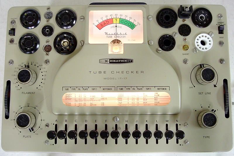
Vacuum tube testers present themselves as rather mysterious. You plug in a tube, look up some esoteric numbers, set some knobs, flip switches back and forth and watch a meter which is simply labeled with a fail to pass gradient, without any units or other info. So what is it doing and how does it work?
Thankfully, there are lots of reference designs out there with documentation. Perhaps the easiest to find are the Heathkit models. These were sold as kits to hobbyists to assemble themselves. Their instructions include schematics, BOMs and some theory information. Digging around shows that all the common versions use basically the same circuit, with some minor variations. I'll look at the IT-17 and IT-21 models.
Theory
The manuals outline the types of tube testing. I'll let you read them directly for more details, but the key take away is that these are like most common tube testers, which test for shorts, Leakage, Opens, and Emission (which covers filament as well)
HeathKit IT-17 This scan has easier to read schematics, but doesn't include the full assembly instructions.
HeathKit IT-21 This scan has the full assembly, but the fold out schematics are split between pages.
Images in this post are from these files.
Shorts and Leakage
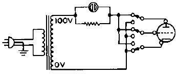
Buried into the details is a note that the short test checks for connections between pins that are less than 250Kohm and leakage check is for less than 2Mohm. So the word "short" is a little loose. Anyway, the simplified circuit for this:
This uses a 100V test voltage across pairs of pins, with a series neon bulb (there is also an R not shown) to test for shorts. If the neon illuminates, it means there is a resistance below a certain level(250k/2M). A neon is used here because it takes very little current. Switches are used to change which of the pins the circuit is connected to. This is why during a short test, you are flipping the switches back and forth, to get all the combinations. Given the wide range of number of tube pins supported, it explains why there are so many switches on the tester. (13 for this model)
Emission
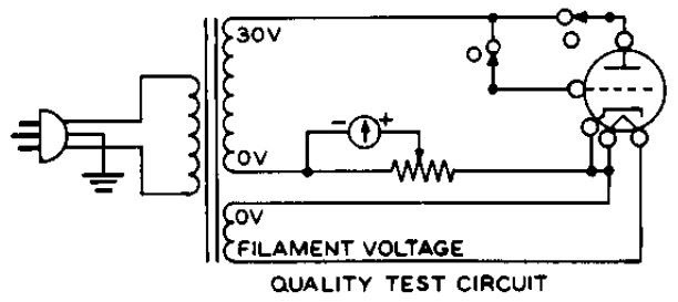
To test emission, the meter is used, along with a setting on the pot to check that the right amount of current is flowing from cathode to plate. But for those familiar with curve tracers, where is the seting for the grid(base/gate)? Digging through the theory section, we find that the common emission type tester doesn't test it as a 3/4/5 terminal device, instead wiring it as a 2 terminal diode. Here's the simplified circuit:
The switches are shown in the position for testing emission. You can see the filament is being run as normal, and the meter is measuring cathode current, while the plate and grid(s) are connected to the voltage source. Not shown are the series resistors, or selection of plate voltage and resistor
The pot acts like a range switch on a multimeter, more on this later.
Opens
But how do you measure opens, when most of the elements are open by design within the vacuum? The answer is to see if the emission test changes based on which elements are acting like the plate.
By connecting all the elements(besides cathode and heater) together and high, they are all acting like the plate. Obviously a grid isn't going to be very effective compared to the actual plate, but it has an effect. The emission test is run, and one at a time, each element is disconnected. With each disconnect, the cathode current(shown on meter) should change somewhat. When each is disconnected, that element is removed from the larger effective plate, changing the value. The instructions tell the user to look for any movement of the needle, no matter how small. If the meter doesn't move at all, it means that element is already disconnected.
In this way, we can check for opens on the plate and each of the grids. An open on the cathode would have resulted in a failure of the emission test.
For the filament, switches so that each of the filament pins are connected through the neon lamp, with it lighting for a good connection. Functionally this is the same as the short test, but measured through the low impedance filament.
Calibration/Alignment
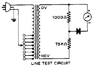
These devices use direct transformer outputs, without any regulation. Because of this, variation in wall line voltage would change the test voltage for the emission test, altering it's results. Today we'd just use a regulated voltage, but back then, it would have added way more complexity and cost as accurate voltage regulation wasn't simple. Instead, they use the meter, along with a rotary switch and lots of taps on the input side of the transformer. This allows the user to switch which input tap to match the voltage they have.
If you imagine a transformer which has 120 and 240 volt input taps, it's like that, but instead this has 95, 100, 105, 110, 115, 120, 125, 130 and 135 volt input taps. Kinda wild from a modern perspective.
A simple voltage divider is used on a secondary for the ammeter.
Practical
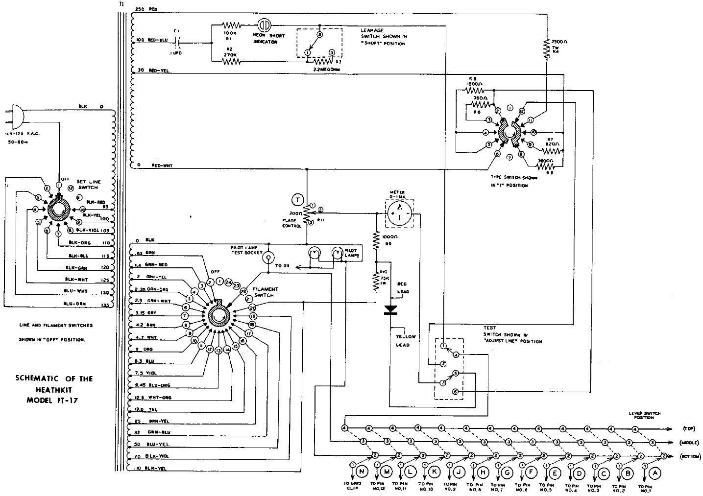
Now to the practical. Here is a handy picture of the full schematic. The original PDF is in the above/attached files.
We can break this circuit down into pieces.
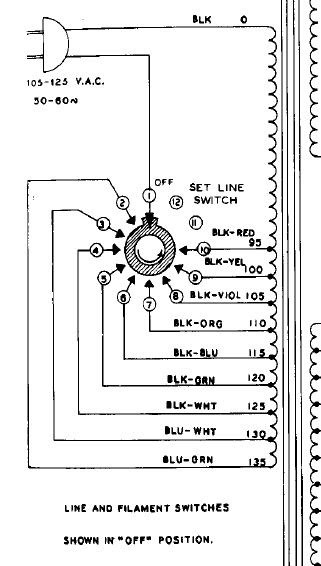
Input line switch
The input line switch serves to calibrate the output voltages correctly. While we can use a regulated power supply and ignore the section, is worth at least looking at the details.
As described before, this is simply a rotary switch selecting which input tap to use. This switch also serves as the power switch. (Note the lack of fuse, yikes!
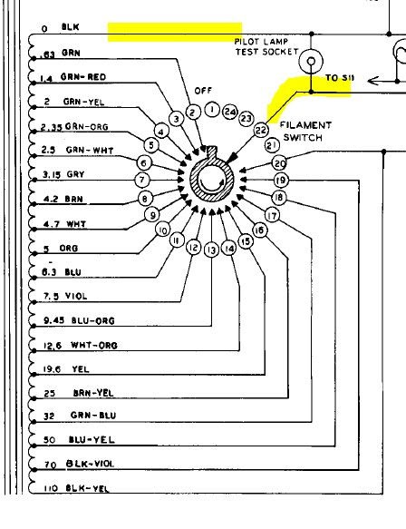
Heater switch
The heater switch works in a similar way in order to select which output tap to use to select a voltage for the heater.
I've highlighted in yellow the outputs. Again this switch allows turning the heater off separately. If we use a power supply for the heater, we don't need this. If you don't have a separate supply, and are using filament transformers, you'll just need to switch between them as appropriate.
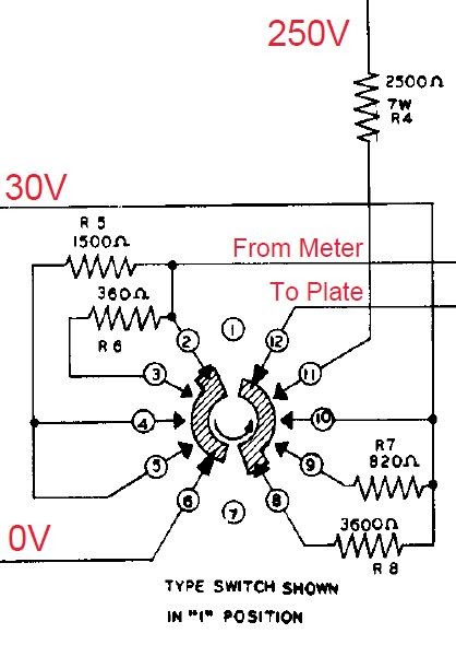
Type switch
The type rotary switch has two sides.
The right side as shown in schematics selects the plate resistor and voltage (B+).
Plate connection for type:
3600 ohm to 30V
820 ohm to 30V
0 ohm to 30V
2500 ohm to 100V
The left side as shown in schematics selects the series resistor connected to the meter.
Meter series resistor for type:
0 ohm
360 ohm
1500 ohm
1500 ohm
Other elements
The other elements, including the neon and all the switches are not as important to analyze as they simply connect the relevant points for each test.
Minor notes:
The neon has current limiting resistors, and is used as a low current indicator. A switch is used to adjust the tube resistance threshold to distinguish between as "short" and leakage.
The long bank of switches serve to select what each pin of the tube is connected to. Either 0 (bottom), selected filament voltage (middle), or high test voltage (top). One switch per pin.
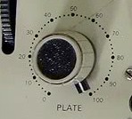
The Plate control pot adjusts the scale of the meter. This, along with the charts, are the "secret sauce".
Secret Sauce
Conveniently, the charts are something that Heathkit kept up to date over the years. They had a subscription service so users could regularly get the latest.
Here's a copy from 1979, which I'd have to guess is one of the latest, but certainly will do for most purposes.
For the plate control pot, we know from the schematics it is 200 ohms. Based on other sources, this is wire wound. To convert the setting to a position we need the labeling on the front panel. Helpfully there are plenty of clear pictures which show this to simply be 0-100.
Likewise for the meter, we can see the range in the picture, and knowing the meter is 0-1mA(some clearer pictures and other sources), we know that mid point is 0.5mA, and can estimate the threshold for good by angle/percentage.
And that should be everything we need. But there is one more important bit, the meter resistance. I have been unable to find that spec on these meters in all the sources I've looked. If we knew the value of the diode forward voltage we could figure it out based on the "set line" mode, but I can't find that number either. We'll come back to this based on a little testing later on. (and this will depend on your meter is as well)
 Quinn
Quinn