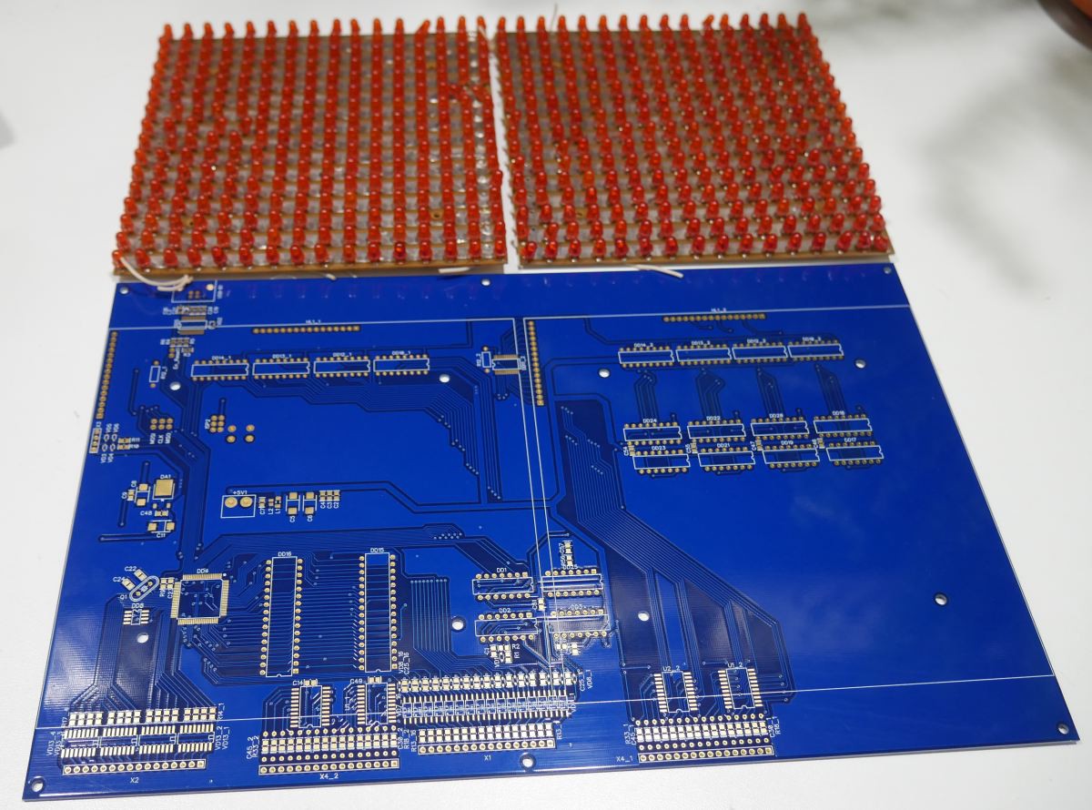
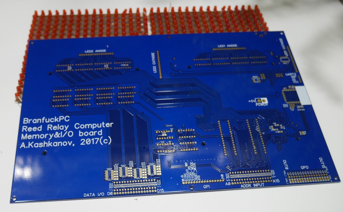
Received memory board.. Oh man.. It look so cool. Need to start parts soldering. There are 16x16 led panels for this board. dimensions 300x200 mm.


Published an article about this board on Russian geek site geektimes.ru on the first of April. That was very good idea - My article was very popular this day.
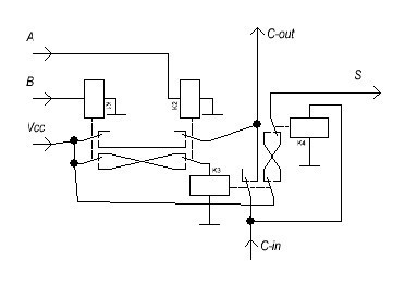
And as a result - someone in comments gave me advice how to optimize adder schematic and reduce relays for it from 256 to just 112! It's the whole block! Carry chain - is very good idea for this project.
Here is schematic:
There is an error near K4 - contacts are reversely connected. So instead of 32 modules with 3 different types (ADD+C, 2AND/2OR, 5AND) I just need 32 modules with one type! 2AND/2XOR
Will create schematic and routing for this module in nearest future.
 Artem Kashkanov
Discussions
Become a Hackaday.io Member
Create an account to leave a comment. Already have an account? Log In.
The circuit doesn't show how to perform subtraction, another XOR is missing...
Are you sure? yes | no
Substraction works as before - as addition in two's complement mode.
We send to input B inverted (with sign extention) value. inverted B is already stored in memory (In brainfuck I can add or sub only constant values on input B). And Send log.1 to Carry0 signal.
As the result we have: OUT=A+(inv(-B))+1
Are you sure? yes | no
Wow I'm impressed again :-D
For the adder : yes it's a sort of grey area because, unlike with transistors or CMOS, there are different approaches. More on this there http://6502.org/users/dieter/a3/a3_2.htm
But I must adapt for my CCPBRL circuits...
BTW do you know you can do a xor with a simple relay ? ;-) but then you have to work with "Vcc-GND" signals and not "Vcc-open" signals.
Are you sure? yes | no
I already experimented with vcc-gnd signals before - it's more dangerous, and I don't want to use this approach.
Thanks for the page - think I can do more improvements for my adder without performance regression :)
Are you sure? yes | no
I'm looking forward to reading the next logs :-D
Are you sure? yes | no