Sergio Ghirardelli
-
Module failure test
07/12/2022 at 20:38 • 0 commentsWhat happens when one of the sensor modules fails?
The answer is in the following video ... -
60 modules communication test
07/07/2022 at 14:46 • 0 commentsWe all know that theory is often not reflected in practice.
Could I submit a sensor network project, claiming a network of 60 sensors without being sure it worked?
No! I had to be sure, so I decided to test if my theoretical calculation was correct.
The following video shows the tests carried out.
Why 60 modules limit?
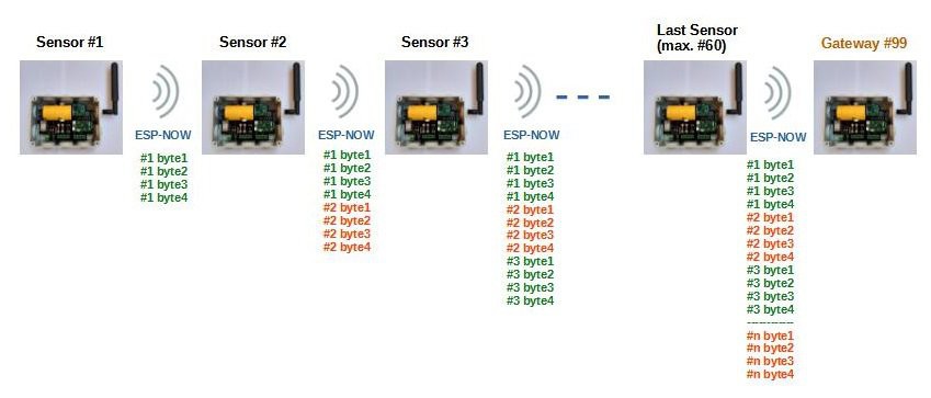
Green detect wireless sensor network uses ESP-NOW protocol.
The first ESP-NOW technology limitation is that the total number of peer devices should be less than 20.
How did I exceed this limit?
I simply created a chain network, where each device communicates with 2 other devices the one from which it receives the packets and the one to which to send the processed packets.
![]()
Basically I created many small networks, exceeding the limit of 20 devices.
Why can Green Detect network include a maximum of 60 devices?
Because the ESP-NOW technology has another limitation: up to 250-byte payload can be carried.
And since I have foreseen 4 bytes of transmission per sensor, I can use a maximum of 60 sensors (60x4 = 240 bytes)
-
Solar charger circuit
06/30/2022 at 12:41 • 0 commentsWhen I thought about the Green Detect project, I immediately had in mind the outdoor use and the total energy autonomy of the sensors, with solar panel charging and energy storage,
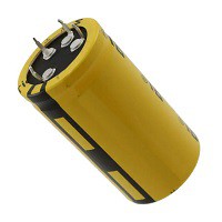
The challenge I immediately thought about was to make the project significantly more eco-compatible by using a supercapacitor.
I made the first tests with low cost supercapacitors, with poor results.
So I tried with a quality product at a reasonable price: Eaton cod.XV3560-2R7407-R
![]()
For the choice of the supercap, I used the Eaton calculation tool:
https://www.eaton.com/it/it-it/products/electronic-components/supercapacitor-calculator.html
I was clearly aware that it would be the practical test to tell me if the choice was right!
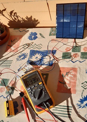
The first breadboard tests were encouraging, so I started working on the solar charging circuit.
I needed a simple, inexpensive circuit able to get even a few mA to the supercap (for example on cloudy days).
The charge of the supercap must follow a fundamental rule: the charge voltage must not bring the supercap to a voltage higher than 2.75 V.
![]()
The end-of-charge voltage of the supercapacitor is the same as that of 2 Ni-Mh batteries in series: this analogy led me to think of a solution that would leave a door open for “plan B”: use 2 NiMh batteries instead of the supercap in case this fails to power the sensor.
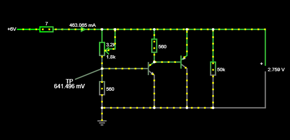
After a series of tests I thought about using a current shunt regulator circuit.
I simulated the circuit with online Falstad simulator:
![]()
This circuit keeps the voltage constant by draining the current to GND.
The voltage is established by appropriately dimensioning the voltage divider resistances at the base of the NPN transistor.
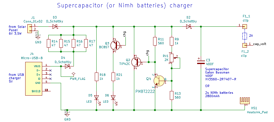
With a few additions and improvements, the charging circuit is this:
![]()
I added schottky diodes to block reverse currents and the possibility to charge from USB.
The only effect to consider is the temperature on the body of the power transistor Q2 at the end of the charge, when all the current supplied by the 3.5W solar panel (max 520 mA) is drained to GND by Q2.
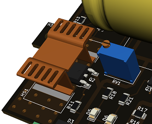
To dissipate the heat, I designed a large GND plane at the bottom side of the PCB, also I added a heatsink on transistor Q2.
![]()
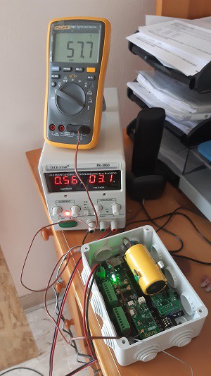
The result is good: the temperature on the transistor body does not exceed 60 °!!!
![]()
I love simplicity!
Green Detect
Wireless Sensor Network Platform (WSN) , for enviromental monitoring