-
26-Pin Connector
07/20/2022 at 14:46 • 0 commentsFor those of you that just want to run the DSKY using the internal software simulator, congratulations! Your model is complete. For those of you that want to connect to an external AGC, you will need to wire up the 26-pin connector.
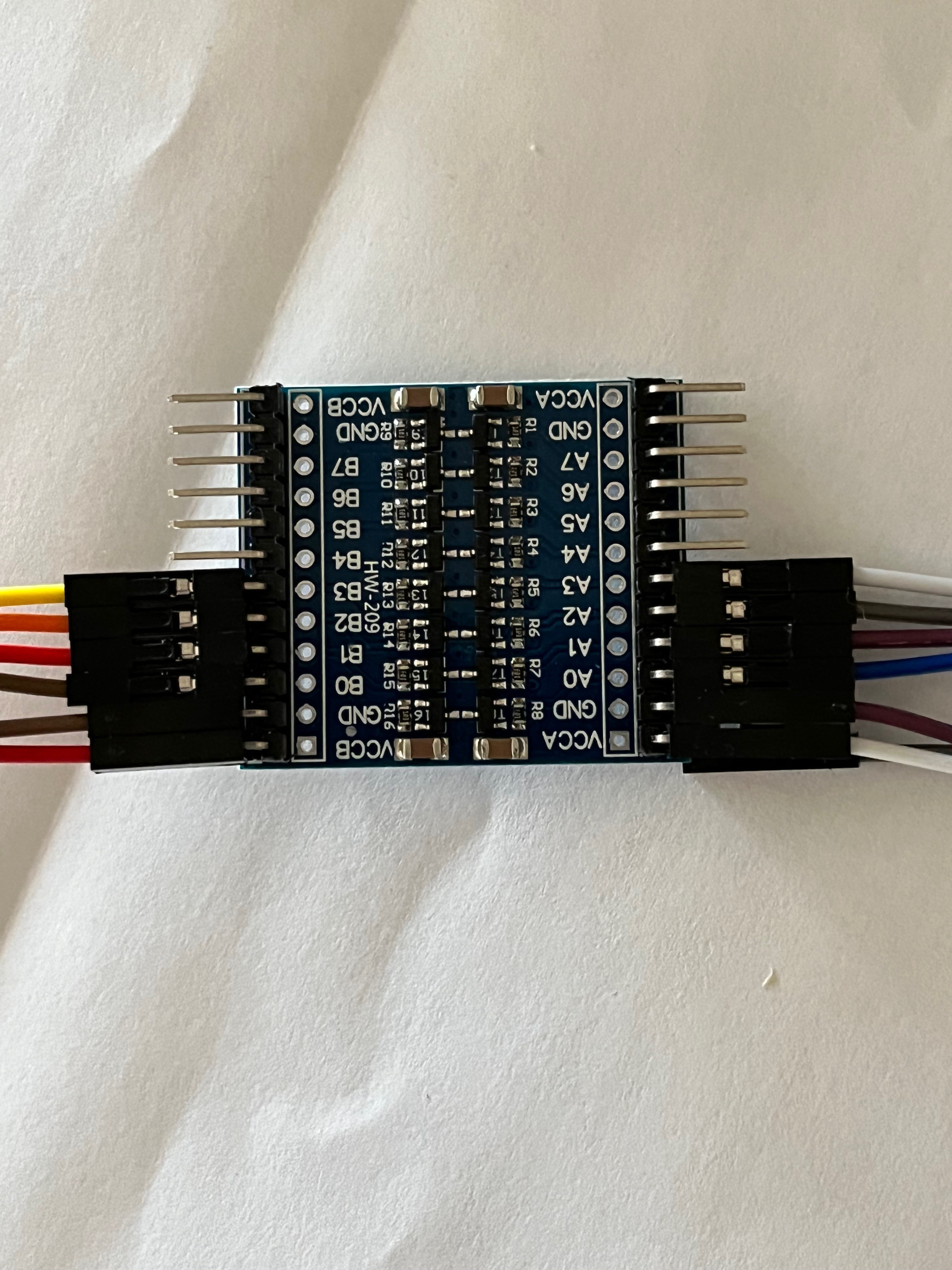
The external AGC I am working on is comprised of TTL chips and therefore uses 0-5v voltage levels. The DSKY uses a Raspberry Pi that is CMOS based and uses 0-3.3v levels. This requires voltage level conversion on the lines. There are many solutions from making your own from discrete components to using fancy chips. The Channel bus lines are bidirectional. I chose a simple yet clean solution, pre-manufactured boards using MOSFETs. You can pick up a bag of five 8-line converters for under $10. Two are required for the Channel bus and two are required for the control lines.
![]()
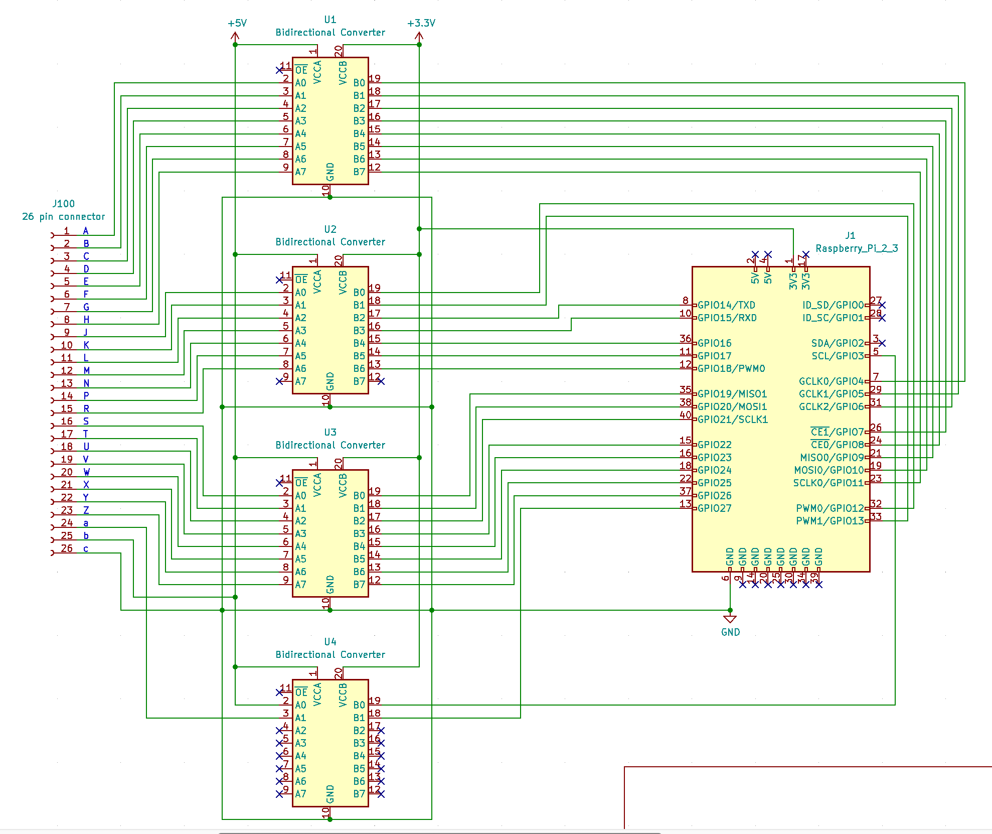
KiCad did not have a symbol for this level converter so I chose a device that is essentially the same except it has an output enable pin that I didn't use.
![]()
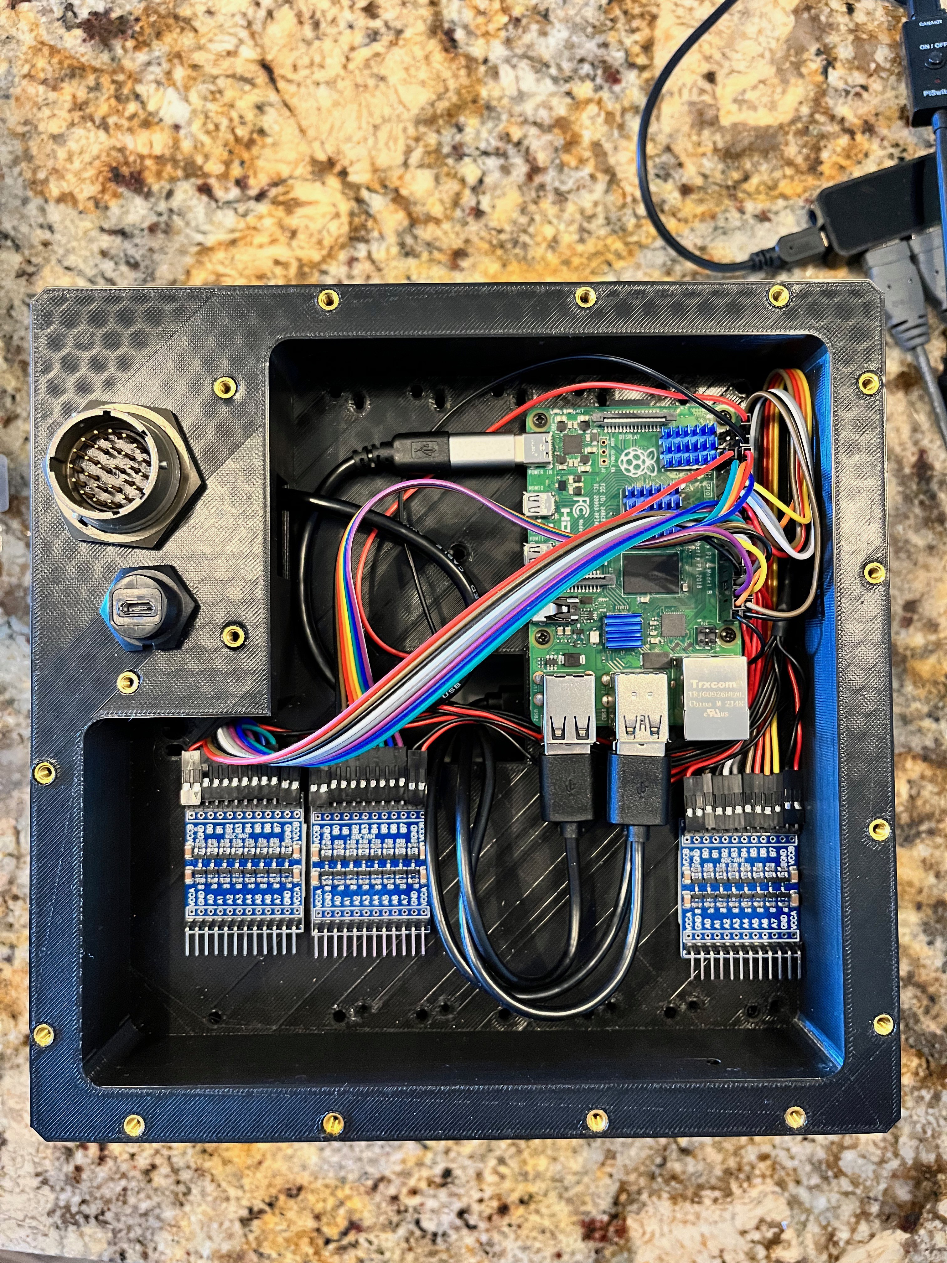
Here are the level converters installed with double sided foam tape. There were no mounting holes, but a smooth back.
![]()
-
Run as a Service
07/17/2022 at 21:05 • 0 commentsTo make this a stand-alone DSKY you need to run the two processes (DSKY and AGC simulator) as services. This is fairly simple on a UNIX variant, in this case I am using Rasbian, the default OS for a Raspberry Pi. Start by running as root and cd to /etc/systemd/system. Now copy the two files I have out on Git hub named AGC.service and DSKY.service. To auto run the AGC you will also need a file named command.file. I placed this file in /home/pi/virtualagc/yaAGC but you can place it just about anywhere and name it almost anything. The important thing is that it contains a single line with the text "run". Here is the AGC.service text.
After=multi-user.target
[Service]
Type=idle
WorkingDiretory=/home/pi/virttualagc/yaAGC
ExecStart=/home/pi/virtualagc/yaAGC/yaAGC ../Luminary131/Luminary131.bin --command=/home/pi/virtualagc/yaAGC/command.file
[Install]
WantedBy=multi-user.target
The description is simply a name you give this service.
Now that you have the two services in place, you need to reload the daemon.
> systemctl daemon-reload
Now enable both services.
> systemctl enable AGC.service
> systemctl enable DSKY.service
Now every time you reboot the two services will start and the DSKY will fire up and you can start using it right away. If you don't want to reboot you can start them by using the following commands.
> systemctl start AGC.service
> systemctl start DSKY.service
You can also stop the services in a similar way.
> systemctl stop DSKY.service
> systemctl stop AGC.service
-
Model Polish
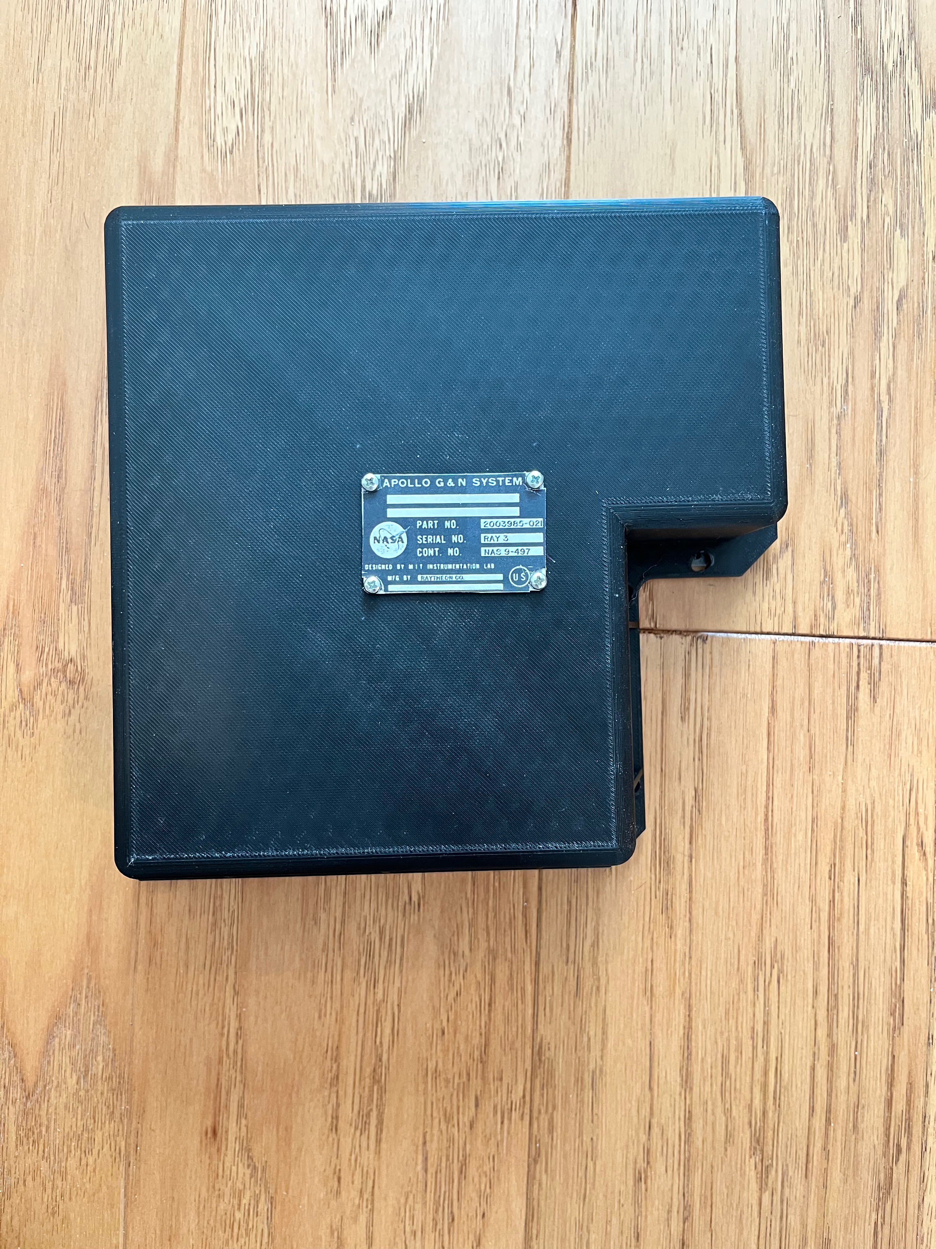
07/15/2022 at 21:16 • 0 commentsI added a nameplate to the back, just to make the model more realistic. There is a thin part named NamePlate that I 3D printed. There is also a file named NamePlate to print on thick card stock. Glue the paper name plate to the 3D name plate. I colored the side of this assembly with silver paint and then glued this to the back of the DSKY. To make it even more realistic, I dug up four small screws with rounded heads and cut the heads off and glued them to the four corners of the name plate.
![]()
-
Software Improvements
07/15/2022 at 15:18 • 0 commentsThe first improvement is to simplify the indicator commands between the Pi and the Arduino. Instead of splitting out the channel 11 and channel 10, relay word 12 writes into separate commands on the Pi, I modified the interface to send a single command each to the Arduino and let the Arduino sort it out. Here is the following new command structure. The Display and Other indicators command send the command followed by a number. Ex: "3 20" is used to light the ALT and PROG indicators.
0 Noop
1 Reset to power on state
2 Identify
3 Display Indicators:
NO ATT : bit 0
GIMBAL LOCK : bit 1
PROG : bit 2
TRACKER : bit 3
ALT : bit 4
VEL : bit 5
4 Other Indicators:
UPLINK ACTY : bit 0
KEY REL : bit 1
OPR ERR : bit 2
TEMP : bit 3
STBY : bit 4
RESTART : bit 5
I always seem to do my best thinking at night when I am asleep. Woke up this morning and realized that checking for a clock pulse on the clock line is not a good way to check for the presence of hardware since the hardware can be in debug mode and you can stop the clock, step the clock or not even have the hardware running yet. A better way to do this is to use one of the unused hardware pins as a H/W Present pin. I will configure that pin on the Raspberry Pi with the internal pull-up resistor. If the hardware is connected, it will pull that pin low signaling the presence of hardware. I have also decided to have my hardware simulator run external to the DSKY, thereby simulating the hardware through its 26 pin connector. This means I will modify the way the Raspberry Pi starts up. By default there will be no arg, an arg will only be used if you wish to run the internal test. The software will check the H/W Present pin and if low take inputs from the 26 pin connector, if high it will connect to the internal software simulator.
The interface to the Display Arduino has been modified to simplify this interface as well, pushing the decode logic to the Arduino. Here is the new command structure.
0 Noop
1 Reset to power on state
2 Identify
3 Display command
4 COMP ACTY indicator
5 Flash Verb/Noun
The display command takes the 15-bit Channel 10 values, all except relay word = 12 which is routed to the Indicator Arduino.
I also simplified the program interface. If no argument is supplied, the internal software simulator is used. If "--TEST" is supplied then the internal test is executed. In the near future the software will check one of the GPIO pins for a H/W Present signal which will cause the code to interface with the 26-pin connector. Either the hardware AGC or hardware simulator will connect to this pin.
-
LCD Version 2
07/13/2022 at 17:32 • 1 commentNow that I have Ron's simulator up and running, I realize the SPI interface to the LCD is too slow. The interface is too slow to get the Verb/Noun flashing to work. My next step is to get the 8-bit interface working between the LCDs and the Arduinos. I will now take one of the LCDs out, solder up the 8-bit connector and breadboard that to see how much faster it runs...
And the results are in! The 8-bit is not any faster and in some cases slower than the SPI. Both interface libraries have graphics test programs but they are a bit different. I took the 8-bit test program and modified it to run using SPI and performed a run-off using the same code for both interfaces. Here are the results. Times are in seconds.
Test SPI 8-bit Screen Fill 3.097048 2,758792 Text 0.168432 0.356892 Lines 2.737540 6.946940 Hor/Vert Lines 0.260936 0.278024 Rectangle(outline) 0.147964 0.172116 Rectangle(filled) 7.550376 7.670884 Circles(outline) 0.988020 1.851536 Circles(filled) 1.144472 2.950412 Triangle(outline) 0.531856 1.316972 Triangle(filled) 2.996452 3.605184 Roundtangle(outline) 0.421524 0.920348 Roundtangle(filled) 7.562608 7.917336 So despite the AdaFruit documentation claiming the SPI interface is 2 to 4 times slower than the 8-bit, I don't believe it. Maybe this is because the Arduino Nano Every uses a newer ATMega4809 processor versus the older ATMega328P processor. I had assumed the SPI interface pushing bits across the interface would be significantly slower than pushing 8-bits at a time.
The numbers don't lie so I will stick with the Nanos and look at improving the code performance.
-
Software
07/05/2022 at 19:18 • 0 commentsI have tested the three Arduino's software with test code on the Raspberry Pi. The Arduino code is out on my GitHub website. https://github.com/bglasford1
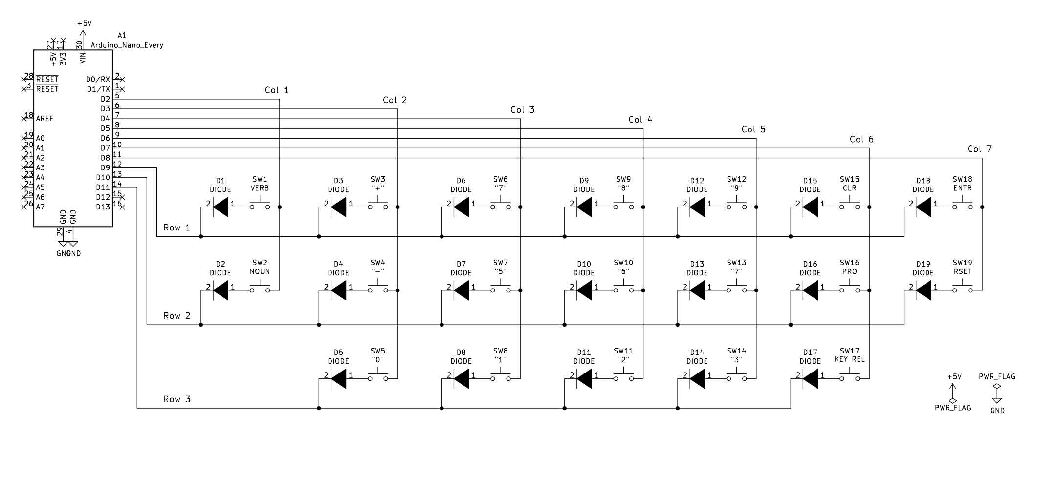
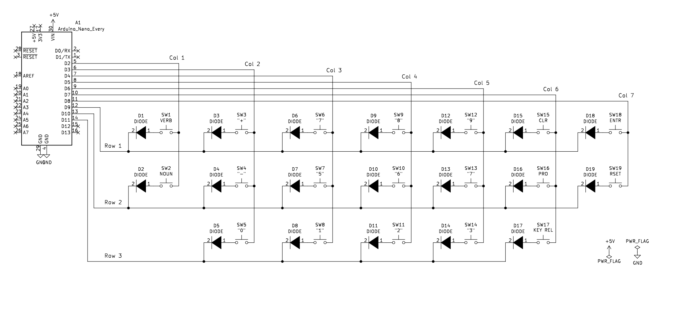
There are 3 Arduinos: Display, Indicators and Keyboard. The display and indicators wait for a command from the Raspberry Pi, execute the command and then wait for another command. The first command for all three is an Identify command in which they respond with who they are. This allows me to map the port to purpose as I am not guaranteed each Arduino will connect to a specific port name. The Keyboard periodically scans the matrix waiting for a key press. When a key is pressed it sends a notification to the Raspberry Pi. I used a matrix scheme versus connecting each switch to a digital input because the Arduino has 13 digital input pins and I need 19. The switches are arranged in a 3x7 configuration. This requires 10 pins. I could have configured them into a 4x5 configuration that would have used one less pin but I kept the matrix simple and logical, keeping the keys as they relate to the matrix in their physical configuration.
An initial version of Java is out there on GitHub for the Raspberry Pi. The software has a completely functioning Arduino interface. The interface to the AGC has been fleshed out but not tested. In its place is a test class that runs the Arduinos through their paces.
The DSKY code interfaces with either an internal simulated software AGC or via the 26-pin connector. The 26-pin connector is used to connect a hardware AGC implementation or a hardware simulator. There is also an internal test program which can be executed by providing an argument of "--TEST".
I am now working on getting Ron's simulator working with the DSKY. His simulator has a separate DSKY module with a software protocol based on the real interface. The real interface has a 15-bit Channel bus and various control lines directing where the data should be routed based on channel number. I view it as memory mapped I/O. The DSKY deals with five channels (as defined by NASA).
Channel 10: AGC to DSKY: Used to send display updates 2 characters at a time plus indicators.
Channel 11: AGC to DSKY: Used to send indicator status. Not sure why 1/2 are here and 1/2 in ch10.
Channel 13: AGC to DSKY: Test lights and STBY indicator. (Ron put this into his fictitious ch163.
Channel 15/16: DSKY to AGC: Sends one key code at a time when a key is pressed.
Channel 32: DSKY to AGC: Used to send a PRO key press.
Channels 13 and 32 have other functions as well that the DSKY doesn't care about. Note that Channels 15 & 16 are the same format. The Command Module had two DSKYs, hence two channels for key presses. I am implementing DSKY #1, therefore I only use ch15.
Ron's interface combines the 15 bits of the channel register along with a 7-bit channel number plus a "u" and "t" code that are set to zero for the DSKY. He packs this into four bytes with the first two MSBs of each byte used to define the sequence of four bytes. The following is the format of the four bytes (both directions). "p" denotes channel number and "d" denotes the channel data.
00utpppp 01pppddd 10dddddd 11dddddd
The details of all this can be found at https://www.ibiblio.org/apollo/developer.html or at my GitHub site in the AGCBlockIIComputer wiki pages.
The code using Ron's simulator is now working and code updates have been made to GitHub.
Here is how to load, compile and run Ron's simulator. The instructions on his site are a bit old and the version of wxWidgets has changed.
1) Install these packages: sudo apt-get install wx3.0-headers libwxgtk3.0-gtk3-dev libwxgtk3.0-gtk-0v5 libncurses5-dev liballegro4-dev git
2) Load his code: git clone https://github.com/virtualagc/virtualagc
3) cd virtualagc
4) make install or make clean install
This takes quite a while on a little Pi to compile all this. Once it is compiled, cd into the yaAGC directory and run the simulator. This command runs the code for the Apollo 11 LEM. You can run other versions as well.
> ./yaAGC ../Luminary131/Luminary131.bin
The simulator will start and give you a prompt of (agc). Type run to start the simulation.
Here is how to load, compile and run my DSKY code. The code is java. I strongly suggest you use an IDE. I personally use the free version of IntelliJ Idea but Eclipse is just as good. Load the software into the IDE and set it up to create a jar file. Copy the jar file over to the Raspberry Pi and execute it with this command.
> java -jar DSKY.jar --AGC-SWSIM
The Arduinos will have already displayed the initial state on the LCDs. Running the DSKY simulator will reset the Arduinos so the displays will redraw and you are ready to go. Start typing in commands. I would suggest starting with the lam test: V35E. What is this? It is NASA shorthand for the following keys: Verb, 3, 5, Enter. You should see the 3 and then the 5 being displayed under Verb. When you hit enter all the indicators light up and all the digits are set to "8". The verb and noun values flash along with the KEY REL and OPR ERR indicators.
-
Painting Model
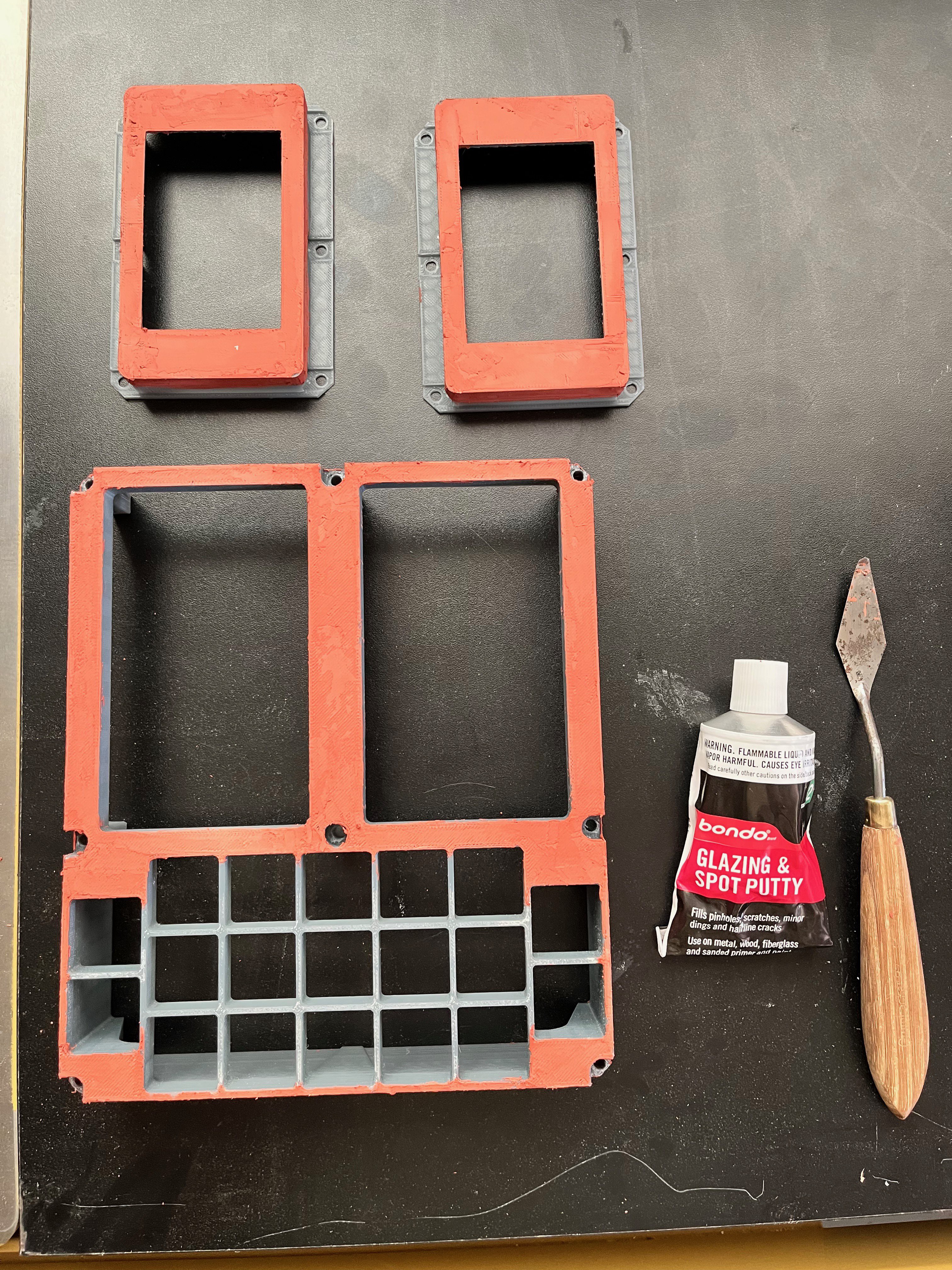
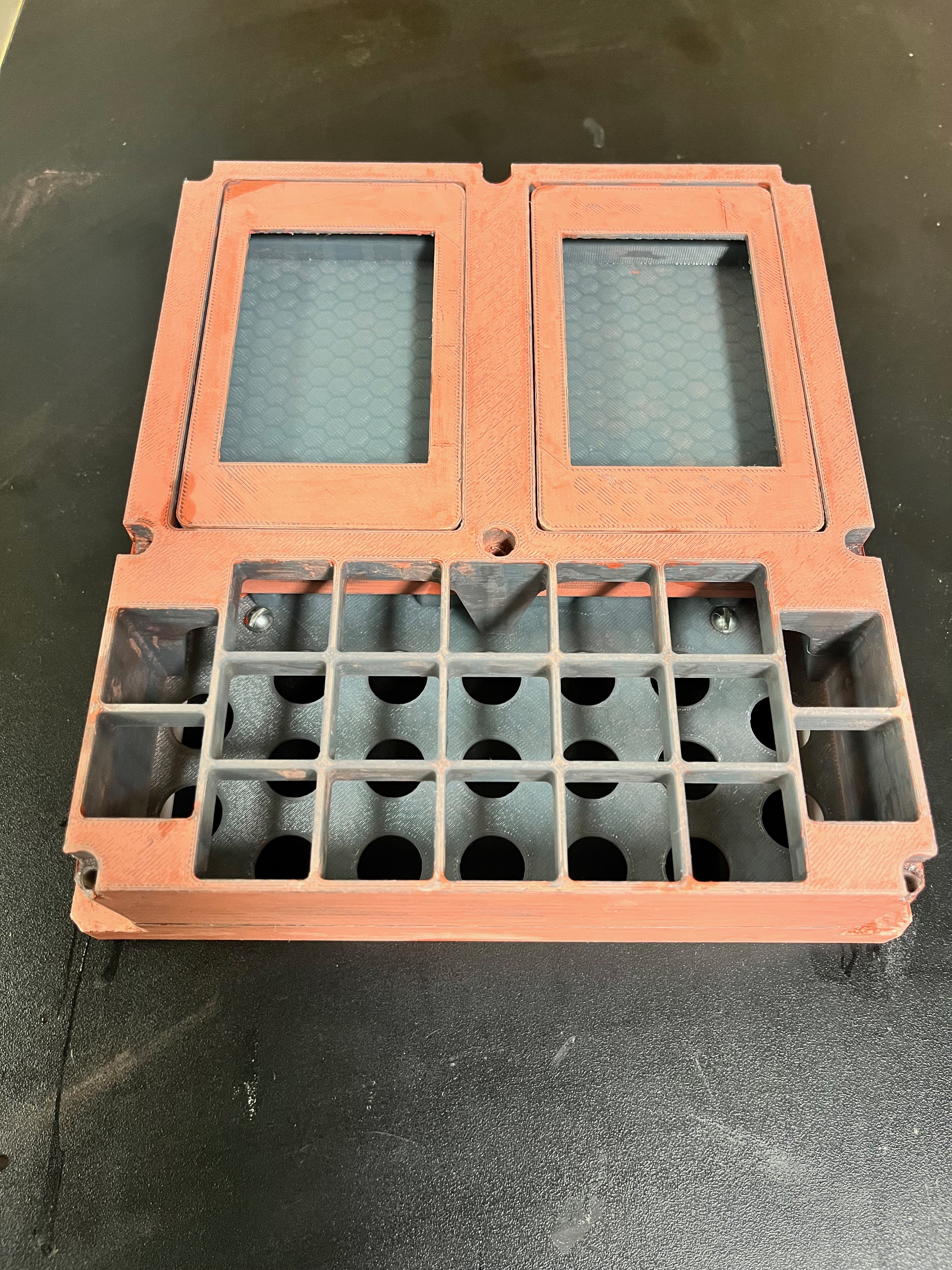
07/01/2022 at 22:48 • 0 commentsThis model needs to be painted to look as realistic as possible. I am using Bondo to smooth out the visible surfaces when the model is assembled. Once the Bondo surfaces are sanded I will paint all surfaces with a gap filling primer, sand again and then paint the pieces with as realistic a paint as I can find.
I have started the Bondo process. Here is a picture of the initial Bondo application of some of the pieces.
![]()
Once it dries overnight I sand it down to 220 grit and clean it up.
![]()
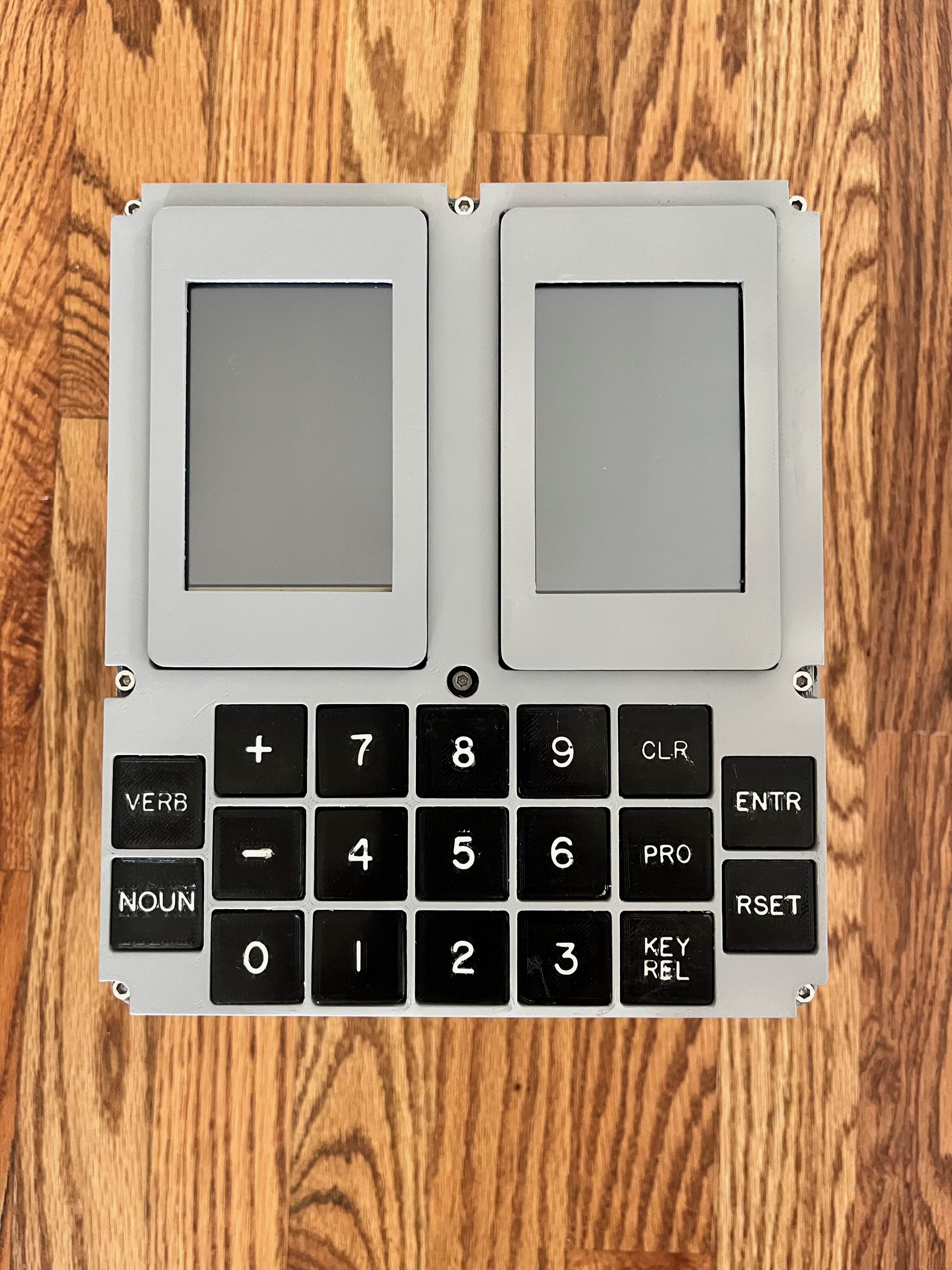
The paint arrived and I sprayed it. You will notice that I enlarged the font of the keys and reprinted them. I'm getting better at mixing the dye into the epoxy and filling in the characters.
The case is complete! As is the keyboard.
![]()
-
Switches/Keyboard
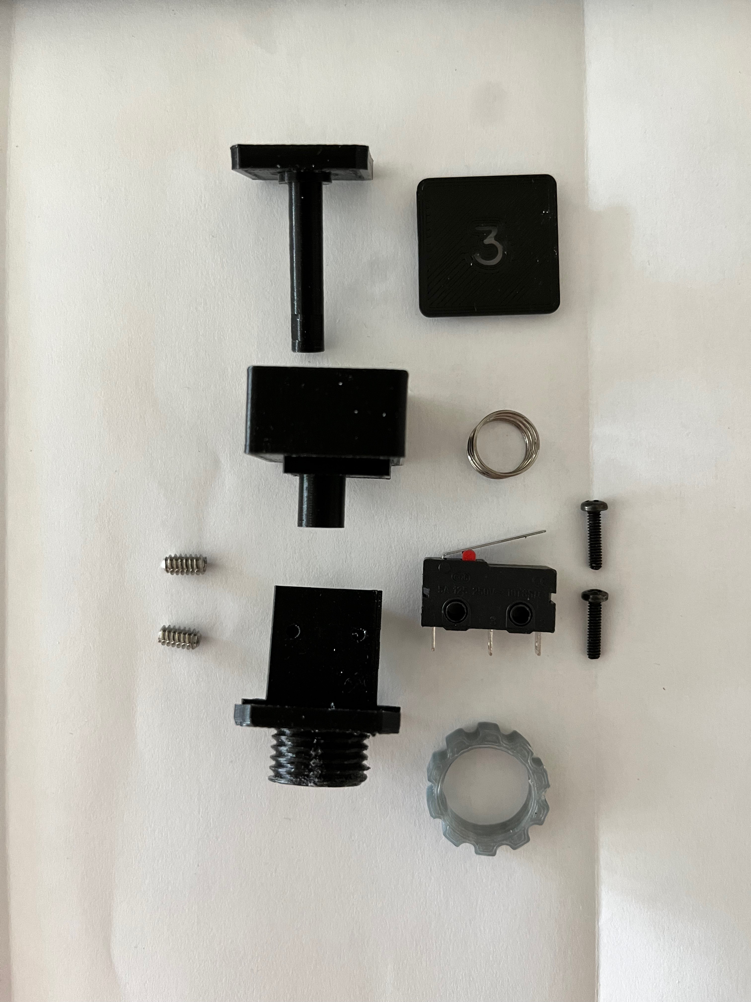
06/27/2022 at 14:17 • 0 commentsThe switches are the hardest to get right. Fortunately I had a starting point thanks to M. DeSilva and his DSKY replica. From what I can gather, he put the spring inside the housing. I could not find a spring that would fit so I placed the spring on the outside. I also used screws to secure the microswitch instead of force fitting them onto plastic posts. I used 3mm white LEDs. I modified the key caps using a Gorton font I found at https://github.com/dakotafelder/open-gorton. I had to convert the .otf file to a .ttf file so it would work with Fusion 360. I used a small amount of white dye added to epoxy to fill in the back side of the key caps to make the letters white and to allow light to show through. Here are pictures of the switch pieces and three views of the switch.
![]()
![]()
![]()
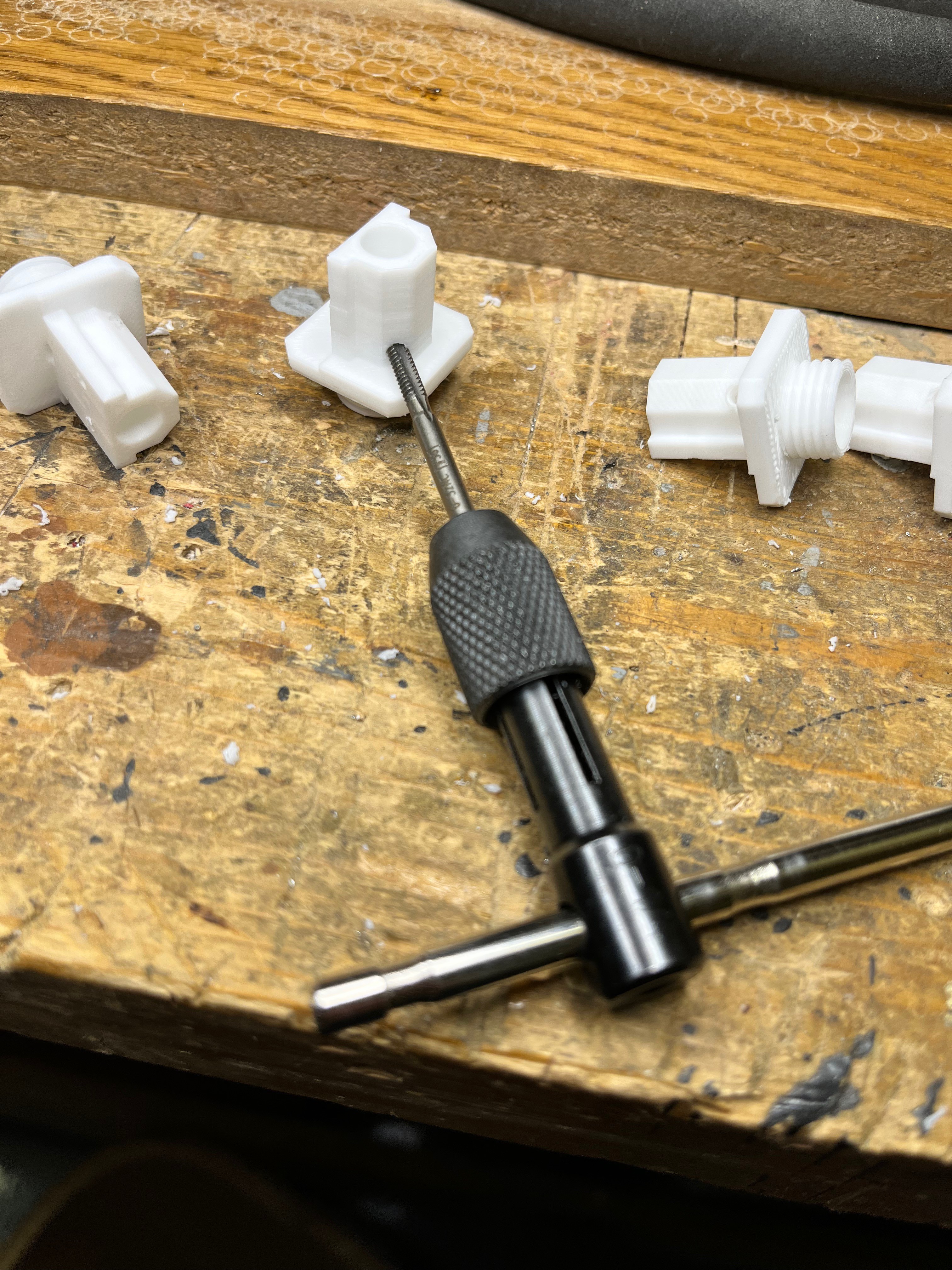
![]() For the large nut that holds the switch assembly down I created the nut in the CAD system and then scaled it up, something like 10%, I don't remember the exact value. Without the scale up the nut was too tight a fit. To install the set screws, instead of scaling up the threads I chose to simply tap the hole for a perfect fit. I first drilled each hole to 3/32" and then tapped them with a 6-32 tap. For the smaller holes that hold down the microswitch I did not have a 2-56 tap in my set so I drilled those holes with a 5/64" bit and simply installed the screws. The plastic is pliable enough that the screw made its own threads.
For the large nut that holds the switch assembly down I created the nut in the CAD system and then scaled it up, something like 10%, I don't remember the exact value. Without the scale up the nut was too tight a fit. To install the set screws, instead of scaling up the threads I chose to simply tap the hole for a perfect fit. I first drilled each hole to 3/32" and then tapped them with a 6-32 tap. For the smaller holes that hold down the microswitch I did not have a 2-56 tap in my set so I drilled those holes with a 5/64" bit and simply installed the screws. The plastic is pliable enough that the screw made its own threads.![]()
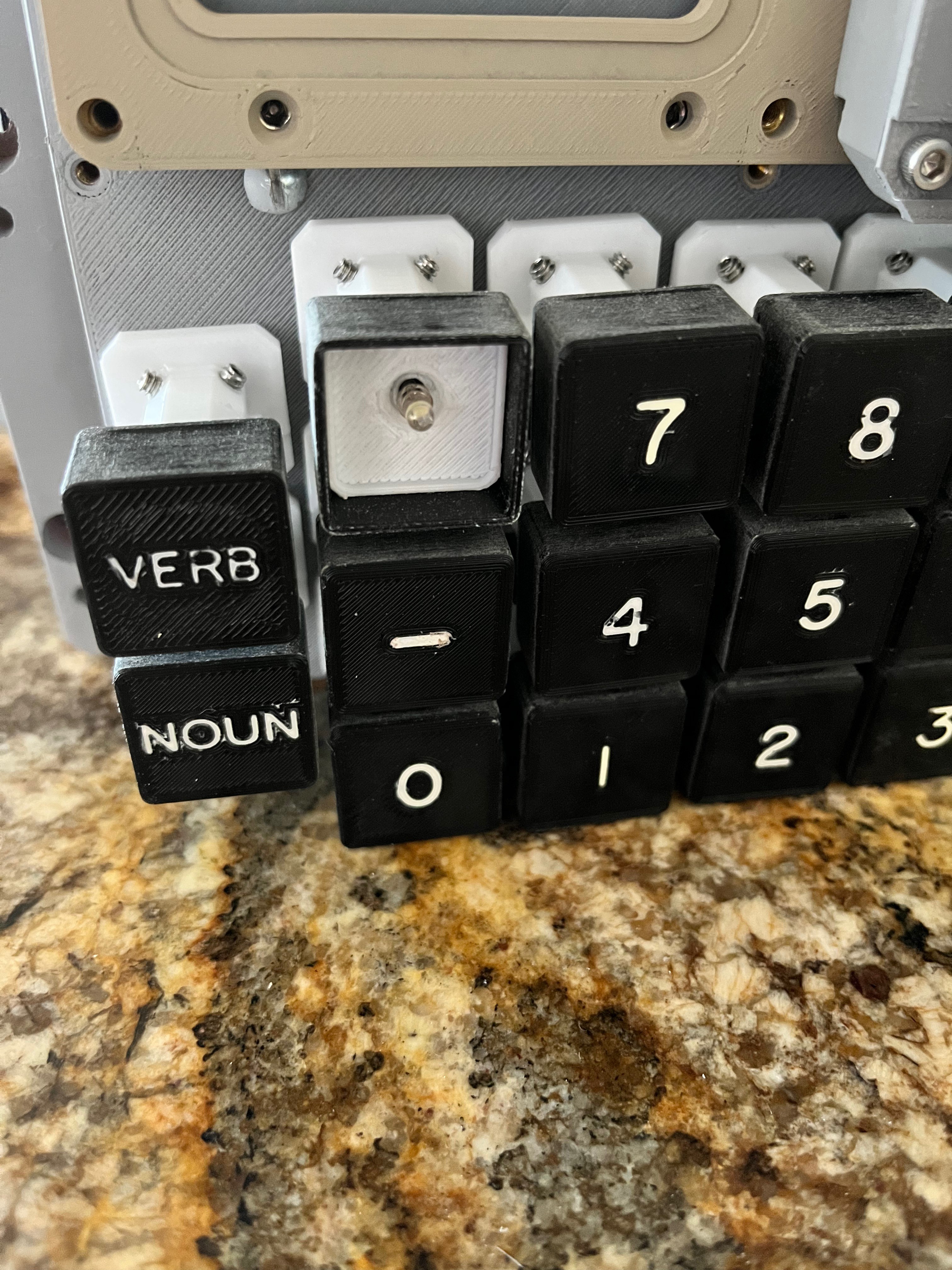
The keys are now mechanically working. I had to sand the surfaces that grate against each other to eliminate that strange rasping sound. The set screws had to be adjusted so the keys are level with the front cover. I'm not happy with the way the key covers came out, all except the + and -, those are OK. I changed the font to Gorton Heavy and scaled the size up.
The keyboard wiring was simple enough. I chose to go with a matrix solution even though there is enough input pins on the Arduino to connect each switch to its own pin. Here is a schematic of the keyboard.
![]()
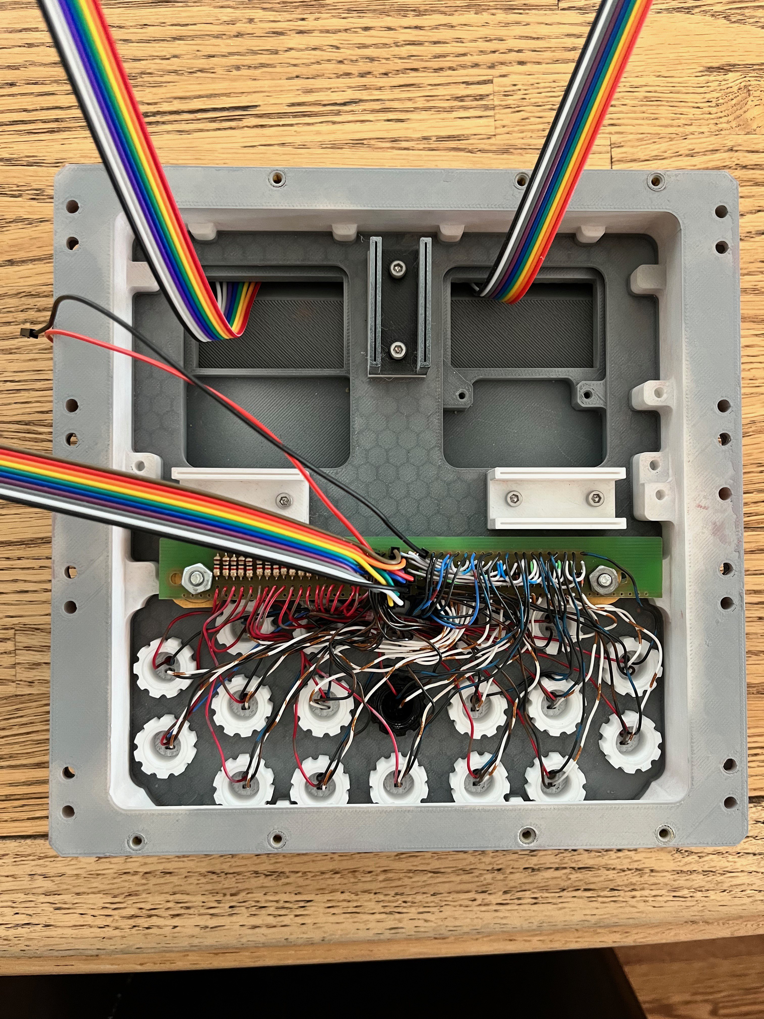
And here is a picture of the back side of the keyboard. I not only laid in 19 diodes, there is also 19 resistors to reduce the brightness of the LEDs.
![]()
I forgot to mention the LEDs. I used the smaller 3mm white LEDs. Solder two wires to the leads. You only need to shrink wrap one of the leads. The wires get pushed through the center of the switch as in the picture below.
![]()
-
Hardware
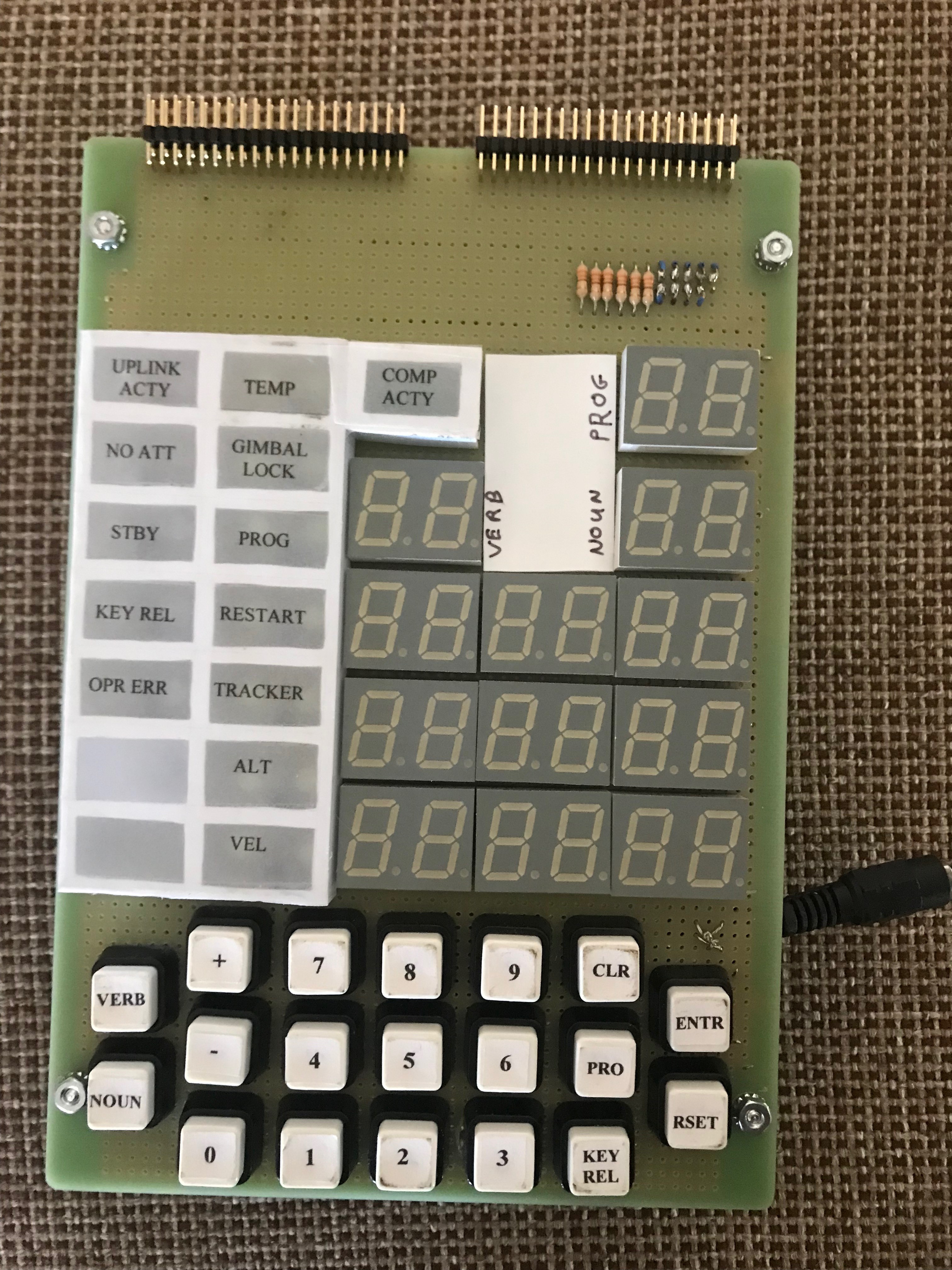
06/26/2022 at 17:01 • 0 commentsHere is a picture of my AGC DSKY from the AGC project. It is not the prettiest thing, but it works.
![]()
From this effort I decided this would be a much better model if I used a pair of LCD displays instead of the 7-segment LCDs and backlit indicators. Besides, the 7-segment LCDs cannot display a plus.
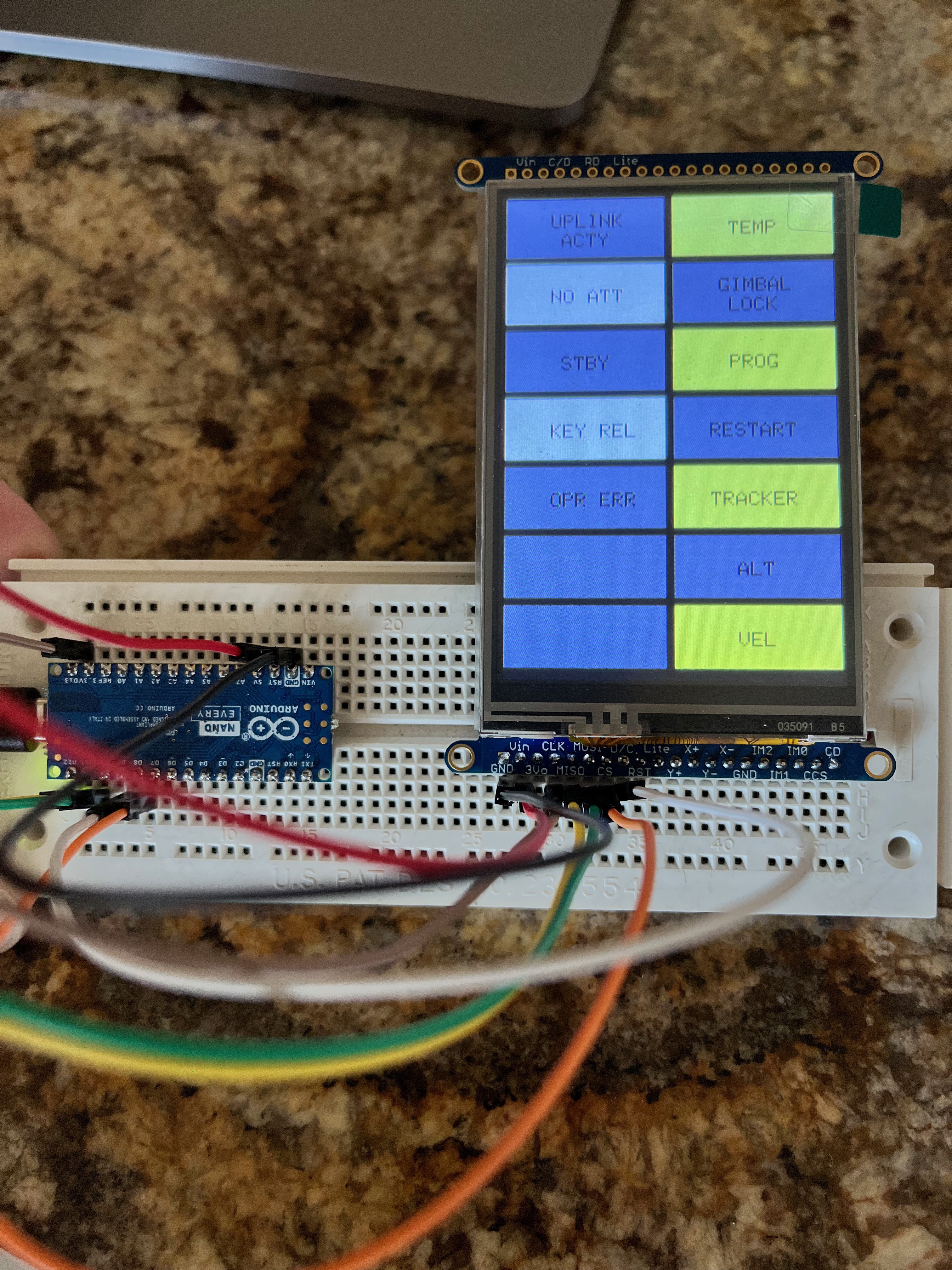
Here is the first cut at the indicators panel, much better looking than the display above. I need to work on the colors of the indicators. The display is from Adafruit, a 3.5" LCD display.
![]()
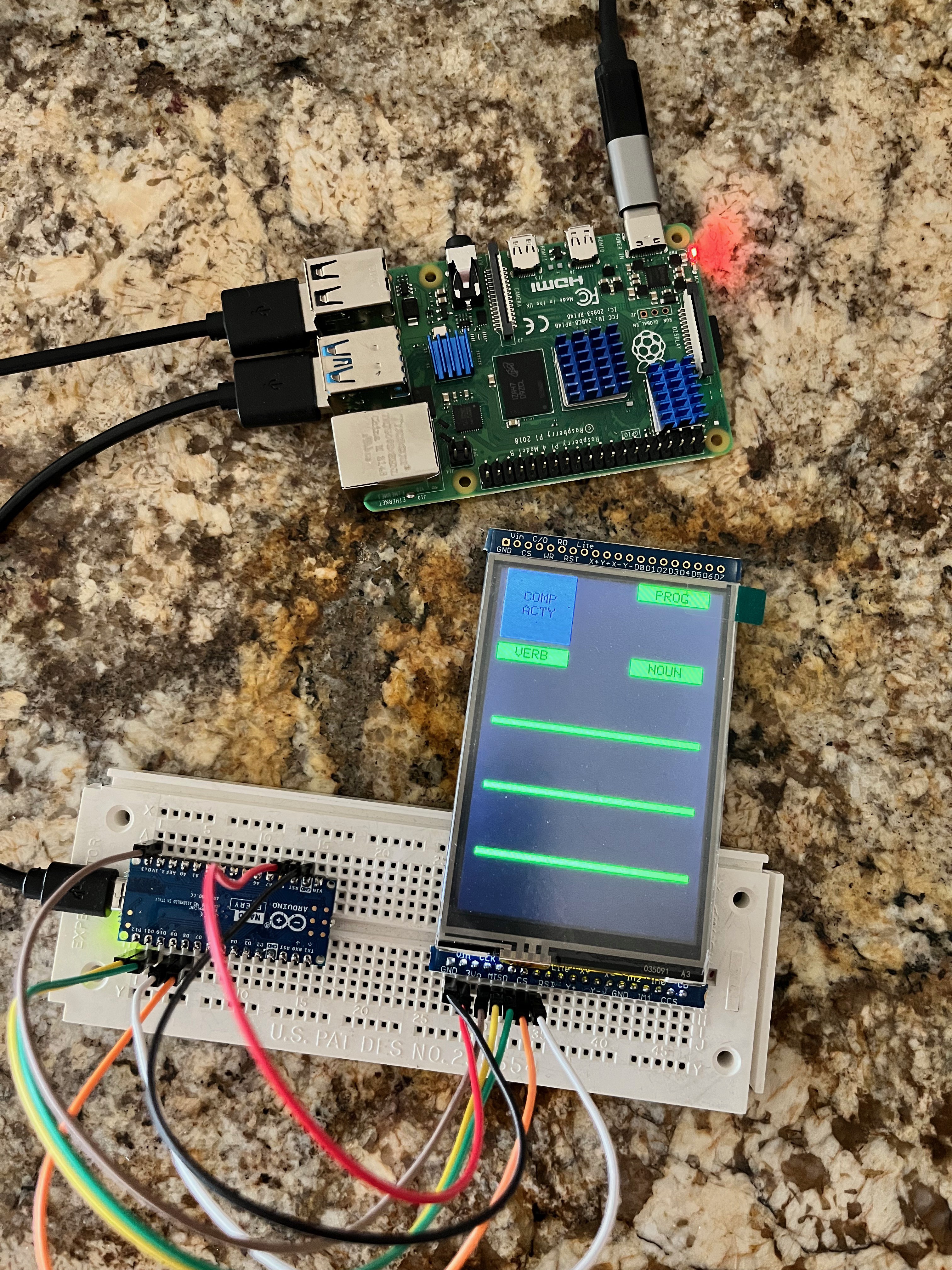
Here are the display LCD under test. I connect them using SPI and created a simple protocol to identify each one upon initialization.
![]()
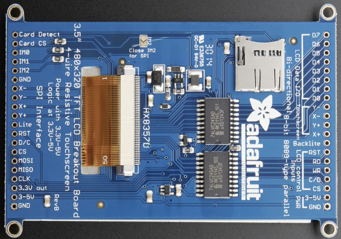
The LCD displays both connect to their respective Arduino in the same way using SPI. There is an option of using 8-bit mode as well, however that mode is seriously more complicated so for now I have gone with SPI mode. It is 2 to 4 times slower. I will have see once everything gets wired up and working if that is acceptable. For SPI mode you have to solder the IM2 jumper closed. Here are the connections between the LCD and the Arduino.
Arduino
PinLCD
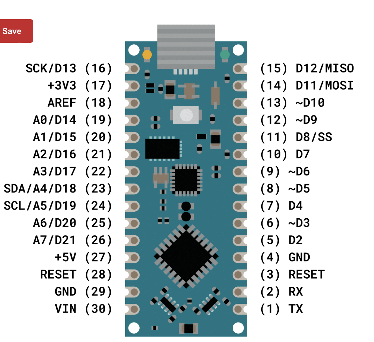
AcronymWire Color Use GND GND Black Ground 5V 3-5V White Power D13 CLK Grey Clock D12 MISO Purple Microcontroller In/Serial Out D11 MOSI Blue Microcontroller Out/Serial In D8 CS Green Chip Select D9 D/C Yellow Data/Command Select RST RST Orange Reset Lite Red Backlight on/off (on by default) ![]()
![]()
Here is an example of keyboard logic: https://www.gammon.com.au/forum/?id=14175. The DSKY has a 7x3 keyboard thus requiring 10 digital input pins. I could have connected each key to its own pin but found this solution more interesting if I ever find myself needing to implement a larger keyboard. I used the 1N4148 fast switching diodes. Each column needs a pull-up resister. Note that the Arduino has an internal pull-up resistor that can be utilized. Here is a schematic of what I wired up.
![]()
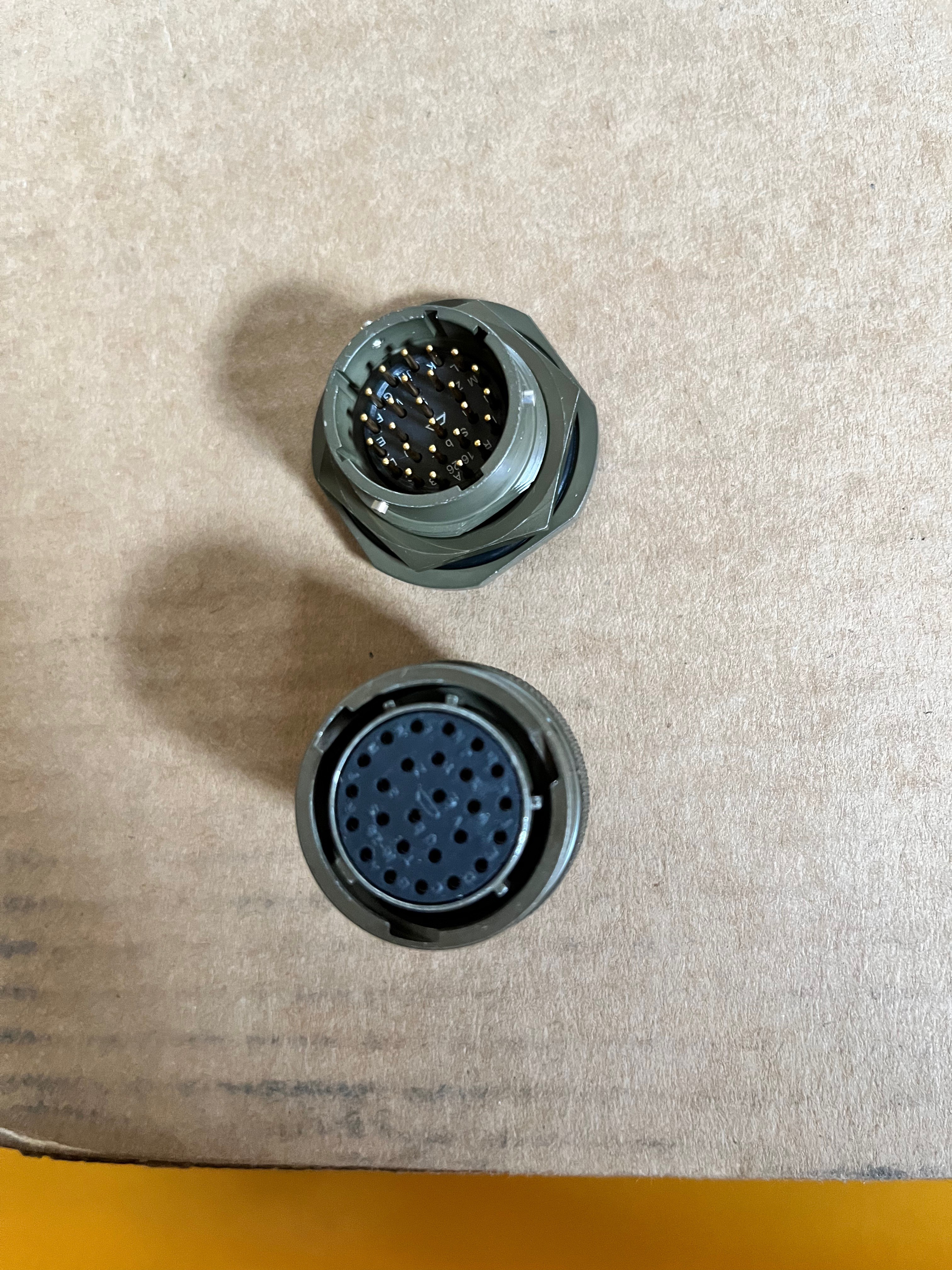
Part of making the model realistic is to use a military style jam nut connector on the back. I need 24 pins to connect the DSKY with the AGC. There are 26 pin connectors available and they look exactly like the original. The pin-outs I will use are:
Pins A-R: 15 bit Channel Bus
Pin S: CLK1: Clock 1 pulse
Pin T: RST: Reset the DSKY
Pin U: STBY: Put DSKY in Standby mode
Pin V: KBD1: Get Keyboard data
Pin W: DISP: Display data on the channel bus
Pin X: INDC: Indicator data on the channel bus
Pin Y: RPRO: Read PRO key
Pin Z: KB_STR: Keyboard data is available
Pin a: PARALM: Parity alarm
Pin b: H/W Present
Here is the jam nut and its connector, very cool.
![]()
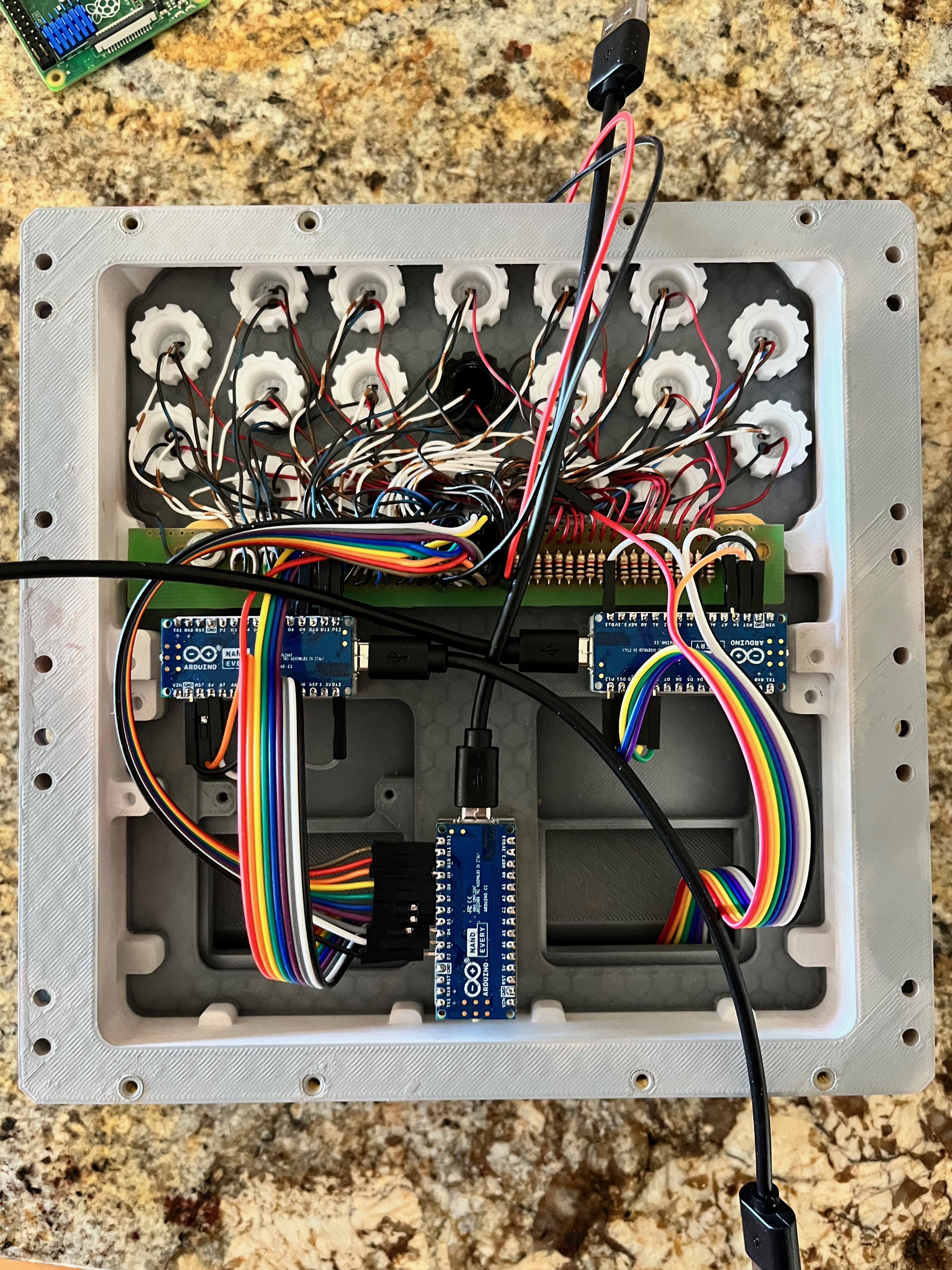
I have installed and tested the Arduinos. Here is the backside of the Front Housing showing everything assembled.
![]()
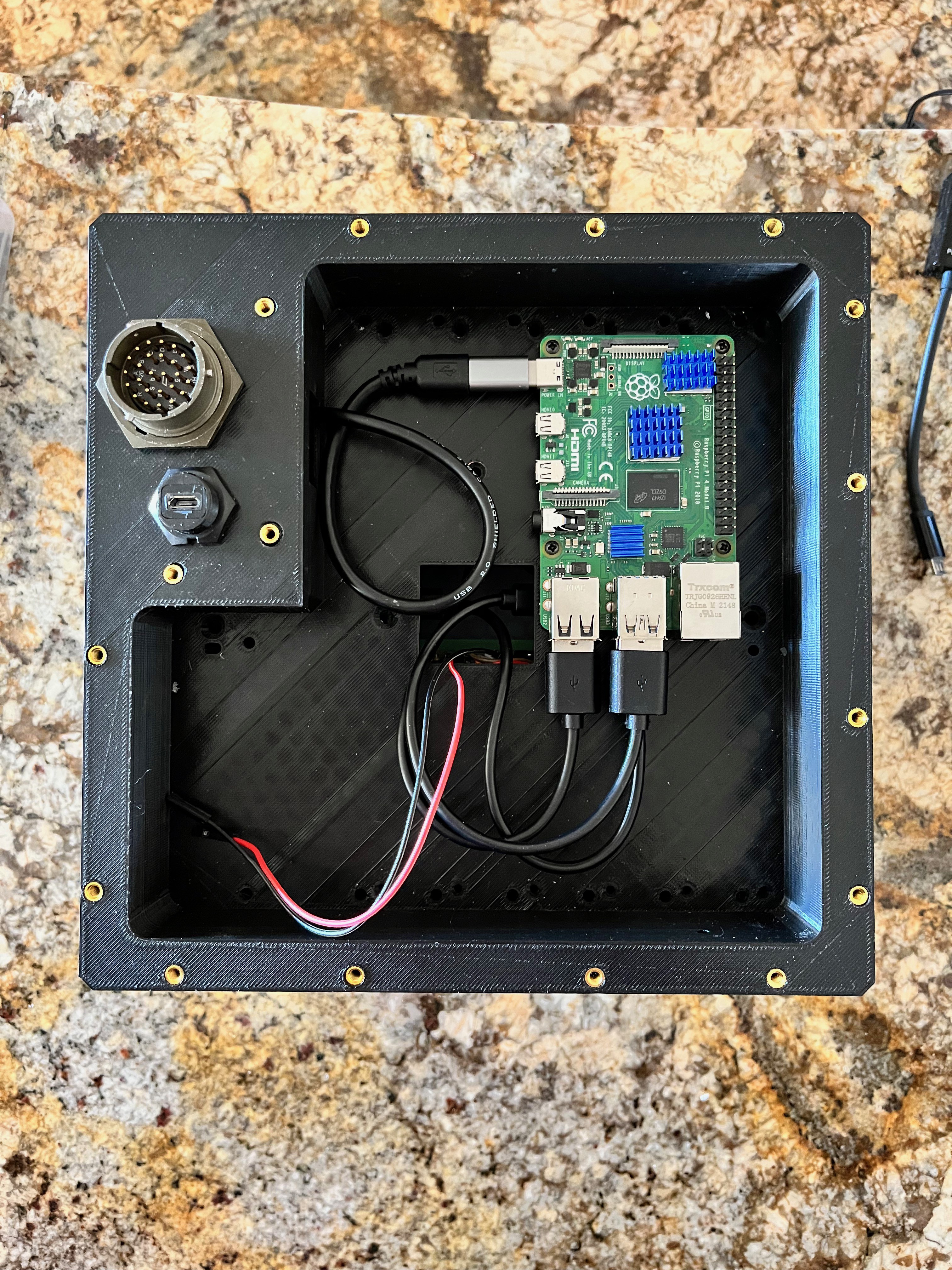
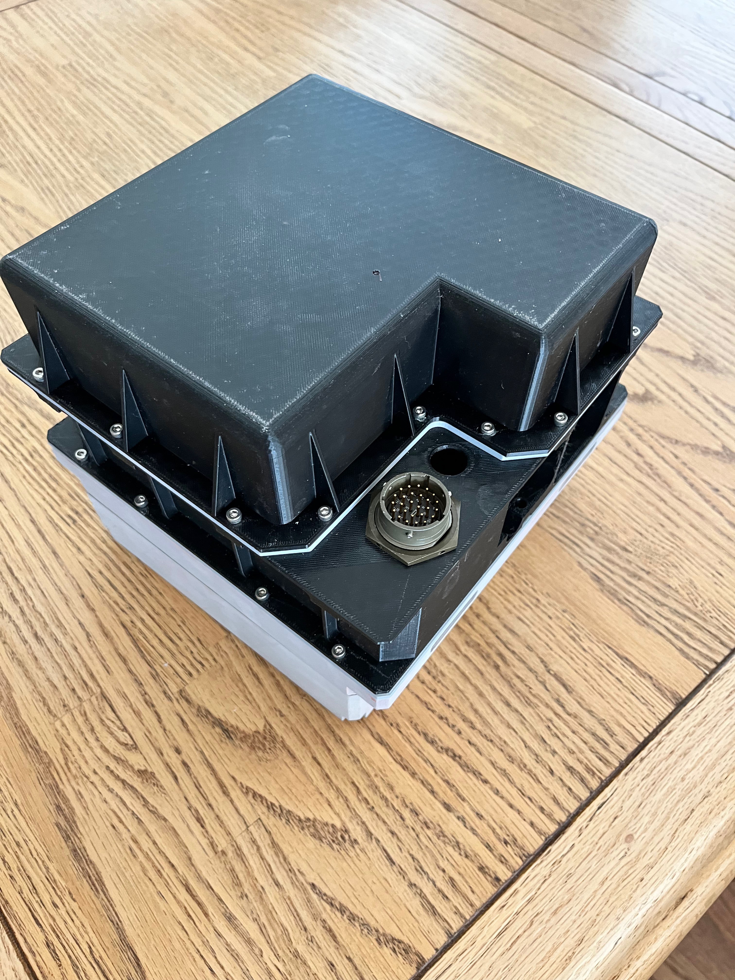
And here is the Main Housing bolted onto the front with the Raspberry Pi installed. So far I have a test program and have put the Arduino interface protocol and the Arduinos through their paces. Everything is good to go. Notice that next to the main connector I installed a micro USB port. On the original DSKY there was a bicycle tube air valve so they could fill the interior with pure nitrogen so a spark would not cause a fire.
![]()
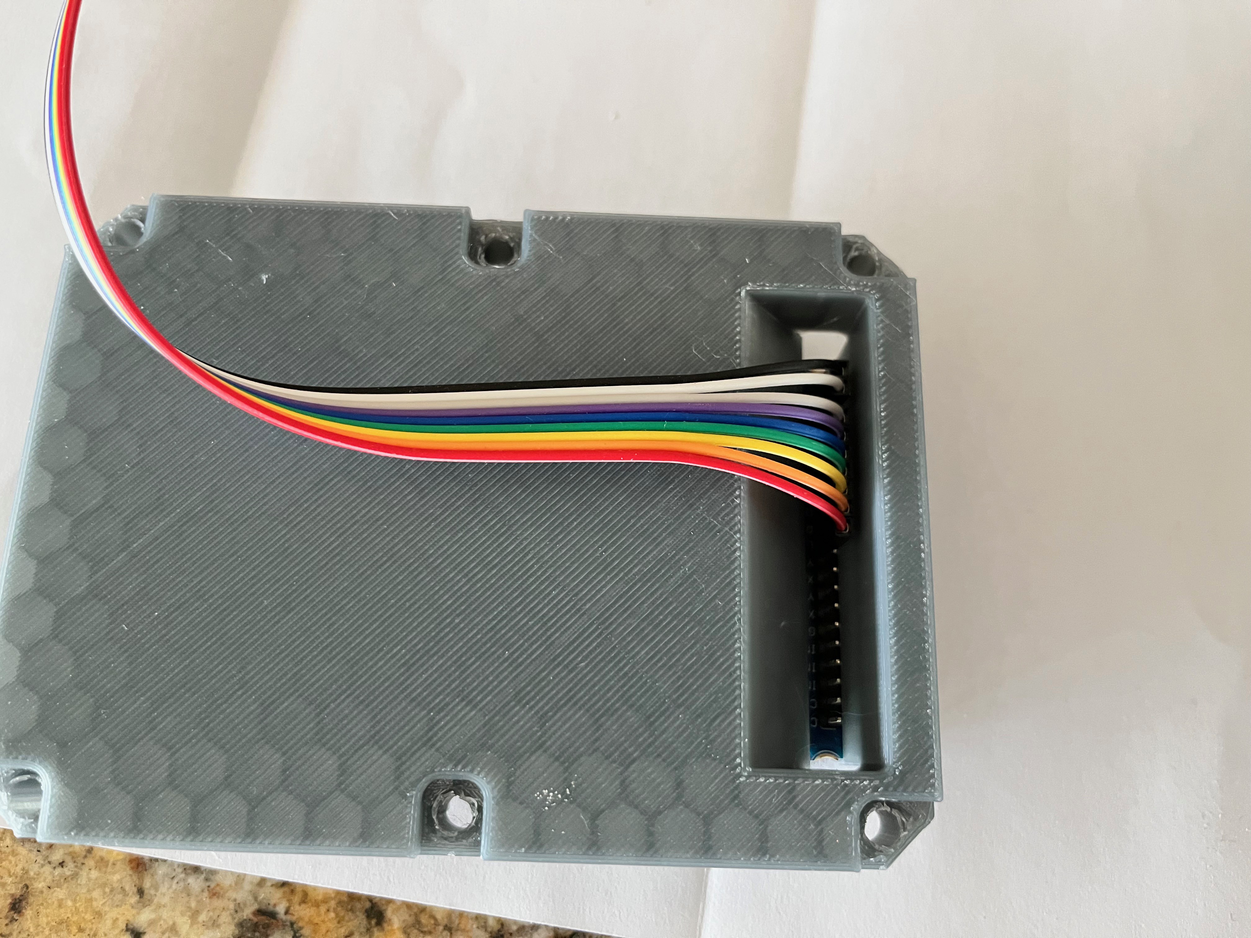
The only thing left to do hardware wise is to solder a 40-pin ribbon cable to the main connector and the 5V/GND connectors that back light the keys.
-
3D Printing
06/26/2022 at 16:57 • 0 comments3D Printing:
Having never owned a 3D printer, I purchased a printer and started taking my modeling abilities to the next level. After learning a few important lessons in 3D printing (mistakes), I was up and running. It takes a day or more to print the larger pieces so I worked on the switches and their many parts while periodically printing the larger parts.
Thanks to M. daSilva and others I have put together what I believe is the best collection of solutions for this model. What you will notice is that the parts have cryptic ID numbers. These numbers came from the original drawings. Looking at the collections of various parts out there, there seems to be some parts with multiple ID numbers. What helped me understand this device is I purchased the paper model and assembled it. I learned two things assembling this model: 1) understanding how the parts fit together and 2) I never want to build another paper model.
The following is a list of the parts I printed. I start out with a name of the part followed by the file name. The parts are listed in order from back to front to aid in assembly. Files that say "exact" are unmodified by me. Files that say "modified" are files that I modified. There are other files that relate to the key assembly and mounting the Arduinos that are not original. I have placed the CAD files out on my GitHub site.
Rear Cover : 2004900-exact-COVER,REAR
Rear Cover Gasket : 1006349-exact-GASKET,RETAINED
Main Housing : 2004974D-modified-PLATE,IDM
Main Housing Gasket : 1006350A-exact-GASKET,RETAINED
Front Housing : 2004968E-modified
Arduino Mount : ArduinoMount (attaches to underside of front housing)
Adapter Plate : 2004919E-modified-PLATE,ADAPTER
Adapter Plate Gasket : 1006351-exact-GASKET
Display/Indicator Block : 1006315G-modified
DIsplay/Indicator Cover : 2004699A-modified
Front Cover : 2004929-exact-COVER,FRONT
Key Body : 2004949D-exact-HOUSING
Key Housing : 2003926-reconstructed-HOUSING
Key Shaft : 2004948B-modified-SHAFT
Key Nut : Nut
Key Caps : (19 files located in the Keys sub-directory)
Here is the first significant part I printed, the front cover.
![]()
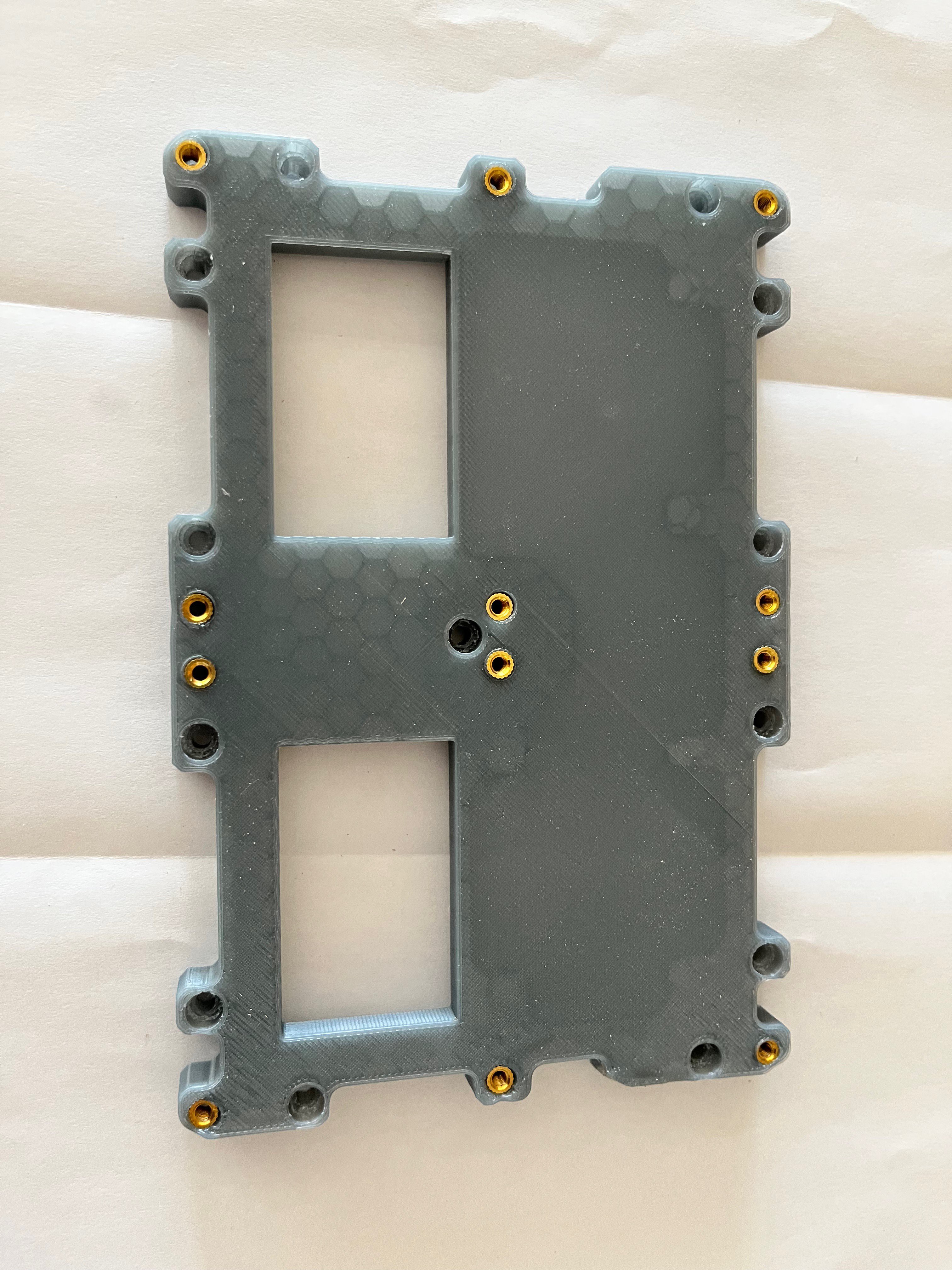
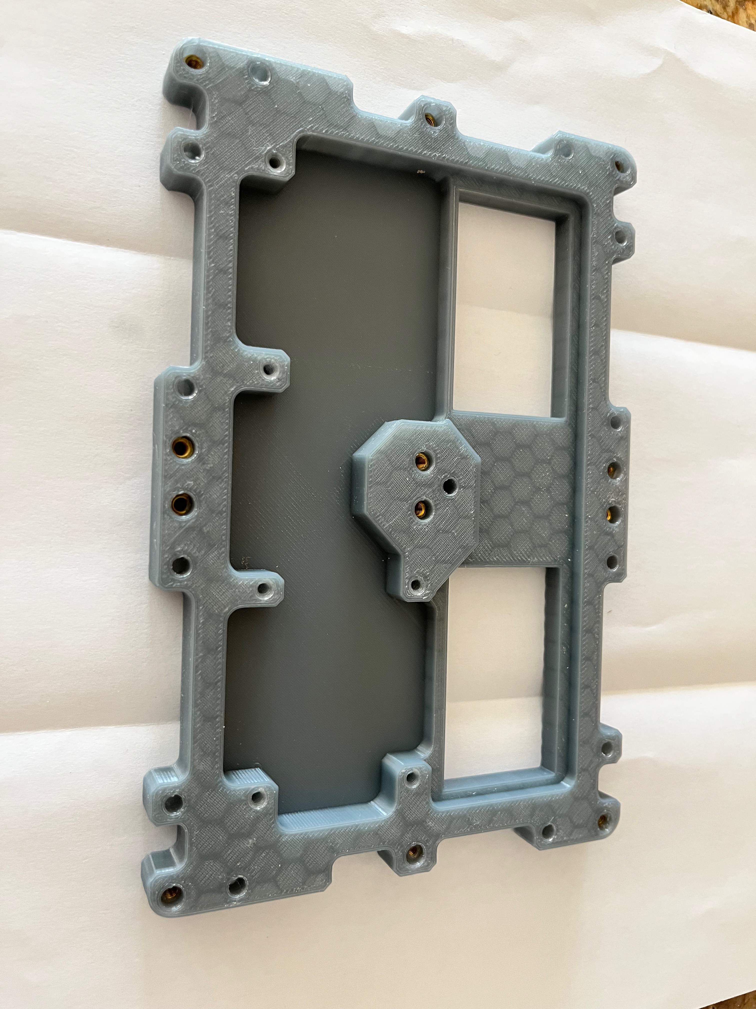
And here is the front and back of the adapter plate. Notice the inserts used to screw the pieces together. I use a hand held torch to warm the inserts and then carefully push them into the plastic using a long screw, taking care to keep the insert perpendicular while the plastic hardens. You can also see that I created two holes to route wires from the LCD panels to the Arduino Nanos.
![]()
![]()
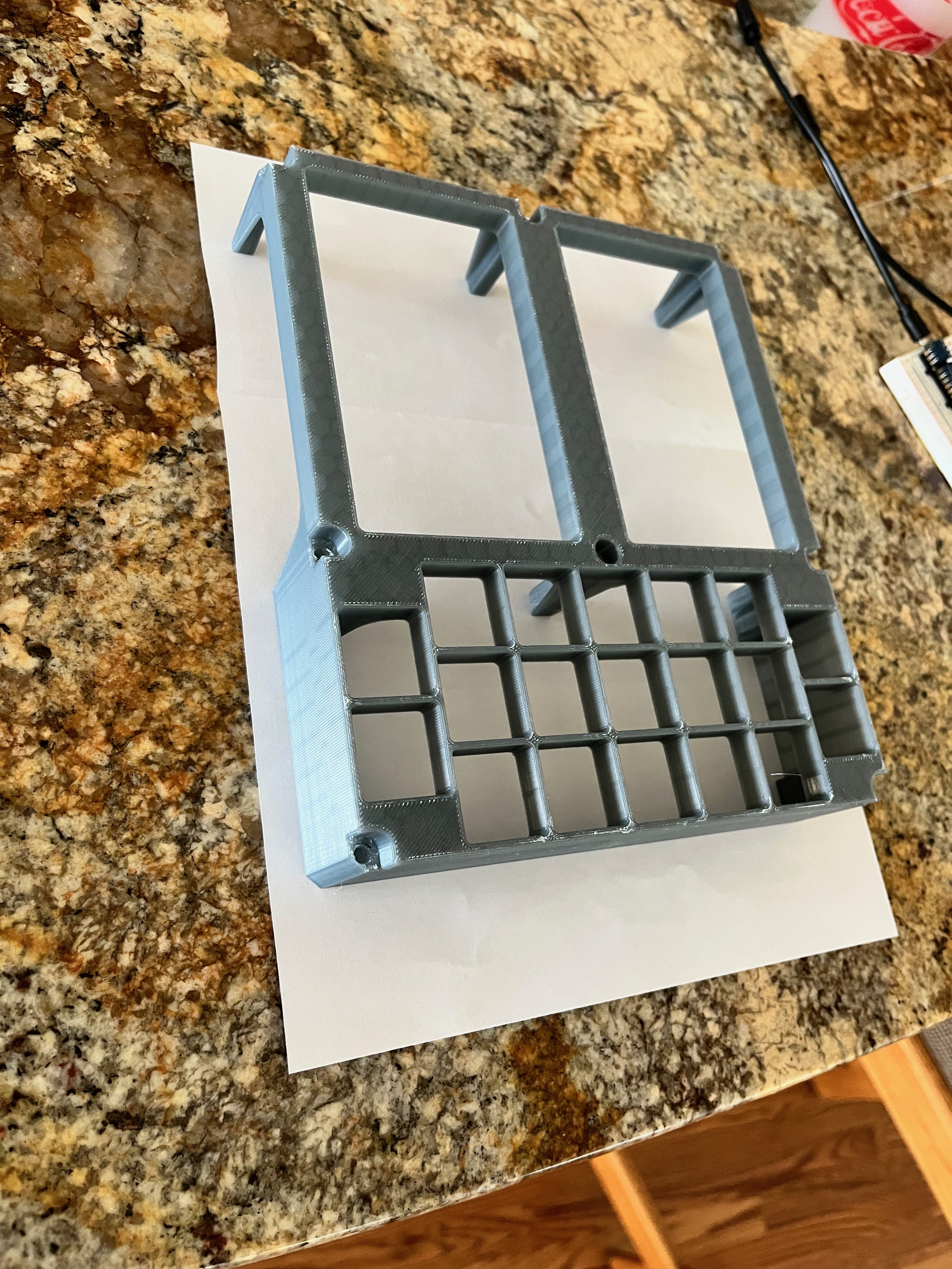
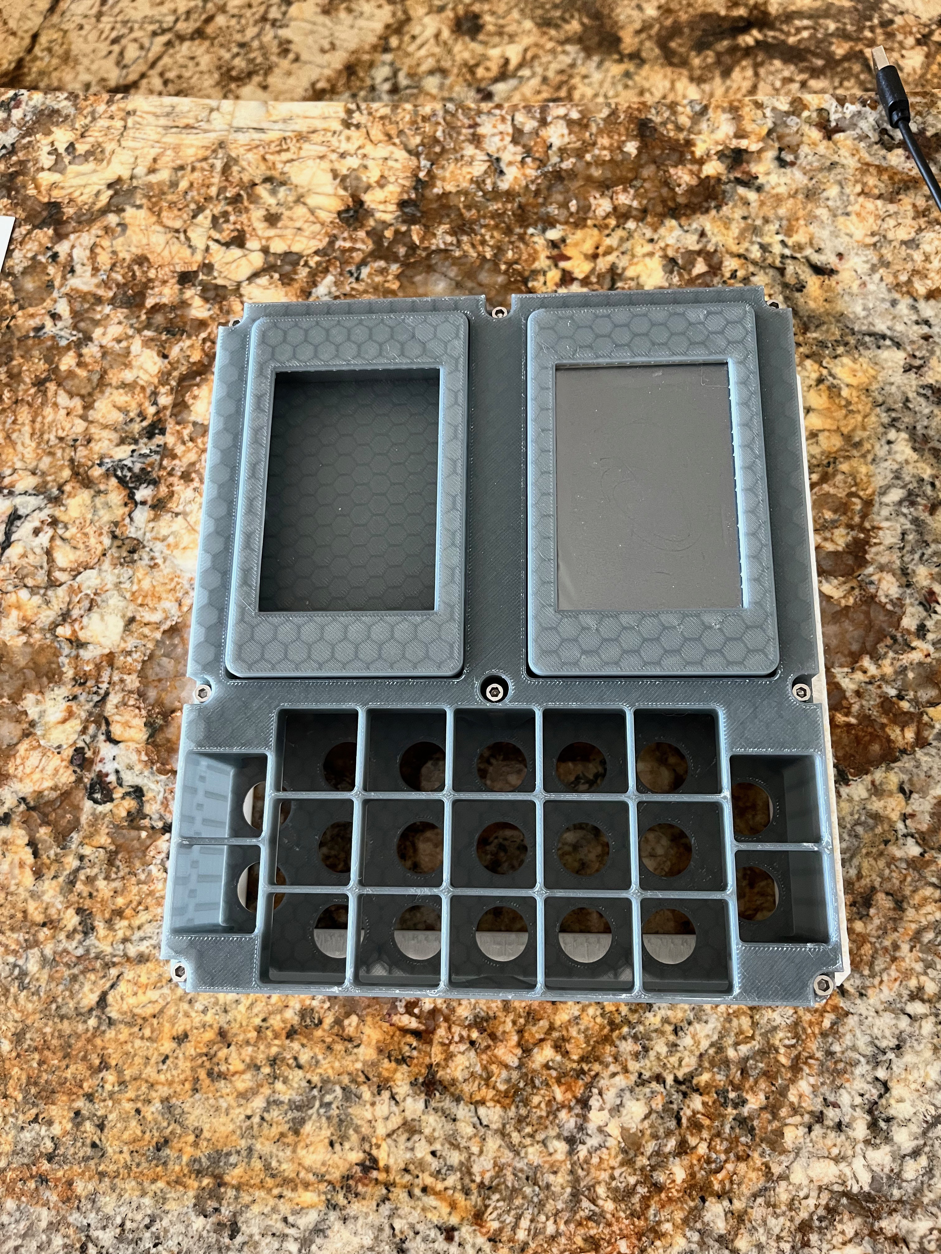
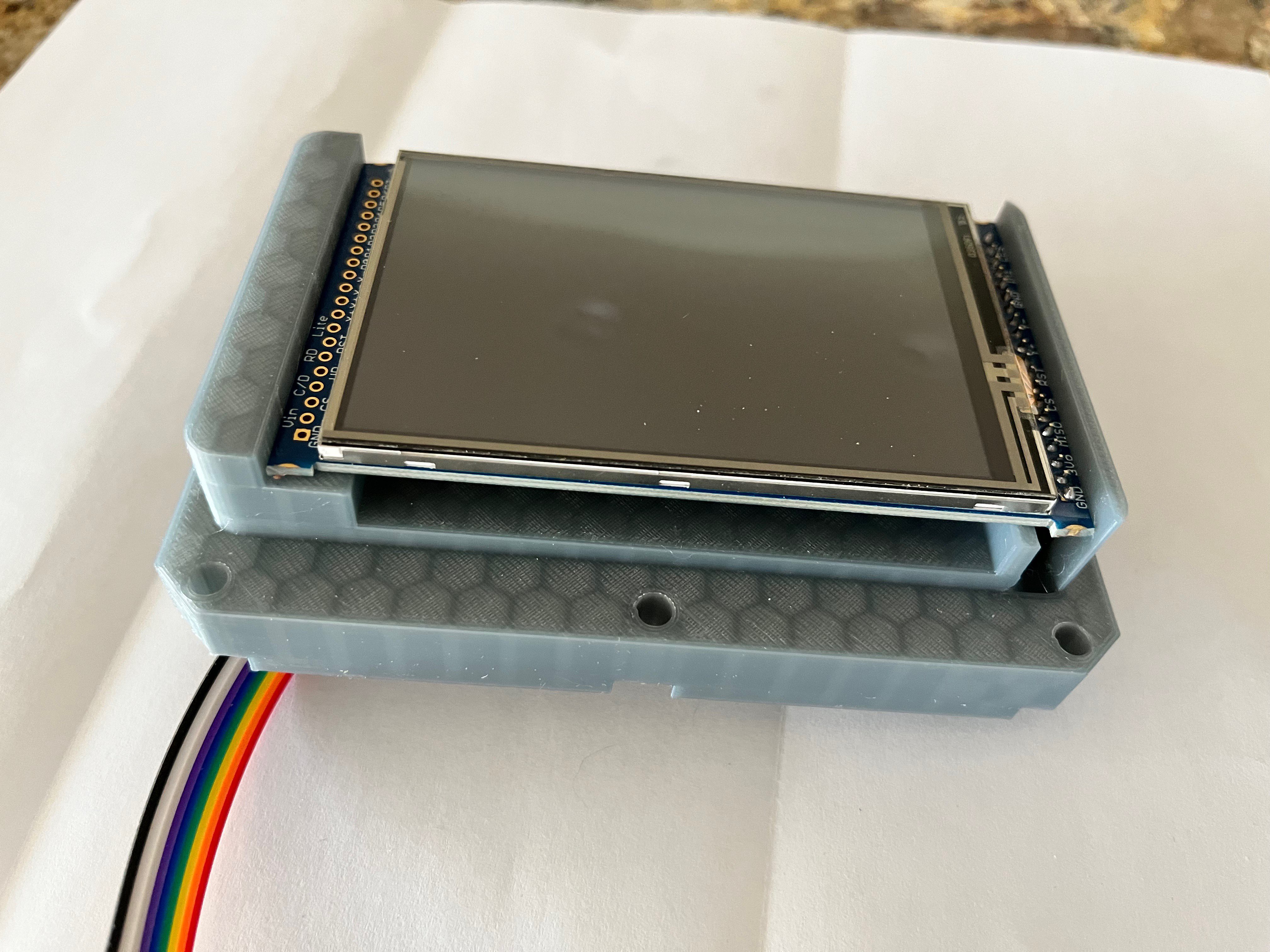
I won't show every part but here is the front 1/3 of the DSKY which consists of 11 printed parts. I have installed one of the LCD panels. The other one is being used to develop code.
![]()
To mount the LCDs I needed to make the opening in display covers a bit smaller and I modified the underlying block to press fit the LCD board and create a hole for the wires to pass. Notice that I cut off the mounting tabs of the display to get the display to fit under the cover.
![]()
![]()
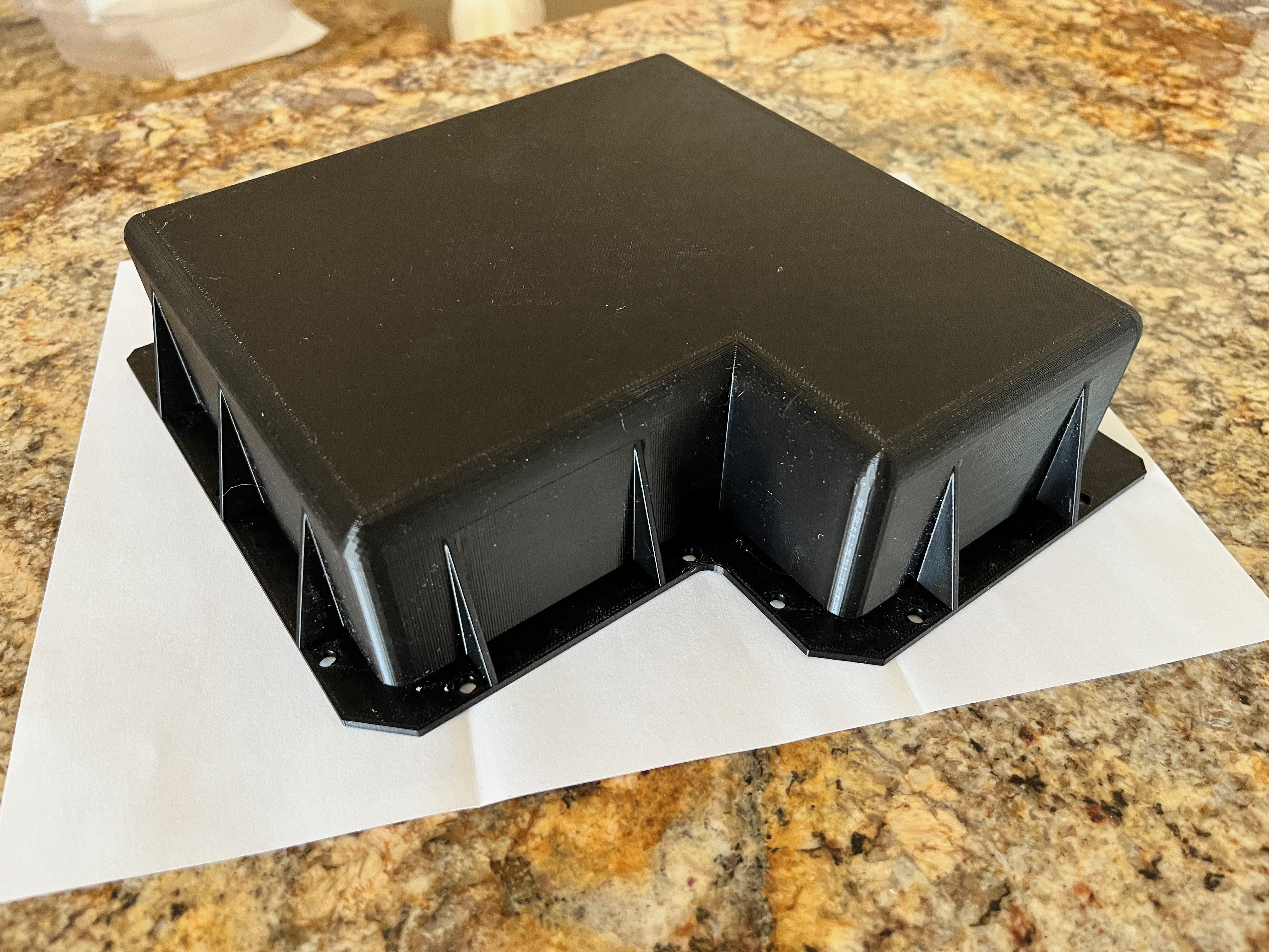
Here is the back cover finally complete. It took 36 hours to print. Since this part is supposed to be black and it came out so well, I probably will leave this part as is.
![]()
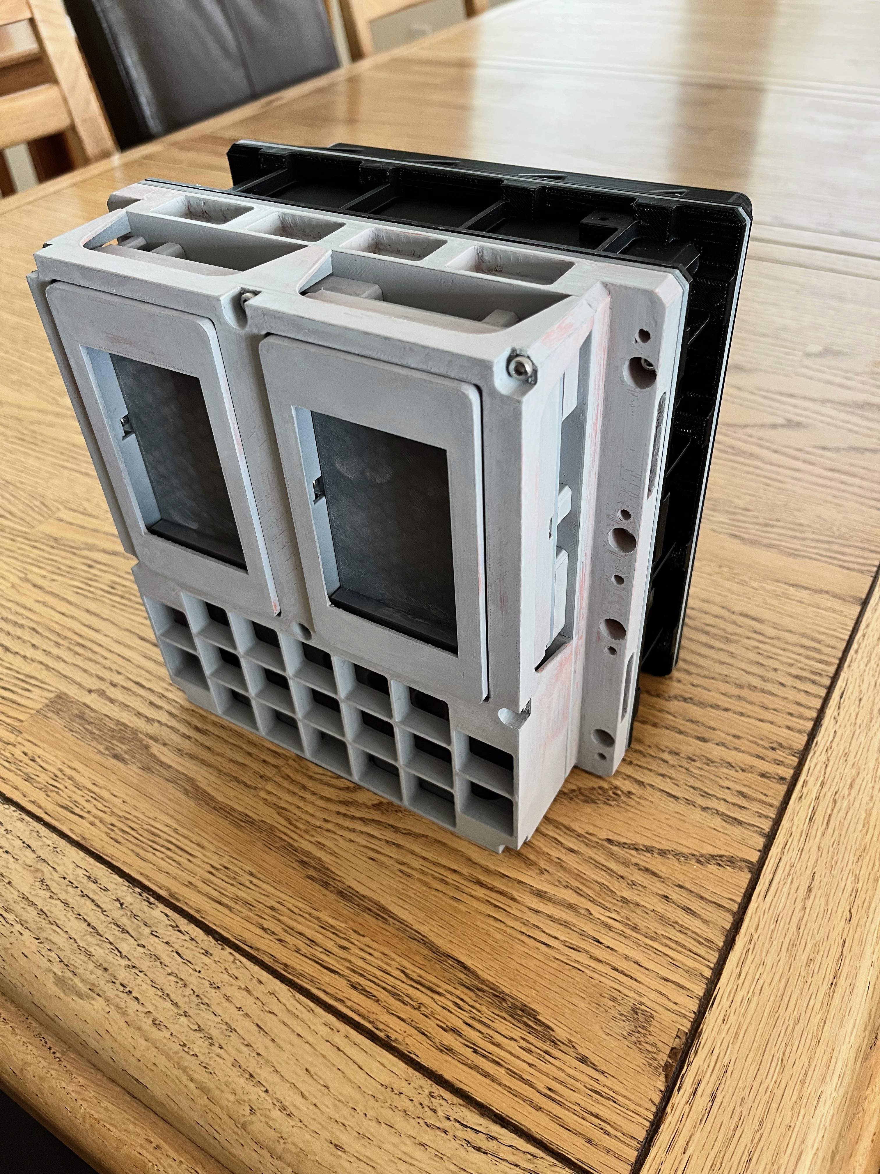
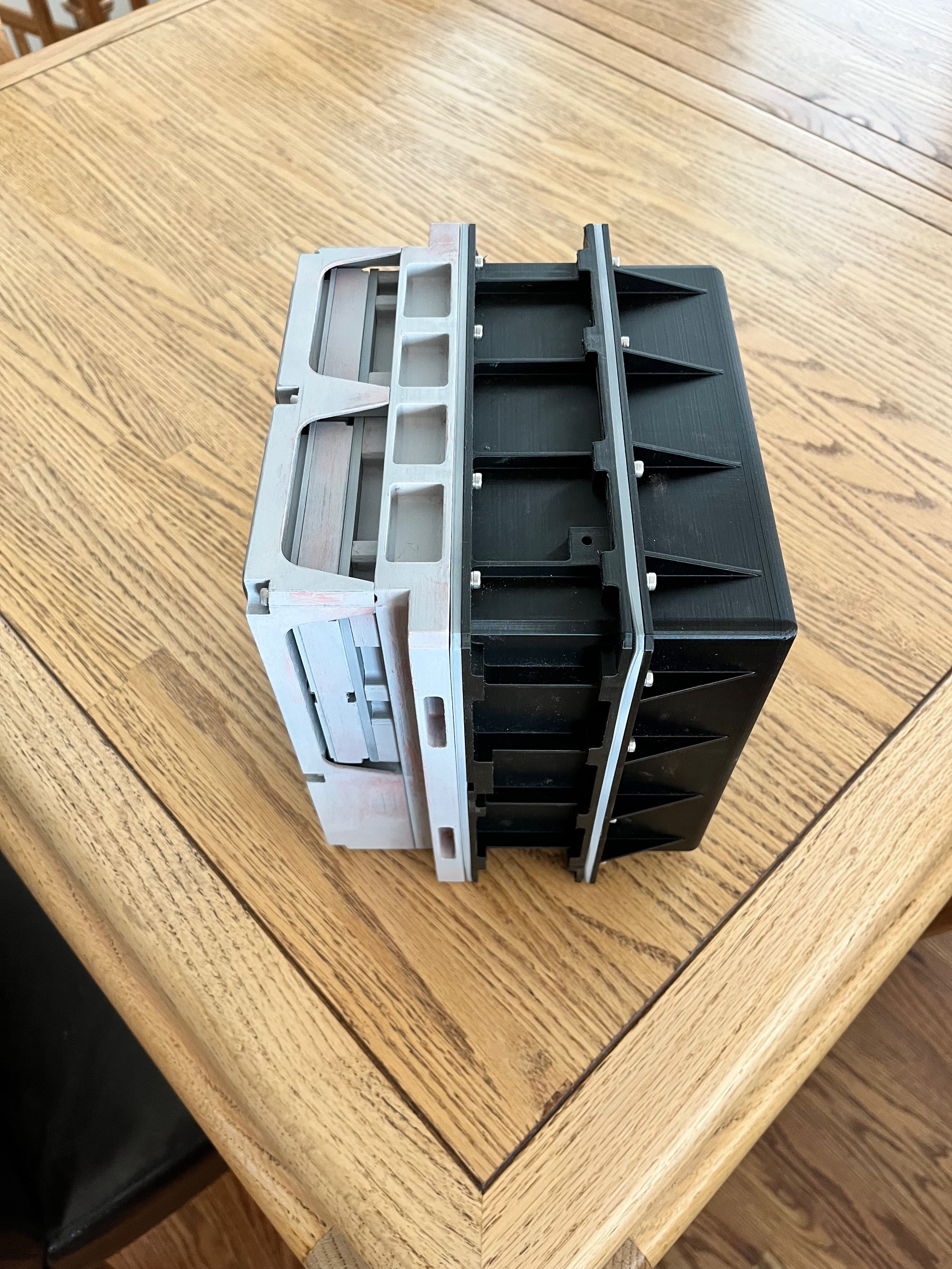
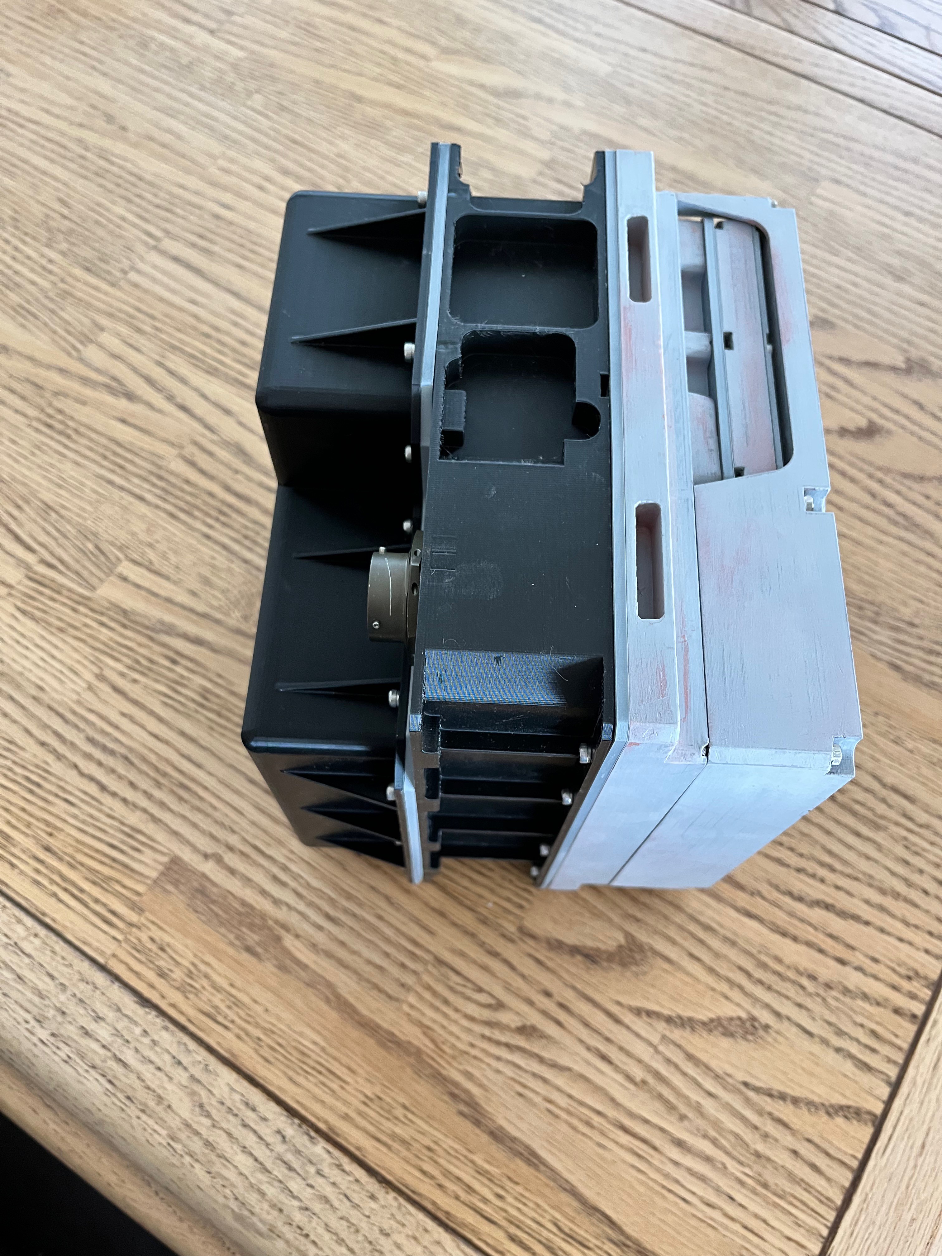
I have now completed the 3D printing of the parts and have assembled them to test the fit. Everything came together perfectly. Here are some pictures of the plastic. I did not install the keys yet because I am still waiting for paint to be delivered.
![]()
![]()
![]()
![]()
DSKY
Create a working DSKY using a 3D printer and my AGC simulator running on a Raspberry Pi and slave Arduino Nanos.
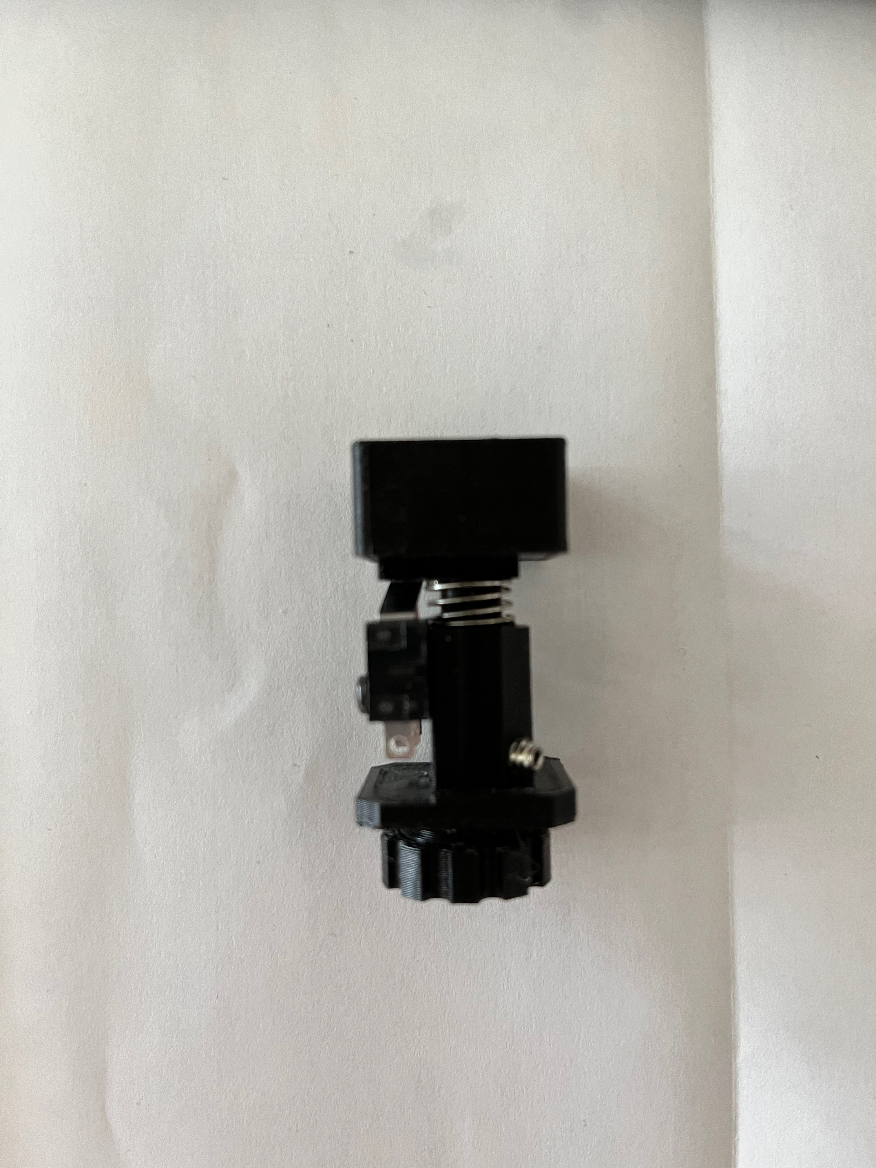
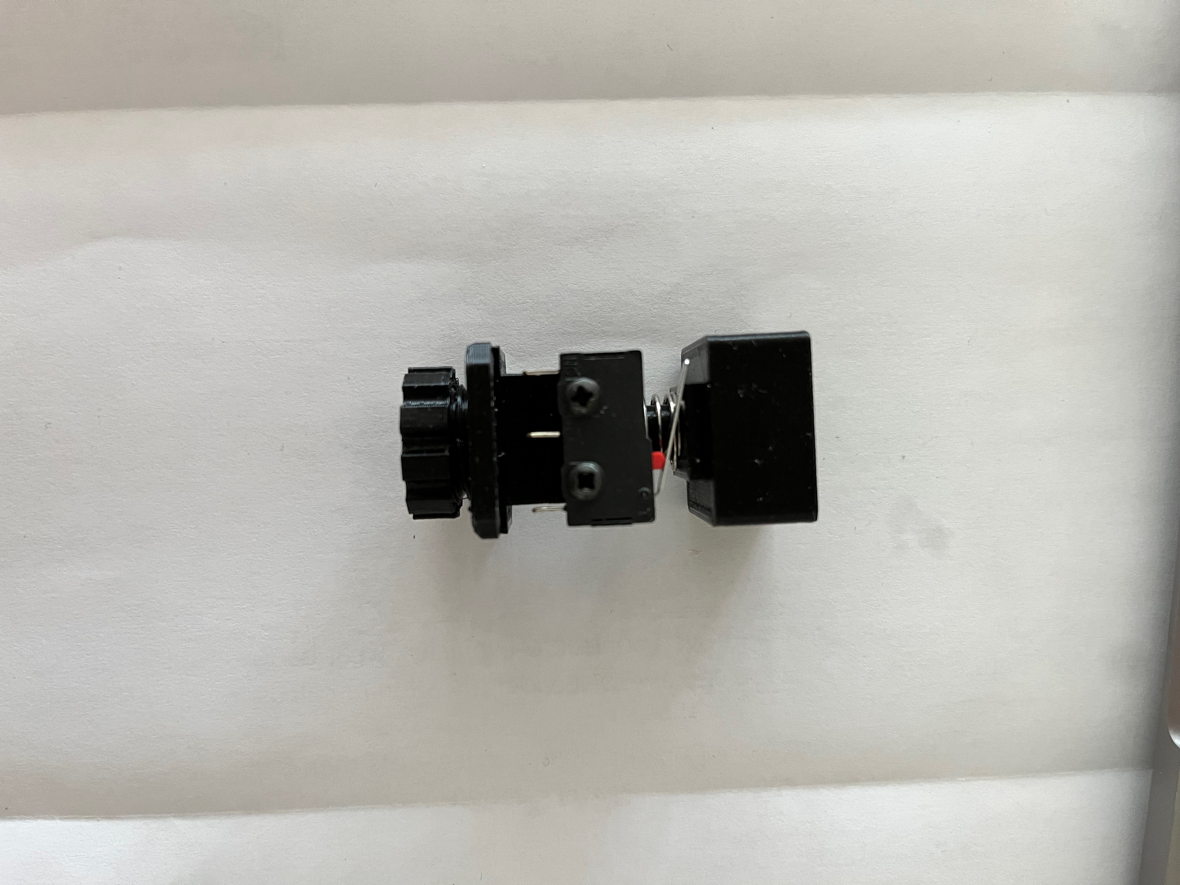
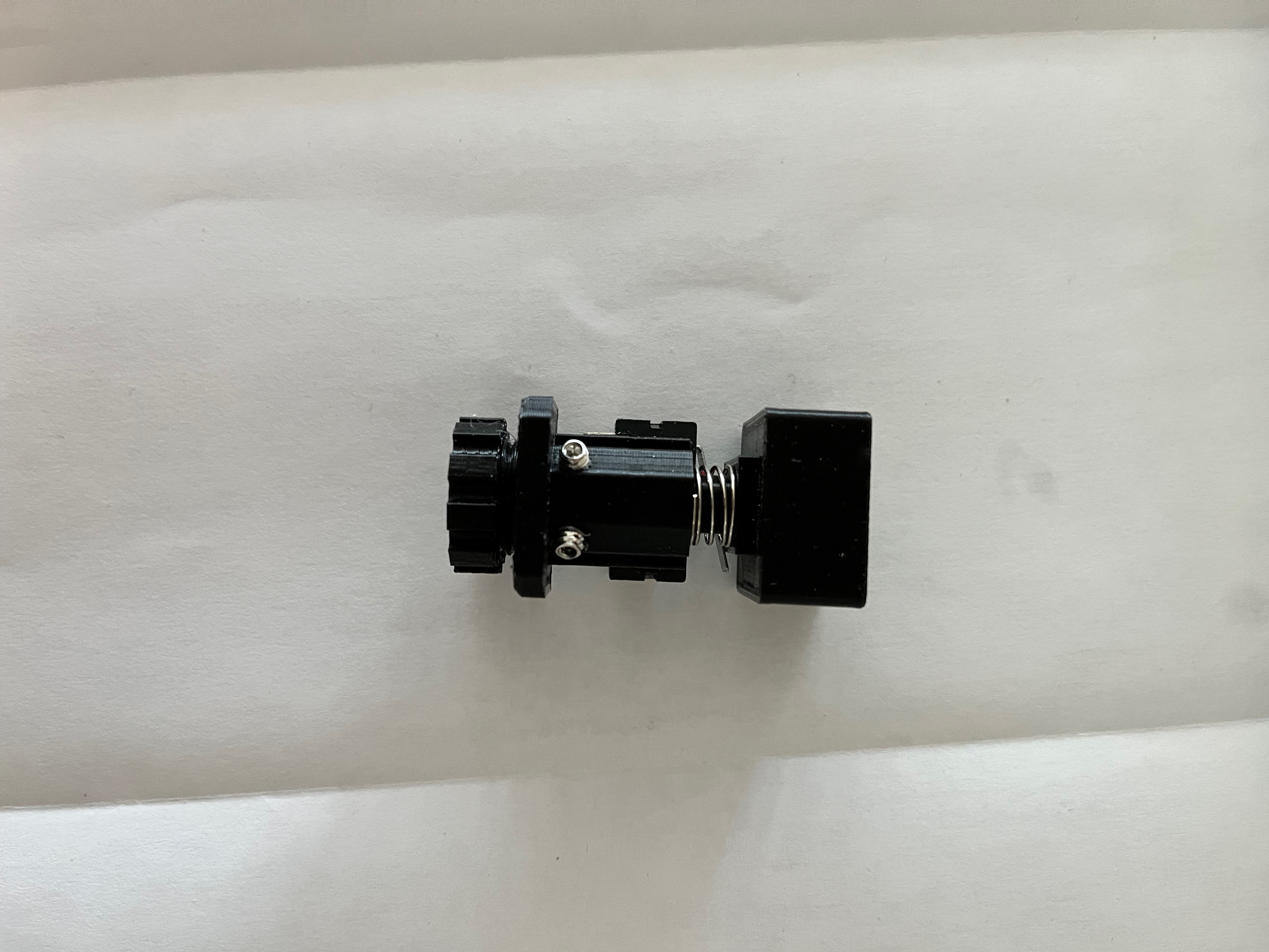 For the large nut that holds the switch assembly down I created the nut in the CAD system and then scaled it up, something like 10%, I don't remember the exact value. Without the scale up the nut was too tight a fit. To install the set screws, instead of scaling up the threads I chose to simply tap the hole for a perfect fit. I first drilled each hole to 3/32" and then tapped them with a 6-32 tap. For the smaller holes that hold down the microswitch I did not have a 2-56 tap in my set so I drilled those holes with a 5/64" bit and simply installed the screws. The plastic is pliable enough that the screw made its own threads.