Close
0%
0%

Battery Destroyer

Alkaline Battery recharger (upto 800% more life)

Similar projects worth following
For the 1KB challenge. This is a basic battery charger for old non-rechargeable AA/AAA batteries, made with spare bits + an ATmega.

Made from a couple of old IR remote controls, to recharge 'other' remote control batteries. I tried to aim for a novel entry, which does something slightly 'useful'. And of course it runs off USB power.

Using the standard Amtel Studio 6, the compiled code is under 900 bytes. And the attached source contains the binary I used.

.

This long video explains the setup, construction and some testing...

.

I quick call out to the best line in the code:

sleep_mode();

without "you", I would have to add more components.

Battery-Charger-Source-tweaked.zip

Atmel Studio or similar

force-download - 11.45 kB - 12/19/2016 at 18:53

Download

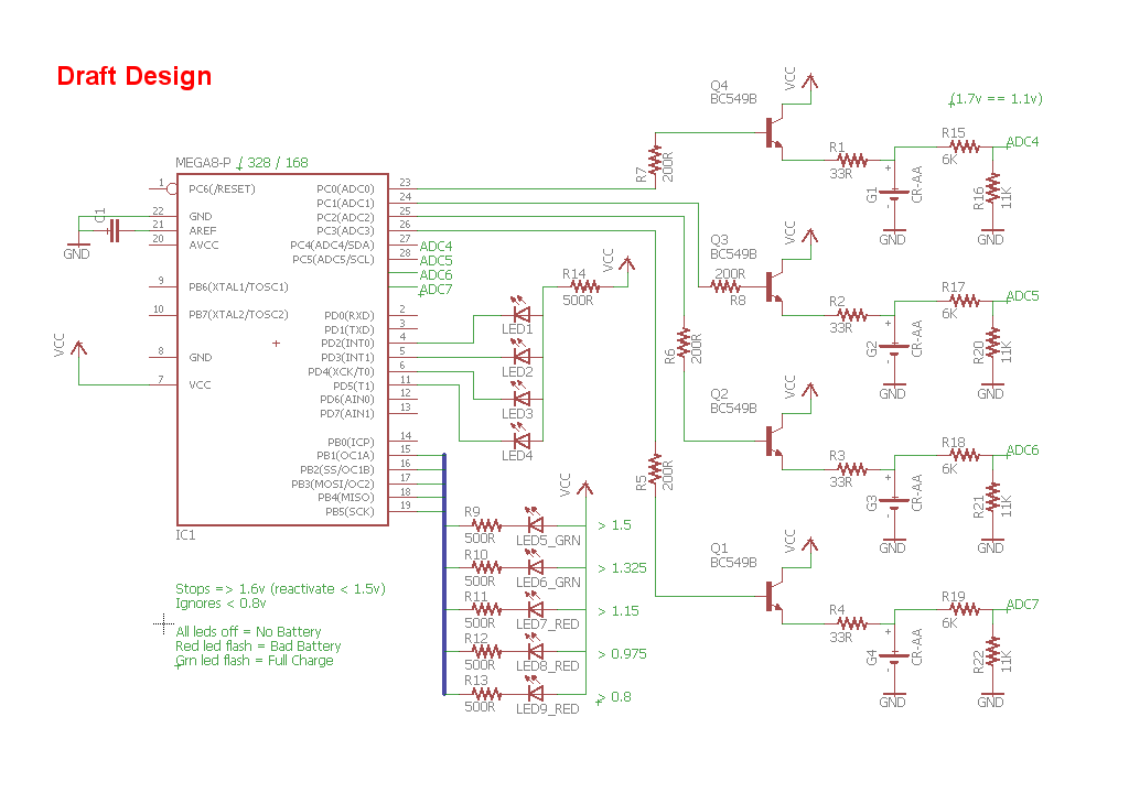
Battery-Charger-Schematic.sch

Eagle (Quick Schematic, no PCB)

sch - 339.16 kB - 12/11/2016 at 03:51

Download

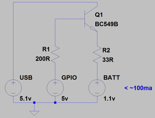
Quick-Current-Test.asc

LTspice

asc - 955.00 bytes - 12/11/2016 at 03:52

Download

  • 1 × ATmega168 (or similar) Microcontroller
  • 4 × BC549 Discrete Semiconductors / Transistors, MOSFETs, FETs, IGBTs
  • 20 × 100 Omh Resistors or 4x 200R & 4x 33R
  • 4 × 6K8 Resistors
  • 4 × 8K2 Resistors

View all 16 components

View all 4 project logs

  • 1
    Step 1

    The build instructions are laid out in the video above (13:09)

View all instructions

Enjoy this project?

Share

Discussions

ActualDragon wrote 01/04/2017 at 18:12 point

a battery destroyer that gives up to "800% more life"? wtf?

  Are you sure? yes | no

Catch a Soldering Iron wrote 12/01/2016 at 09:53 point

Hello, op-amps are not nesecary here.  The resistors 6K/11K create > 5K impendance for the ADC.  Adding a cap there should help.

The Internal reference for a 328 / 168 is 1.1V   (0.99v in my case, read after the picture)
I did not find the correct chip to use on the circuit diagram.  I've even used the wrong battery types - but you get the idea :)

  Are you sure? yes | no

K.C. Lee wrote 11/30/2016 at 04:56 point

You could have avoid using a voltage divider for the ADC input.  A small value cap placed very near the ADC can compensate by the high source impedance of a series resistor (also act as low pass filter to help with noise.)  The high value series resistor can be used to protect the uC.  For charging battery, you want as high resolution from your ADC as you can and a voltage divider reduces it.

If you were to use a PNP and rearrange the circuit a bit, you could have a constant current source for charging the battery.   Instead of connecting R5 to ground, connect that side to the I/O pin.  Drive it low to enable charging.

It would look like this:  https://qph.ec.quoracdn.net/main-qimg-43fd6ff7a2d38980156db66d98aa791c?convert_to_webp=true

The LED acts as both a voltage reference for the constant current circuit and as a indicator.

  Are you sure? yes | no

Catch a Soldering Iron wrote 11/30/2016 at 10:04 point

Sounds reasonable, but I dont have 4 of the same PNP's to hand.  I'm just using the junk I have.

  Are you sure? yes | no

Dylan wrote 11/30/2016 at 03:53 point

For the wires to the ADC inputs, wouldn't you want a buffer/ op-amp as a follower to ensure you won't accidentally load the circuit when trying to read the voltages? It probably won't be an issue, but it may come in handy. Gotta have that precision for something that doesn't need much, right?

  Are you sure? yes | no

Catch a Soldering Iron wrote 11/30/2016 at 10:06 point

Regarding the overvoltage... I know what you mean, the datasheets does not say it can not go over the Vref.  Just as long as its upto Vcc.  I quick test shows no damage (luckily).

  Are you sure? yes | no

Dylan wrote 11/30/2016 at 18:04 point

The buffer/op-amp isn't really an overvoltage issue for the AVR/Arduino, it is just an accuracy for reading the voltage of the battery as you charge it. Though checking the input current limits for the micro wouldn't be a terrible idea, which would make either the resistor as K.C. Lee mentioned above, or the op-amp protect against that. Loading the circuit would just alter the voltage read by the ADC, which could give you incorrect results. Though what may be nice, is using the op-amp with some gain to scale the battery voltage over a wider range to get more accuracy might be something interesting to do. Like map the voltage of 1.1V to whatever voltage you want across the battery, to 0V to 5V. It isn't necessary, but might help

  Are you sure? yes | no

K.C. Lee wrote 11/30/2016 at 20:04 point

On the ATMega8, there is an option of using internal 2.56V reference.  So you are making use of about 60% of FS.  So essentially you are losing less than 1 bit of resolution.  You can do a bit of oversampling and decimation to recover about a bit or so in real life.  http://www.atmel.com/images/doc8003.pdf

Adding opamp to expand the scale does not improve on accuracy.  It merely improve on resolution.  The two terms are not interchangeable.

http://www.appmeas.co.uk/blog/index.php/2010/04/sensor-accuracy-and-resolution-explained/

The capacitor I suggested helps a lot on the ADC as it lowers the AC impedance and provides the charges for the switched cap ADC during sampling phase.  The placement is extremely important for good reading - needs low impedance so short and fat tracks and place the cap as close to the ADC input pins as possible - similar to decoupling.  If you don't do it properly, the reading could jump a bit.  I use that for a few of my projects.

  Are you sure? yes | no

Similar Projects

Does this project spark your interest?

Become a member to follow this project and never miss any updates