 hsgw ➿
-
1Install CircuitPython to pico
Prepare CircuitPython according to this instalation.
https://learn.adafruit.com/welcome-to-circuitpython -
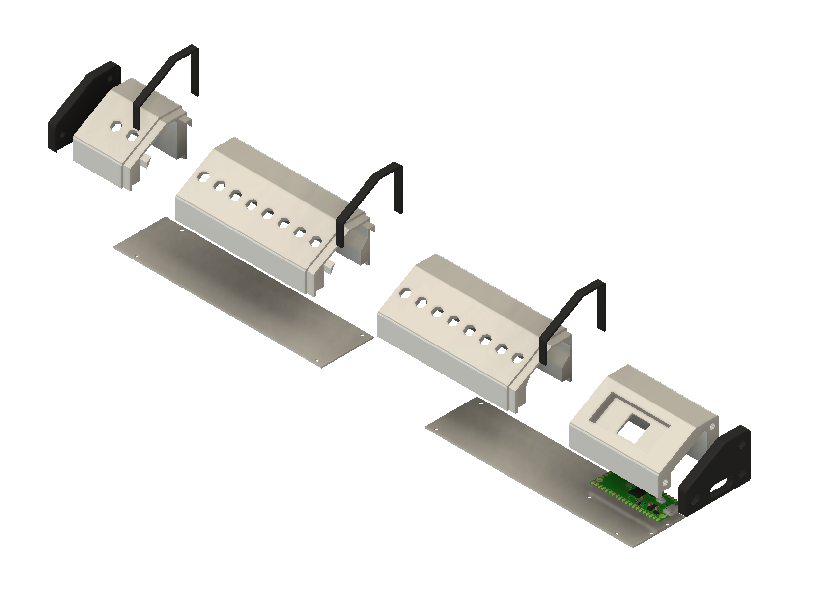
2Design and make enclosure
![]()
Design the enclosure to match toggle switches to be used.
My 3D printer doesn't have enough work area to output at once, so I designed it to be able to print out separate pieces and glue them together.
-
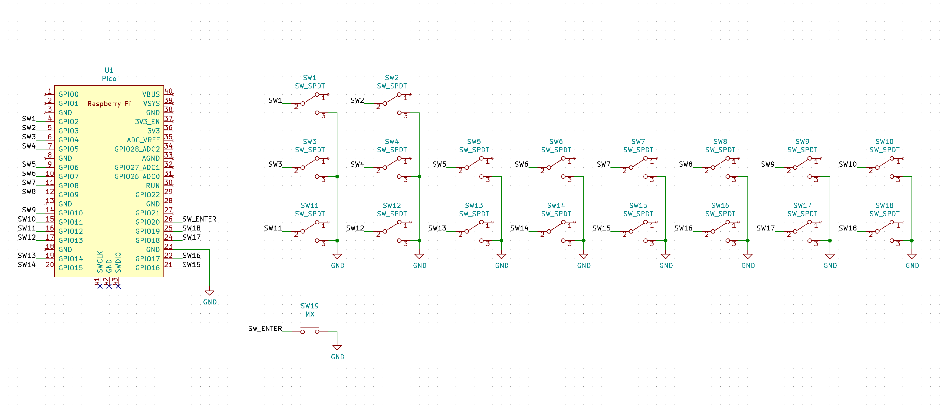
3Soldering Time!
![]()
Install toggle switches and pico, solder as shown in this schematic.
It is not important which pins are wired, as it can be easily modified in the firmware.
-
4Copy code.py to pico
code.py is here.
https://gist.github.com/hsgw/db5753c29c71fa35bb79a933cf316e77The "adafruit_deboucer", "adafruit_ticks" and "adafruit_hid" libraries are required.
Debugging code can be used to verify that all switches are working well on your serial monitor.
Discussions
Become a Hackaday.io Member
Create an account to leave a comment. Already have an account? Log In.