LEDs keep accumulating, and they are spread around in my work space. Most of them are clear, see-through LEDs. Some are dead (either by abuse, or because they are cheap Chinese diodes).
Most of them are high intensity LEDs, and they often need below 1 mA so they won't blind me.
In other words:
I need a way to test my LEDs to see if they work, which color they are, and find a suitable brightness.
After having used the LM317 in various projects, I had noticed that it could be used as a constant current source. This got me thinking about using it with LEDs.
Here's the circuit I came up with:
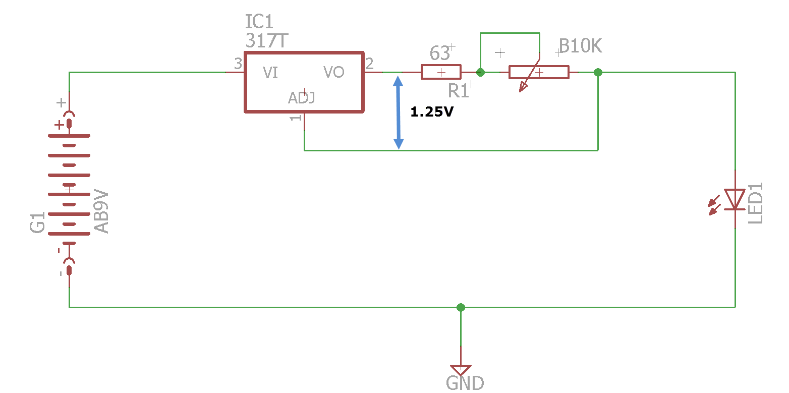
Forget for a moment that the pinout on the regulator is wrong (the attached Eagle project files are correct). Here's how it works:
- The LM317 will always keep a 1.25V reference voltage between the output and the adjust pins. Adding resistance in this loop will generate a constant current.
- I want to limit the current to a maximum of 20 mA. Knowing that, and the voltage (1.25V), using Ohm's law will give me the correct resistor: U/I = R -> 1.25/0.02 = 62.5 ohms. I settled for 63 ohms which is close enough.
- Adding 10k ohms will give a minimum current of 1.25 mA, so I put a 10k potentiometer in the loop as well. There's a linear pot in the picture above, a logarithmic one will work better.
- An amperemeter can be hooked up in series with the LED, to see what the current is.
- A voltmeter can be hooked up in parallel with the LED, to see the forward voltage drop.
- Using these two parameters, you can get the desired brightness in any circuit. Use Ohm's law or one of the many online LED calculators.
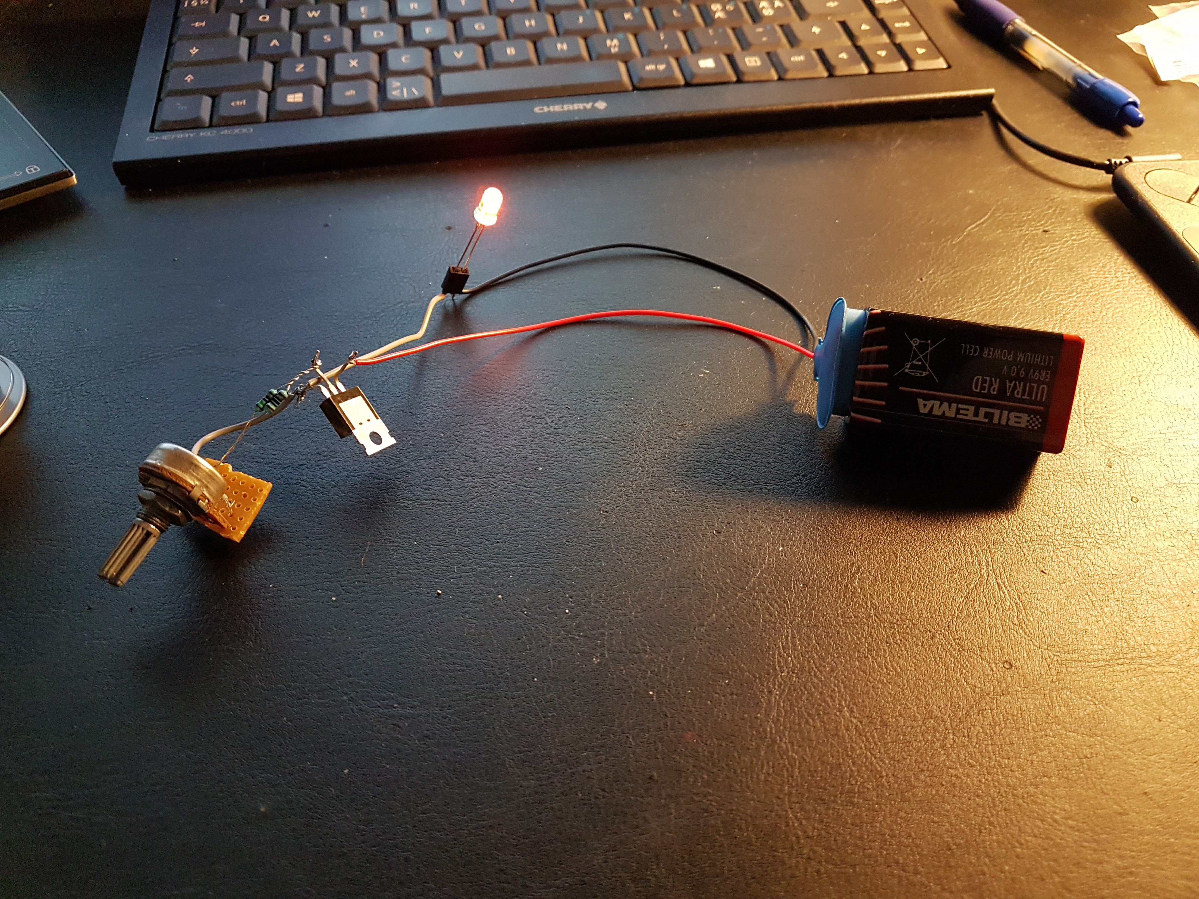
I built it, and it works.
The linear pot that I used makes the LED go darker relatively fast, a logarithmic one is better.
Discussions
Become a Hackaday.io Member
Create an account to leave a comment. Already have an account? Log In.
Here's one I like to use - Q2 regulates the drive to Q1 to keep the voltage across R1 at Q2's Vbe - so, there's always around 0.6-0.7V across R1, limiting the current. Use different R1 for more/less current. The current varies a little with temperature - as shown below, it's between 0.8 and 1.2 mA over -20 to 100C; but that's a huge range. If you're not testing your LEDs in boiling water, this might work for you :-) The exact transistors aren't critical, and you can make it with PNPs if you want the LED grounded for some reason.
Are you sure? yes | no
I looked at using transistors as well, but using the LM317 is a bit easier. I am waiting for an ammeter and a voltmeter (on a slow boat from China), and will put it all together in one enclosure.
Then I can see if the LED works, adjust to the right brightness, and get both current (I) and forward voltage drop (Uf). As long as i know the voltage of the circuit the LED's going into (U), I can find the correct resistor value with:
* R = (U -Uf) / I
Are you sure? yes | no
BTW, I thought about getting a retro analog milliammeter. They do look very nice, but it's a bit hard to actually see the exact amperage on them. So both meters will be digital.
Are you sure? yes | no
I'm getting about 2.2 mA at the lowest, this explains why. :)
Maybe I should look into other constant current sources, like the LM234, to get lower current?
EDIT: This guy seems to have figured it out:
http://electronics.stackexchange.com/questions/211249/lm317-%C2%B5a-constant-current-source-possibility
Are you sure? yes | no
Just use the variable resistor as a series for controlling current to your LED. You can get away without a constant current source as your input voltage (9V) is high enough to minimize the different between individual LED. Might want to increase R1.
Are you sure? yes | no
exactly
Are you sure? yes | no
Adding an LED as a load did work though, and it gave me a power on light:
https://hackaday.io/project/18624-muffsy-constant-current-led-tester/log/49686-getting-low-current-from-lm317
Are you sure? yes | no
Interesting, wouldn't'a thought of the minimum load-current.
I usually just use the "diode tester" built into my multimeter... it supposedly maxes out at 2V, but I've only run into a handful of LEDs it doesn't at least *dimly* light (though the measurement doesn't show up on the screen if it's higher than 2V). And, of course, since the meter's in use doing that, it's a bit difficult to do current-measurement, etc.
Forget the boring series-resistor-thing, now that you've got this thing going, might as well perfect it.
Some things to consider: If you power this thing up, *then* plug in an LED, there will be a brief moment when it tries to drive the LED with nearly 9V. LEDs are usually OK with this, it's *very brief*, but e.g. a laser-diode would most-likely blow. (and, actually, what with "bounce" of inserting the LED, it might be pulsated with 9V repeatedly before finally settling). BUT: Adding the "dummy load" at that link should probably help that.
If you wire the LED backwards, similar... And some LEDs can't take 9V reverse-voltage. (again, the dummy-load should prevent that).
Are you sure? yes | no
Apologies, looking at your new log I see I misread the schematic at that link... the dummy-load is connected directly to the Vout pin. Makes sense, but doesn't solve the "some things to consider" I put here... if those are concerns to yah... (e.g. checking an LED's polarity)
Are you sure? yes | no
LM317 minimum load is 3.5mA (typ) and 10mA (max). So the LED current regulation would start around 3.5mA. Below that you are seeing output, but the LM317 won't be regulating current.
Are you sure? yes | no