Alex
Alex-
Finch Evolved: New Boards, New Case, and a Thumbstick!
09/06/2024 at 17:38 • 1 commentGood news, everyone! I’ve successfully completed a new design for the project. In this post, I’ll give a brief overview, with more details to follow in the next project log.
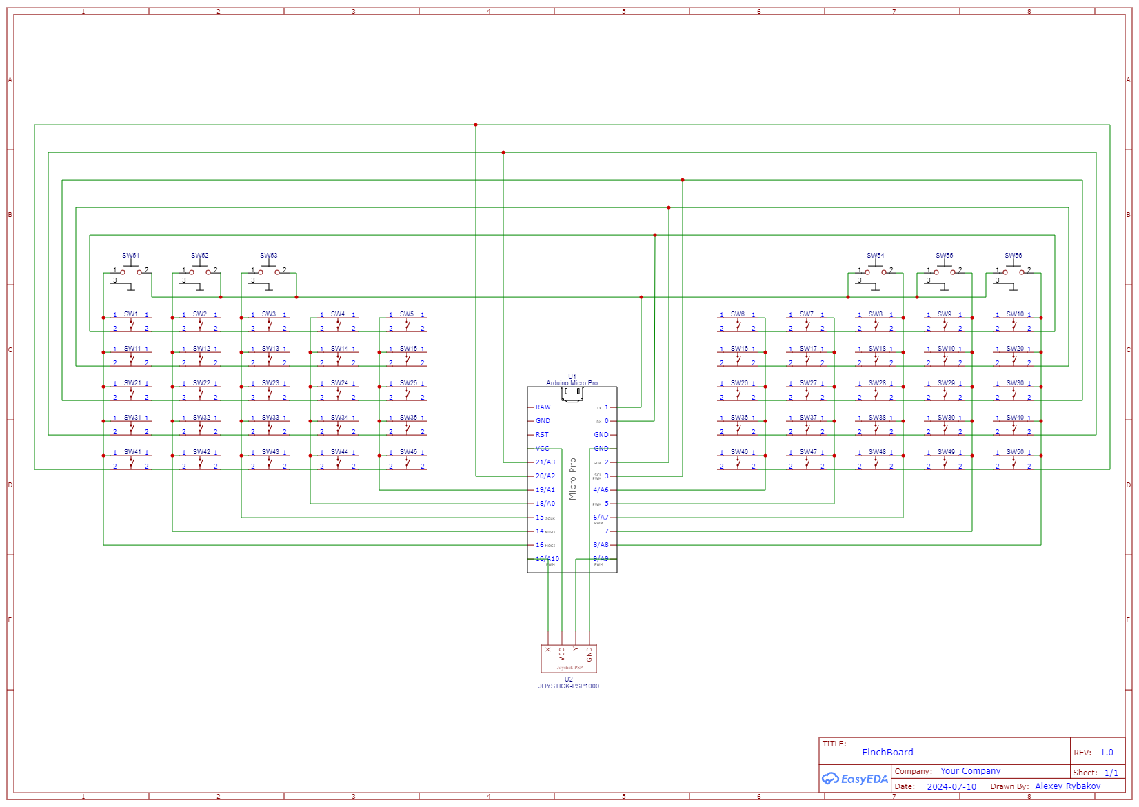
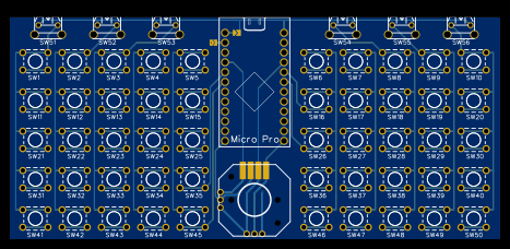
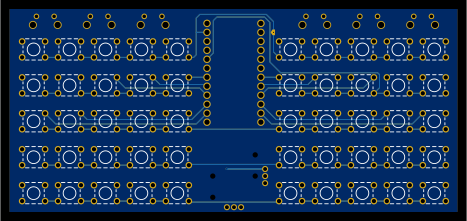
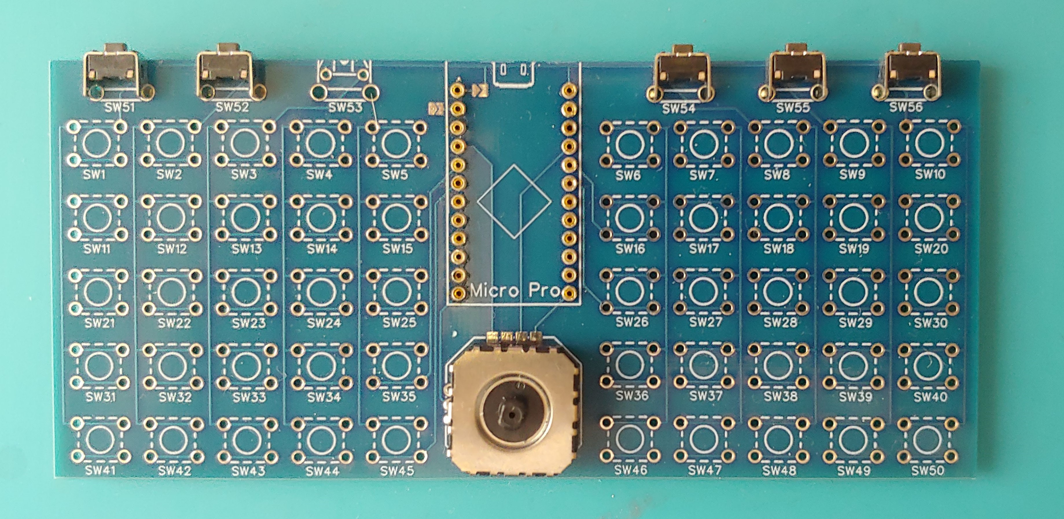
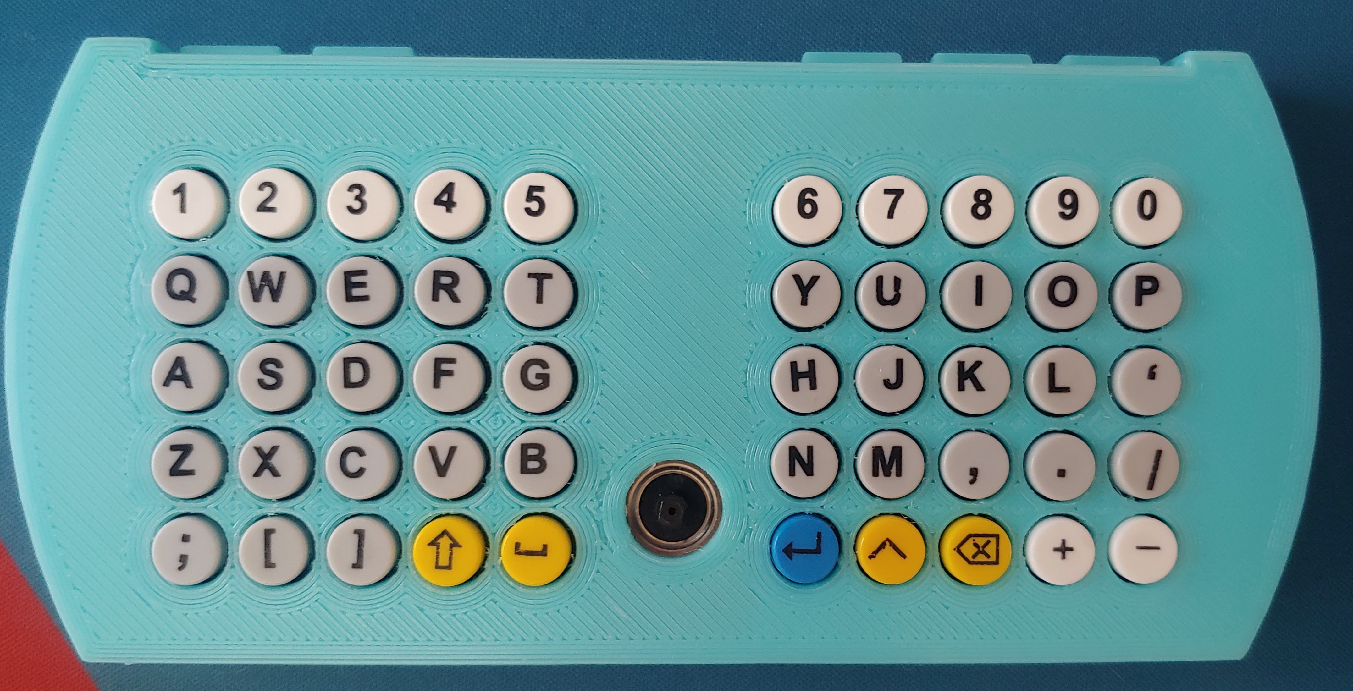
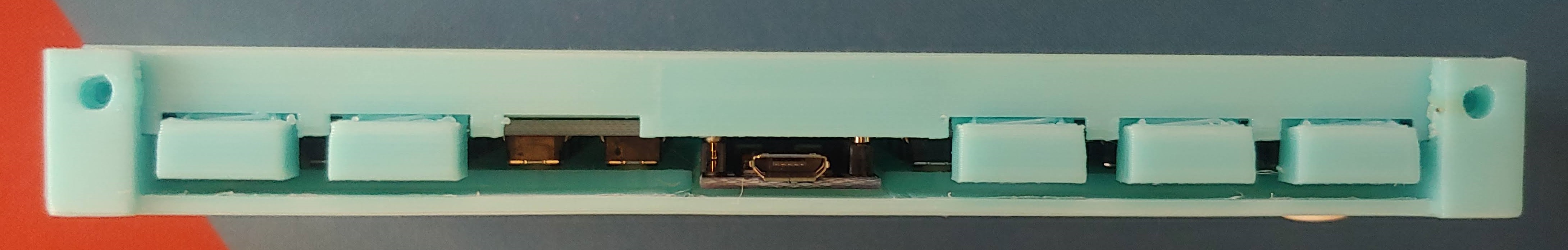
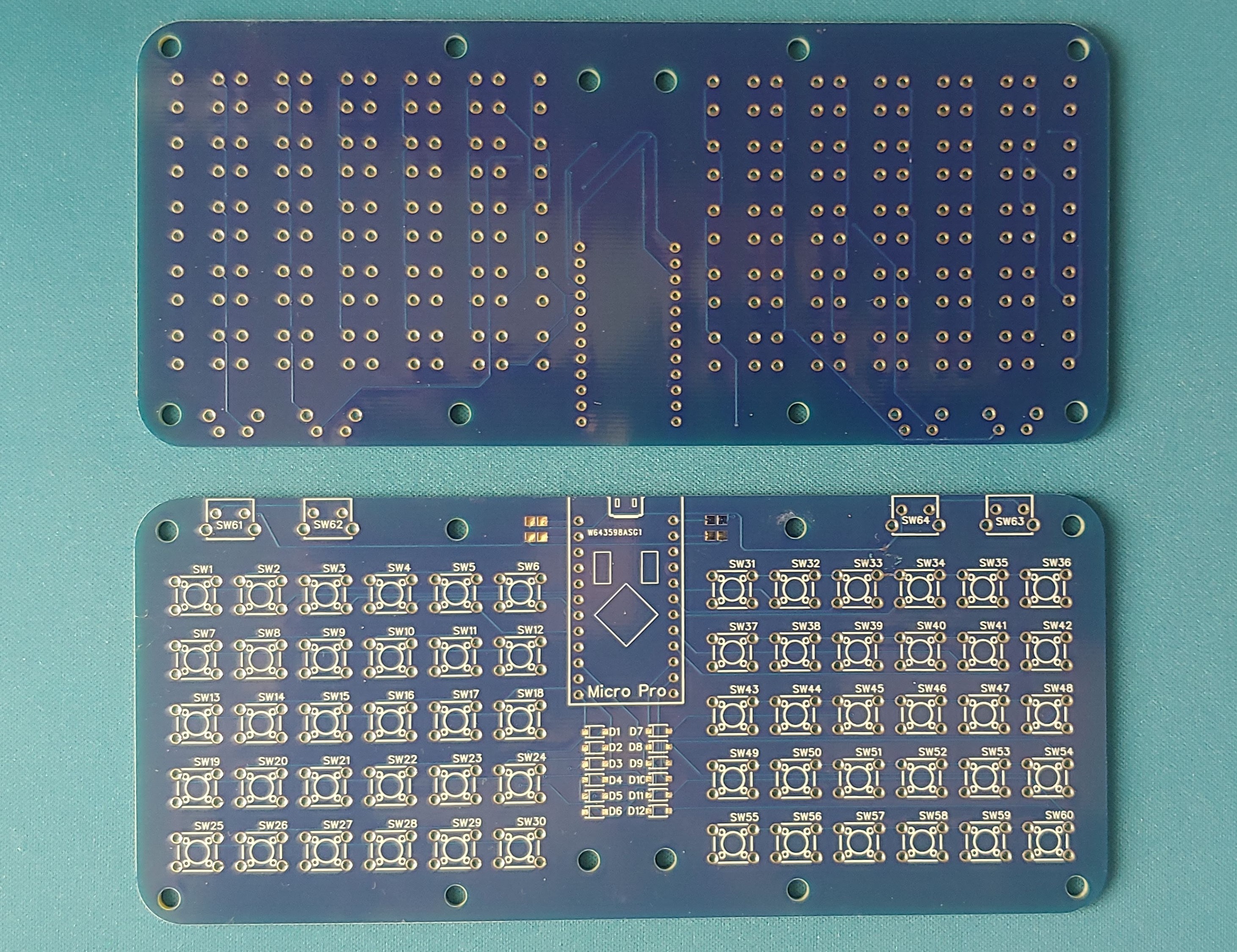
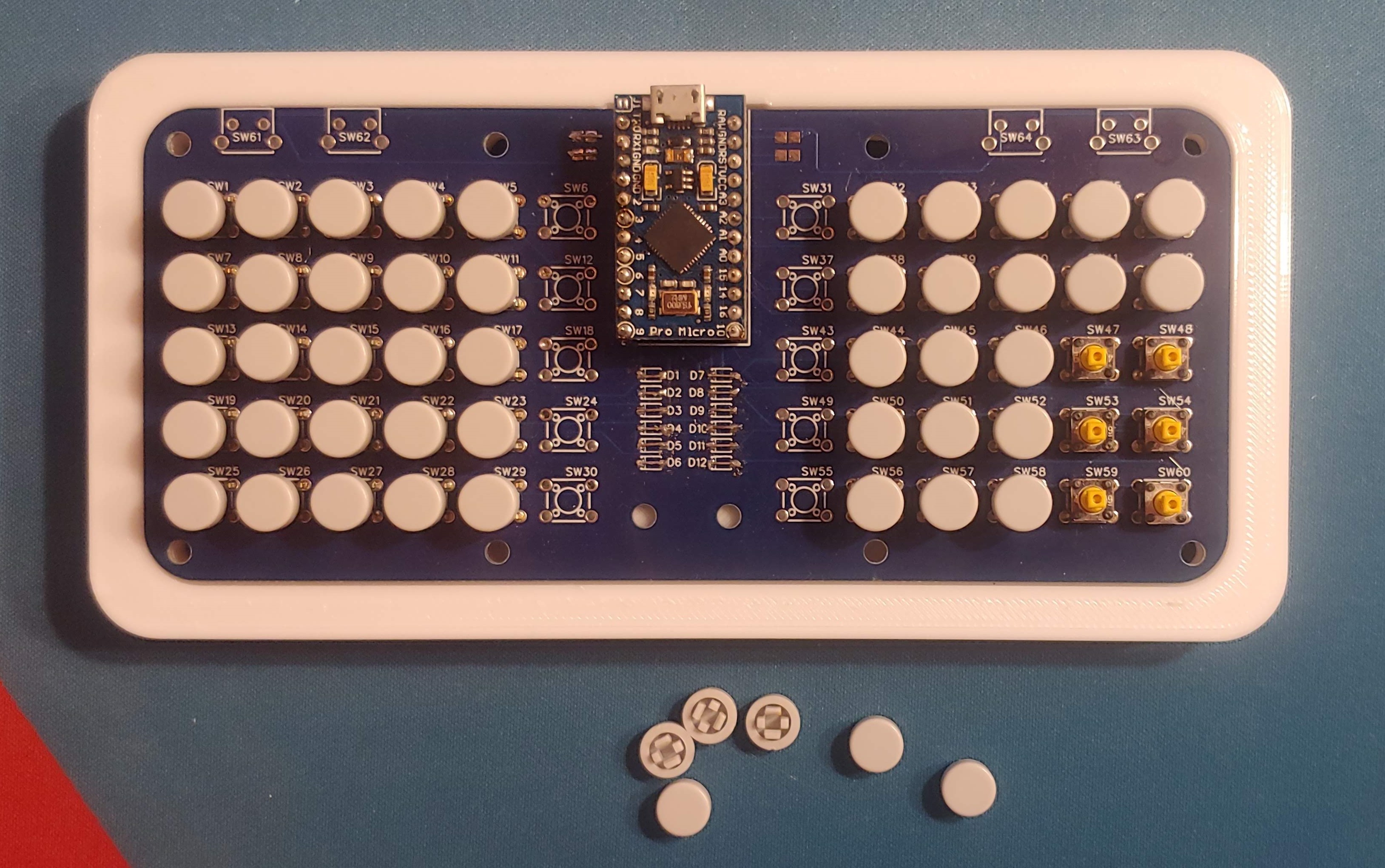
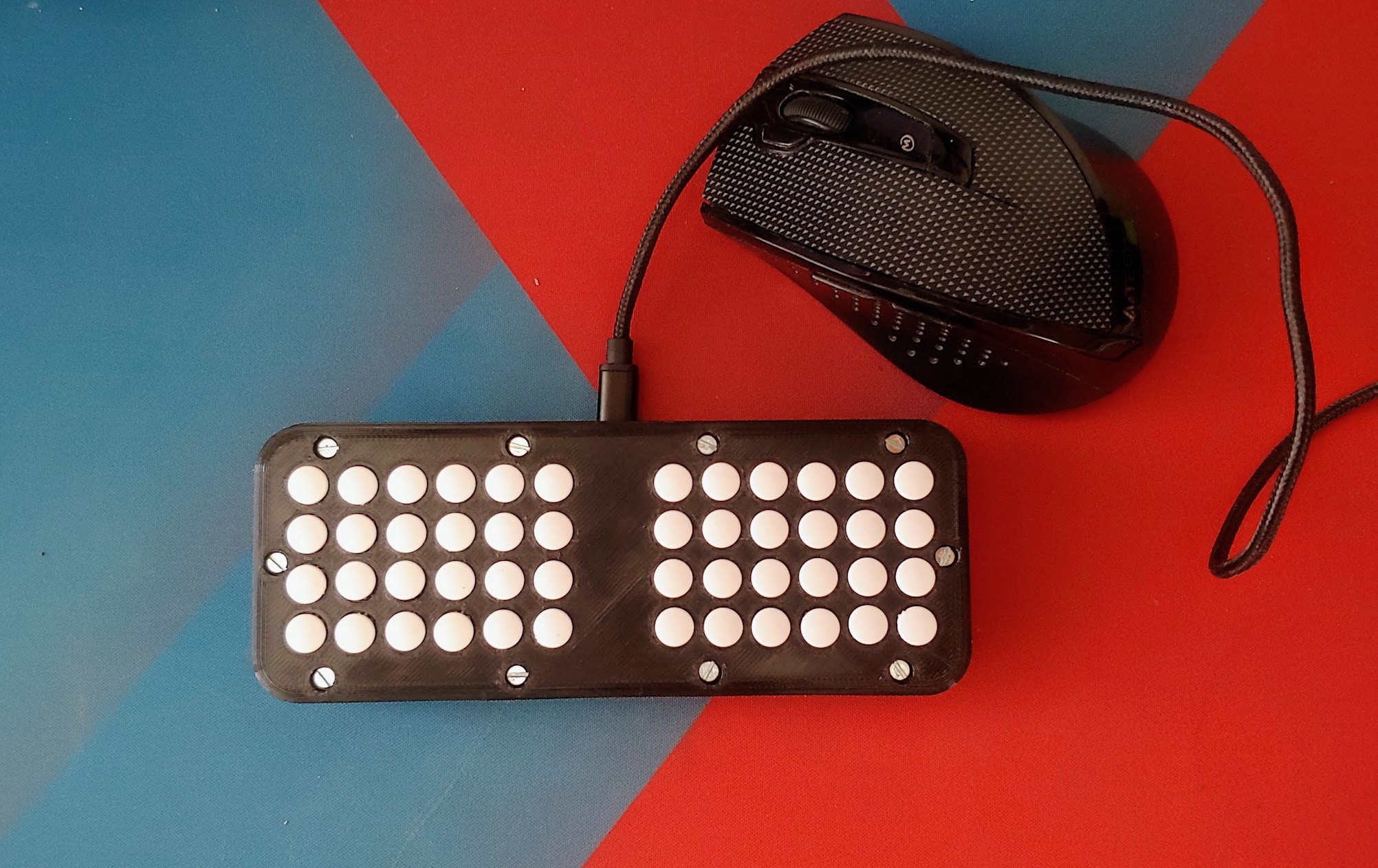
---------- more ----------First of all, I updated the PCB design. I reduced the number of mounting points for the main face buttons—now the board can accommodate 5x5x2 = 50 tactile switches. I also added space for 6 corner buttons for the bumper keys, and I connected a thumbstick to the remaining two analog pins.
![]()
![]()
![]()
This time, Amber from Elecrow helped me with the PCB fabrication. A huge thanks to Elecrow for their support! Elecrow offers hobbyists 2 layer PCBs up to 10x10 cm for just $1!
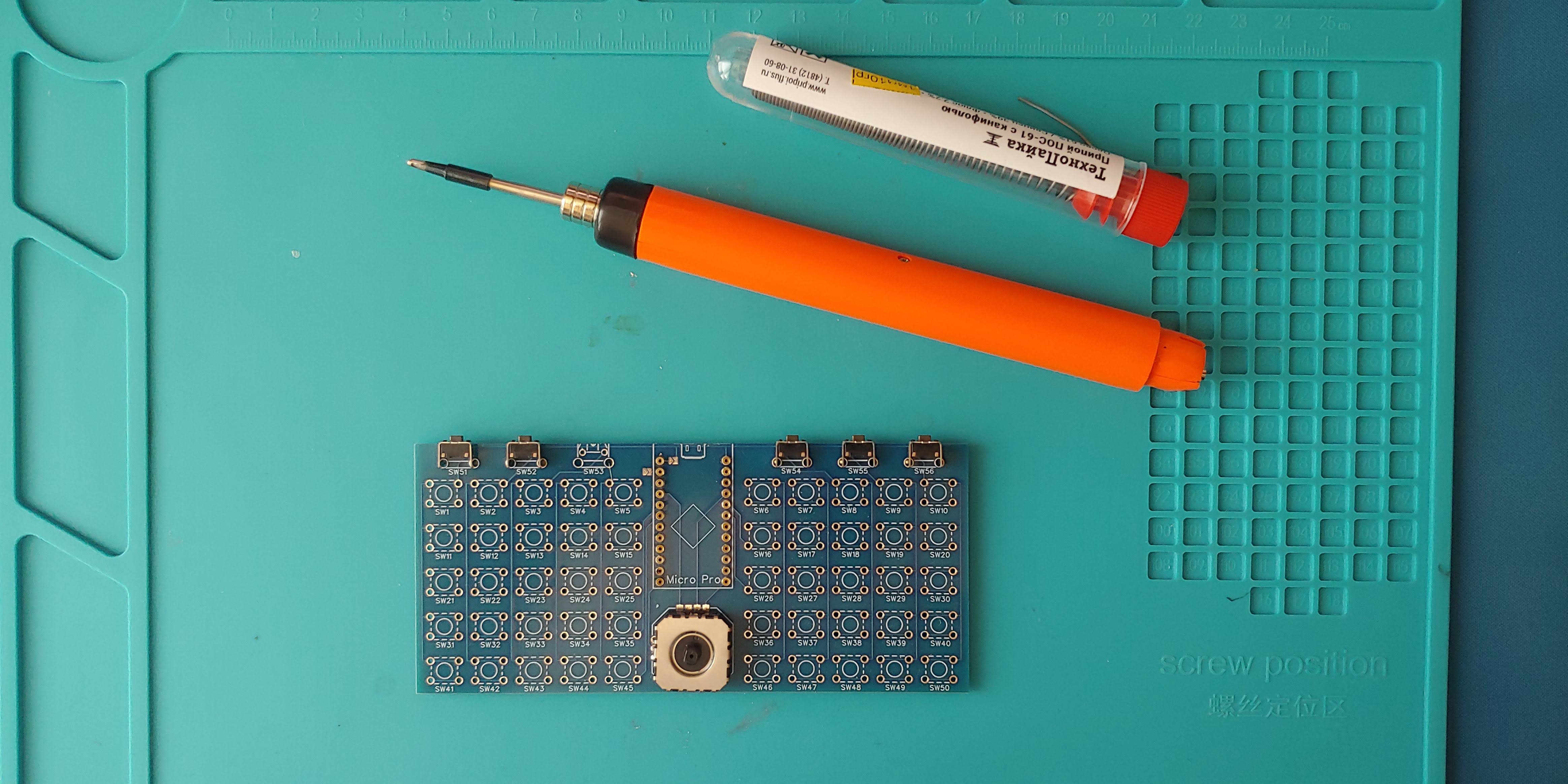
![]()
![]()
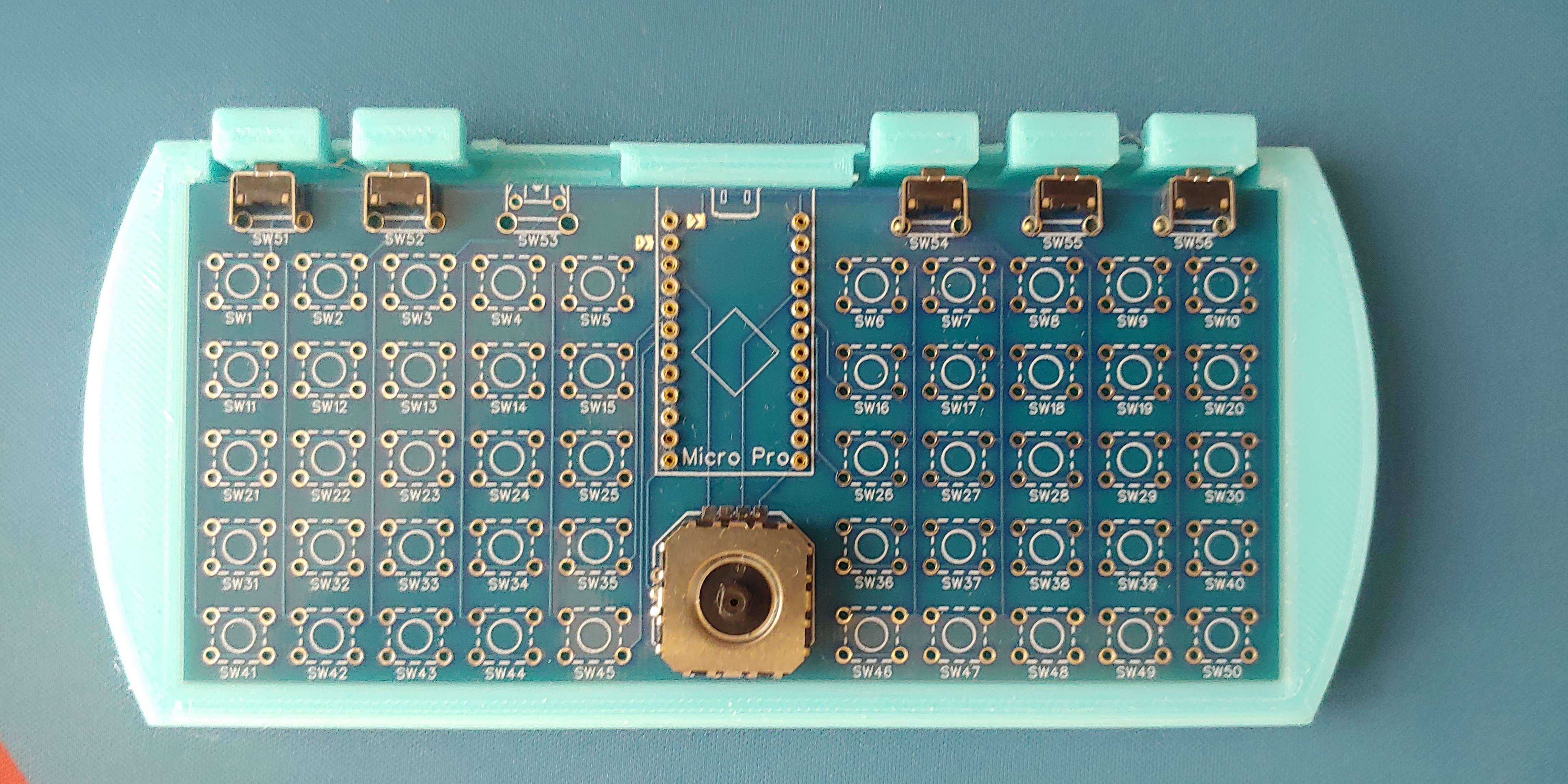
The 3D-printed bumper keys turned out to be quite fragile—one even broke when I was removing the supports. No big deal though, since I only have five corner buttons! On the bright side, the bumpers feel pretty good to press.
![]()
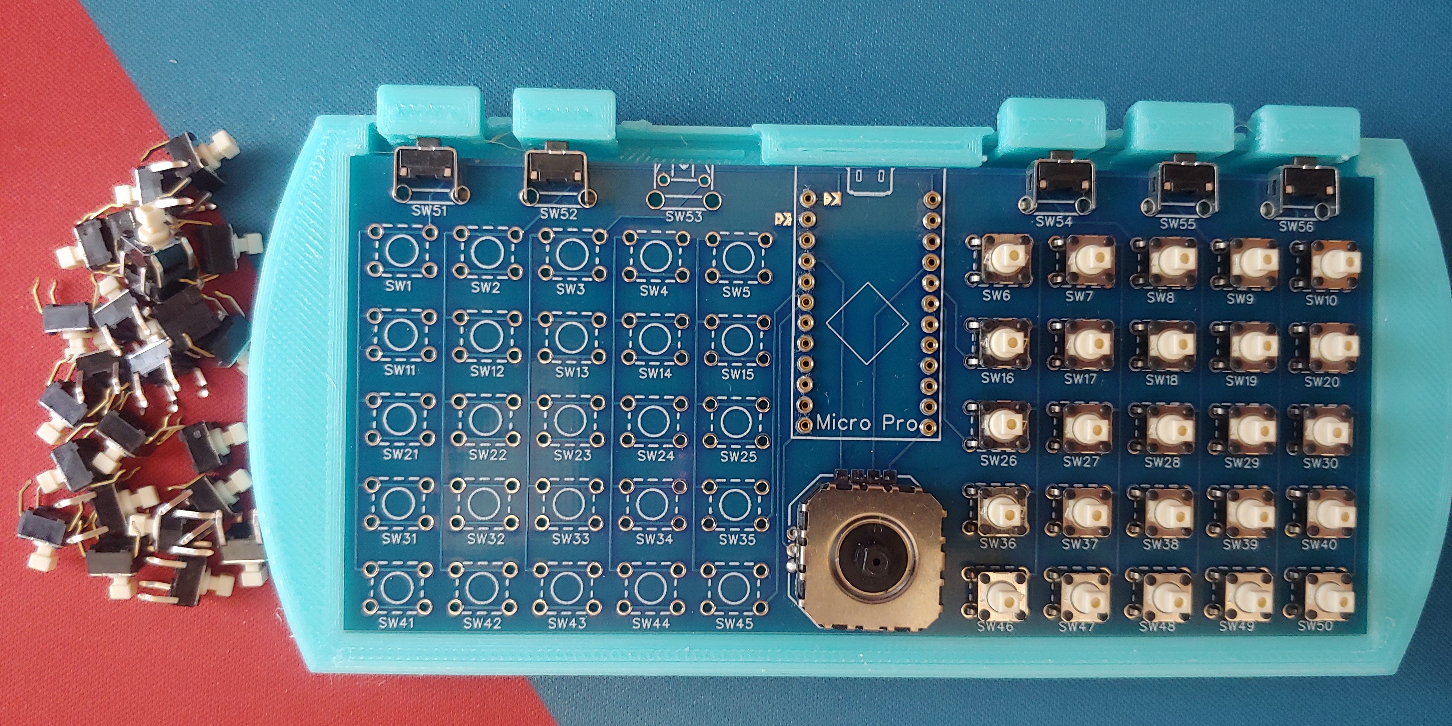
I decided not to solder the tactile switches but simply inserted their legs into the mounting holes. The legs are springy enough to maintain electrical contact without the need for soldering.
![]()
![]()
Unfortunately, the PSP joystick cap didn’t fit the thumbstick I installed on the board. I’ll need to 3D-print a custom cap for it.
![]()
![]()
![]()
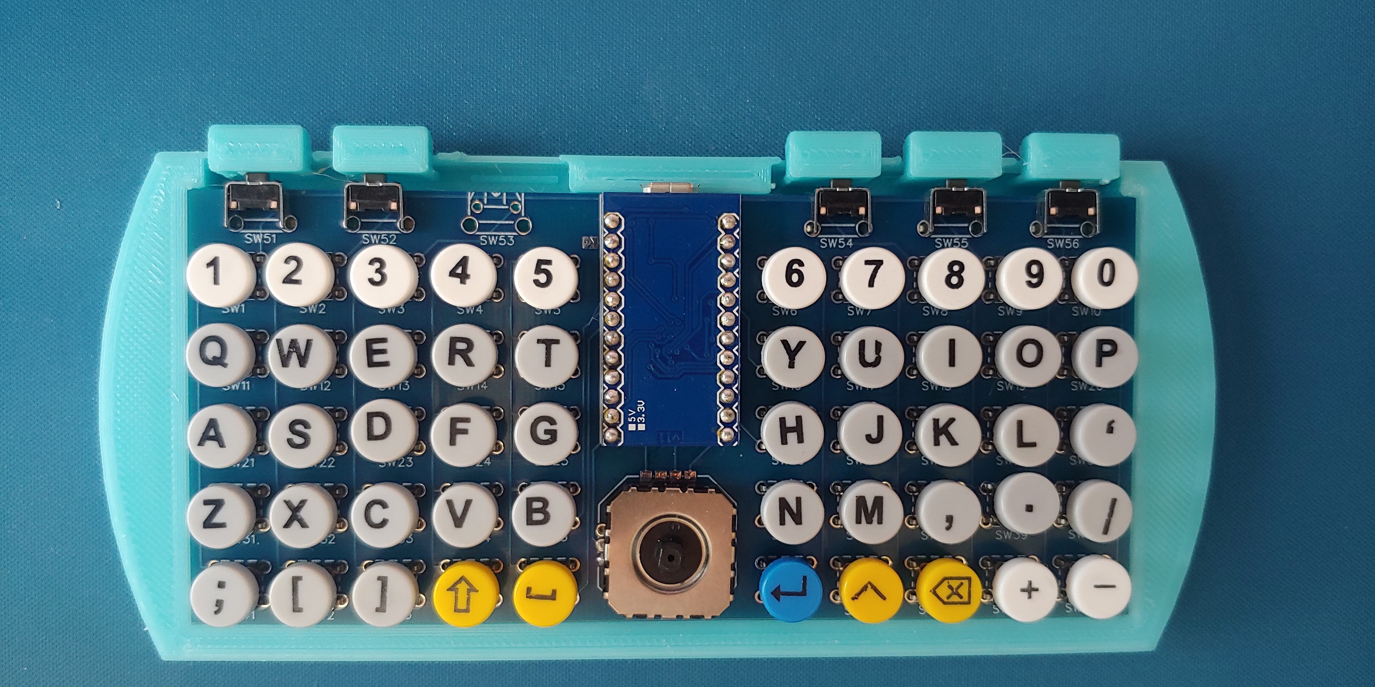
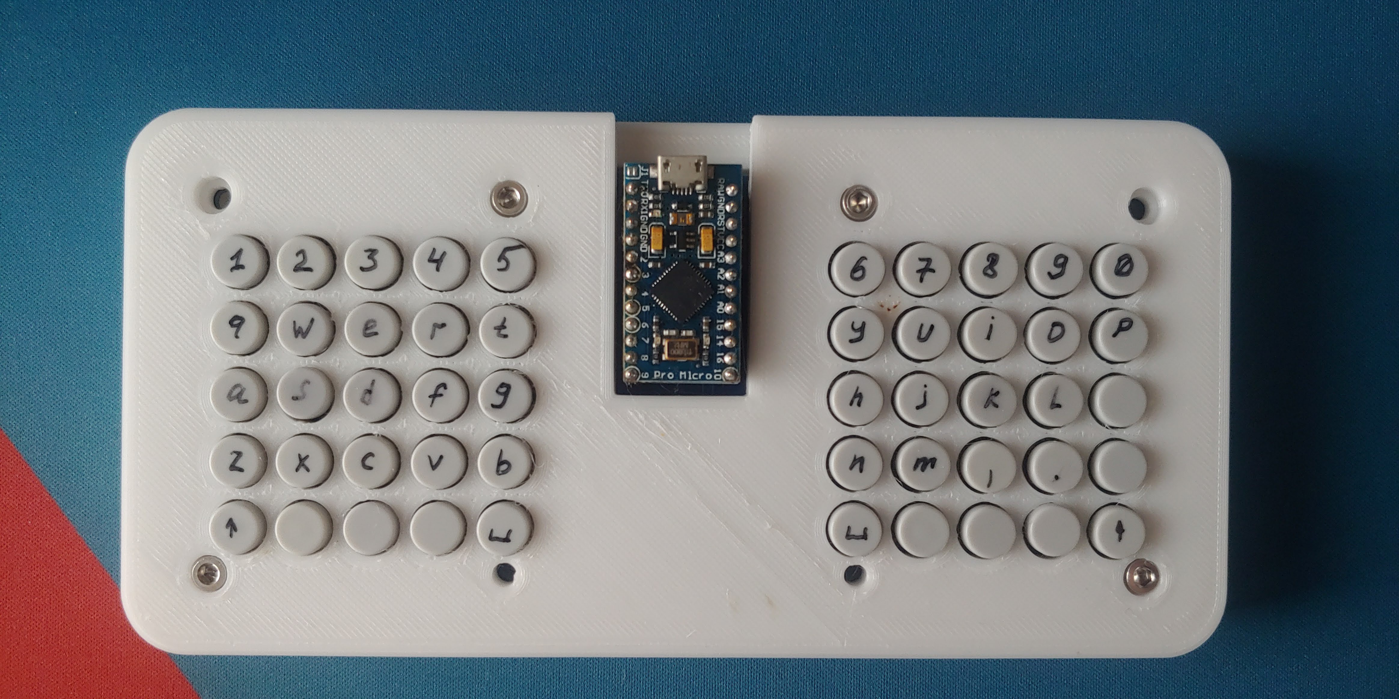
I tried my hand at Typing Racer on my custom keyboard. My current speed is 18-22 words per minute. How much do you think I can improve that?
-
Making FinchBoard Legendary: Printing the Custom Legends
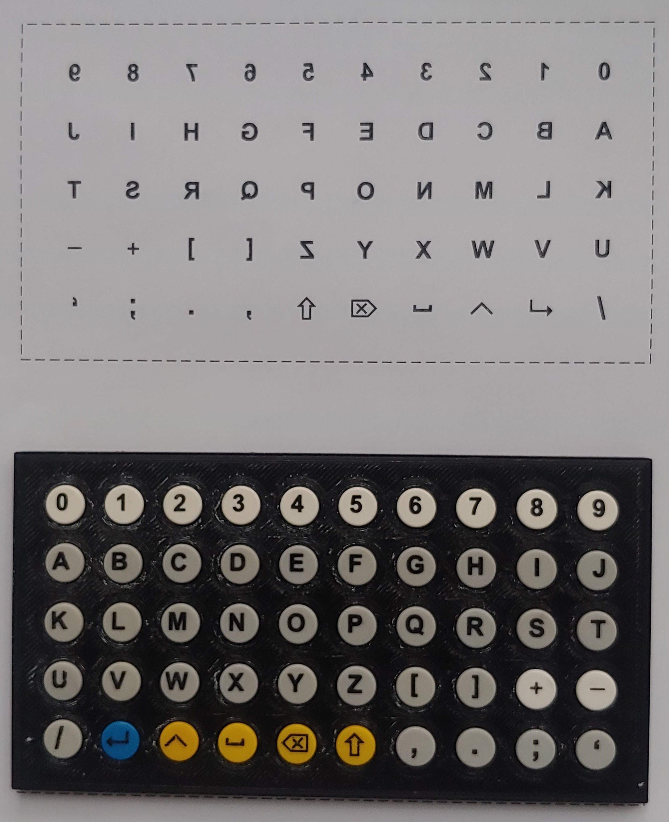
07/14/2024 at 14:24 • 0 commentsOn a full-size keyboard, I can type using blank keys, but the FinchBoard is a different matter. Sure, I could memorize the layout or write it on the keycaps with a permanent marker, but I wanted something more aesthetically pleasing.
Since I couldn’t find suitable keycaps with lettering on the market, I came up with the following solution.
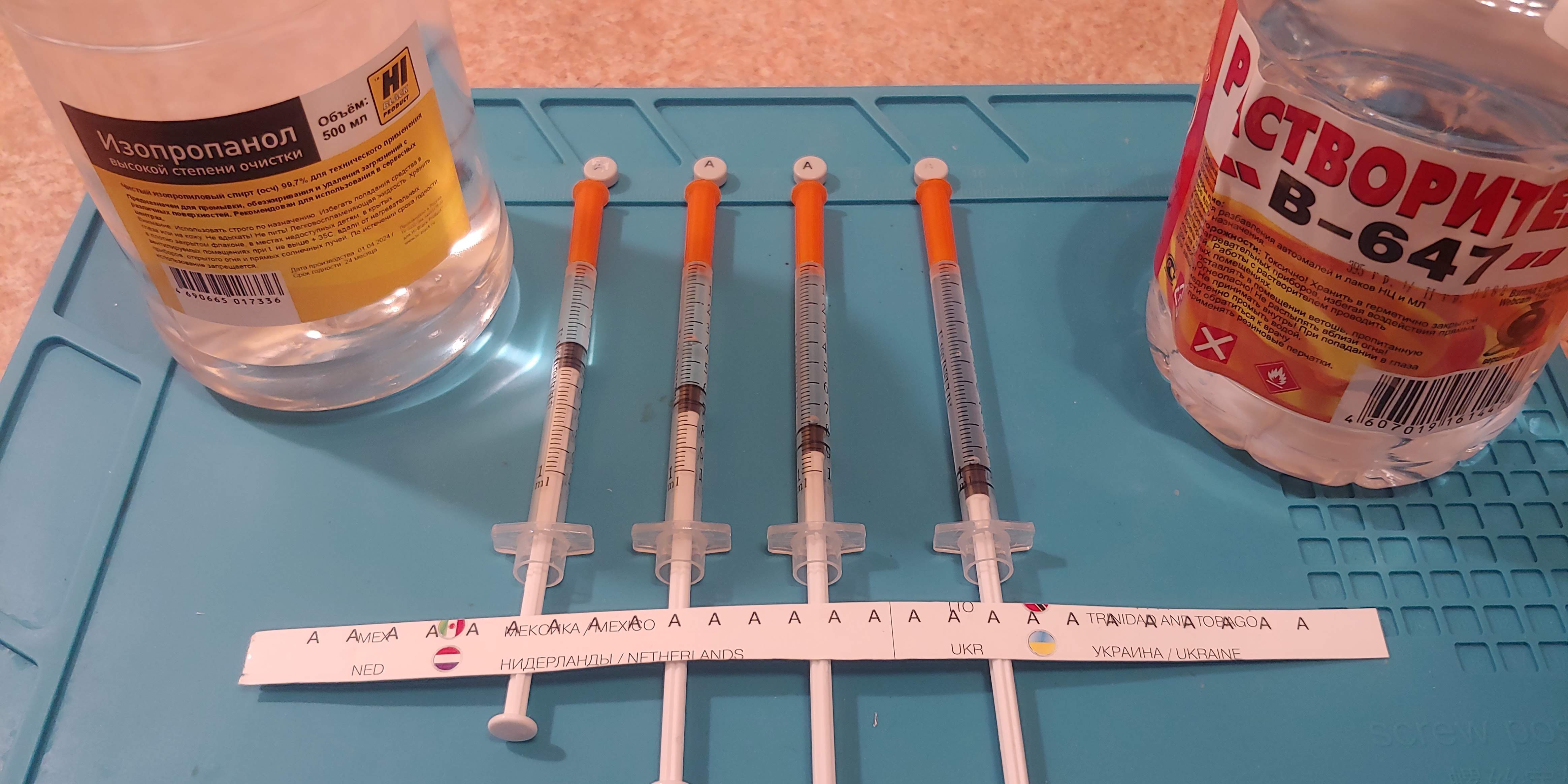
Using a laser printer, I print the letters onto a sheet of glossy magazine paper and use solvent to transfer the toner to the surface of the caps. The keycaps are made of ABS plastic, which becomes soft at 100°C and melts at 300°C. They dissolve well in acetone, and the 647 solvent I use dissolves the caps to about the same extent as acetone.
---------- more ----------Through trial and error, I managed to find the appropriate solvent composition.
![]()
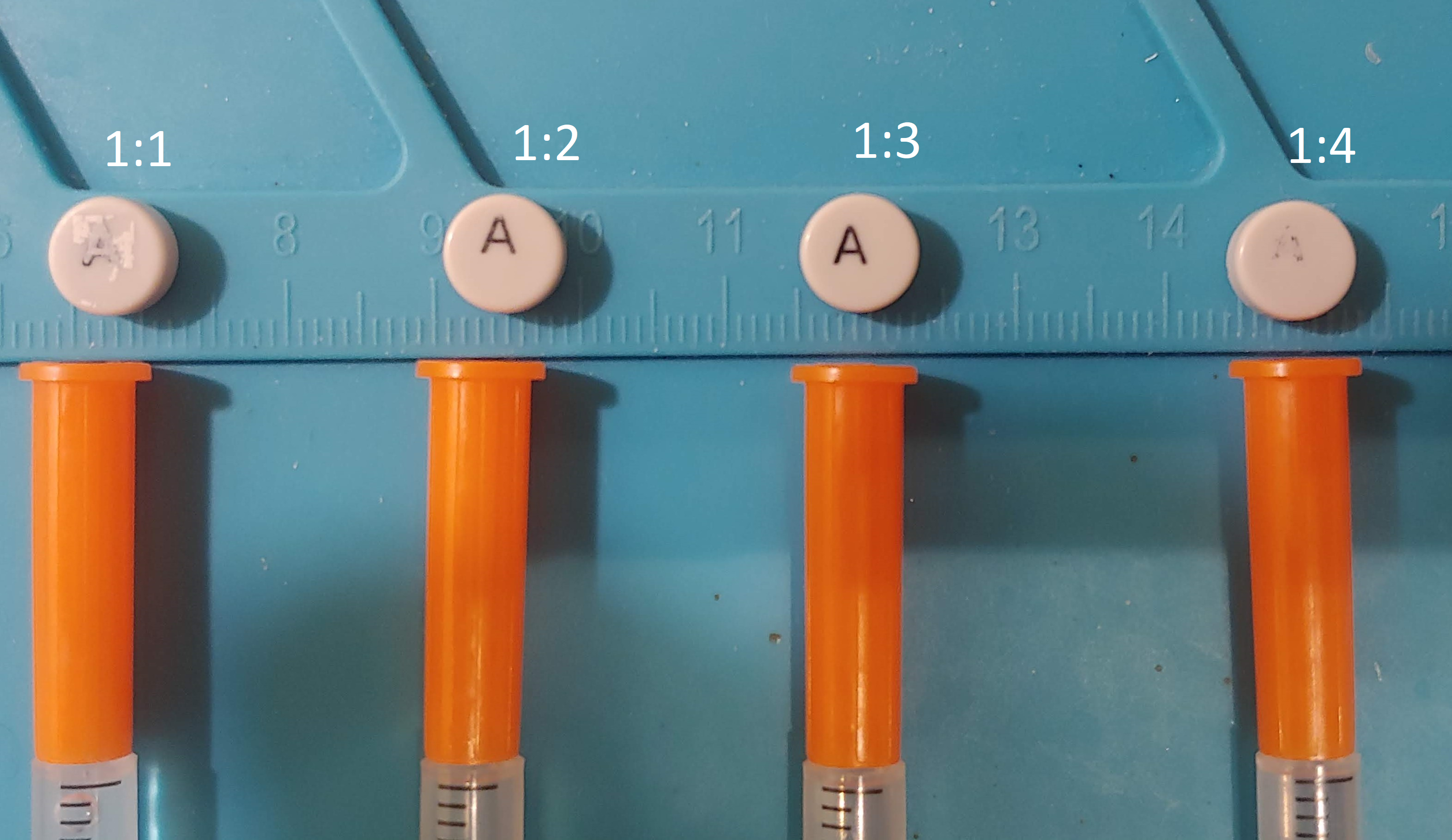
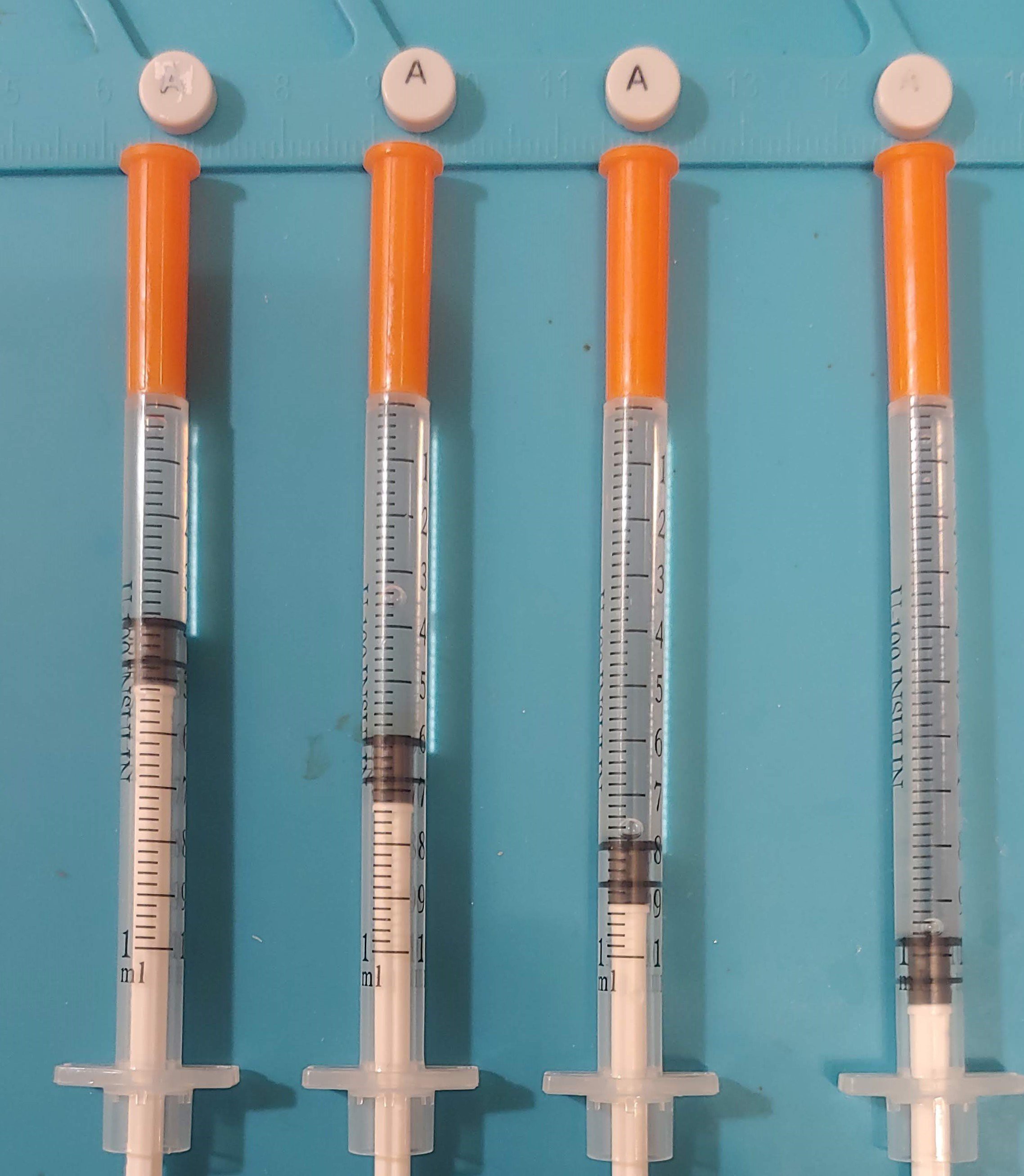
I mix solvent 647 and isopropanol in a ratio of approximately 1:2 or 1:3
![]()
![]()
I found that a mixture with a higher concentration of solvent, such as 1:1, makes the image blurry, while a 1:4 concentration is too weak to transfer the toner. A 1:1 mixture of acetone and isopropanol also works for transferring toner.
To position the patterned paper and the caps, I printed a cap holder and a lid with 2mm thick rubber glued inside as a press to evenly distribute pressure on the caps.
![]()
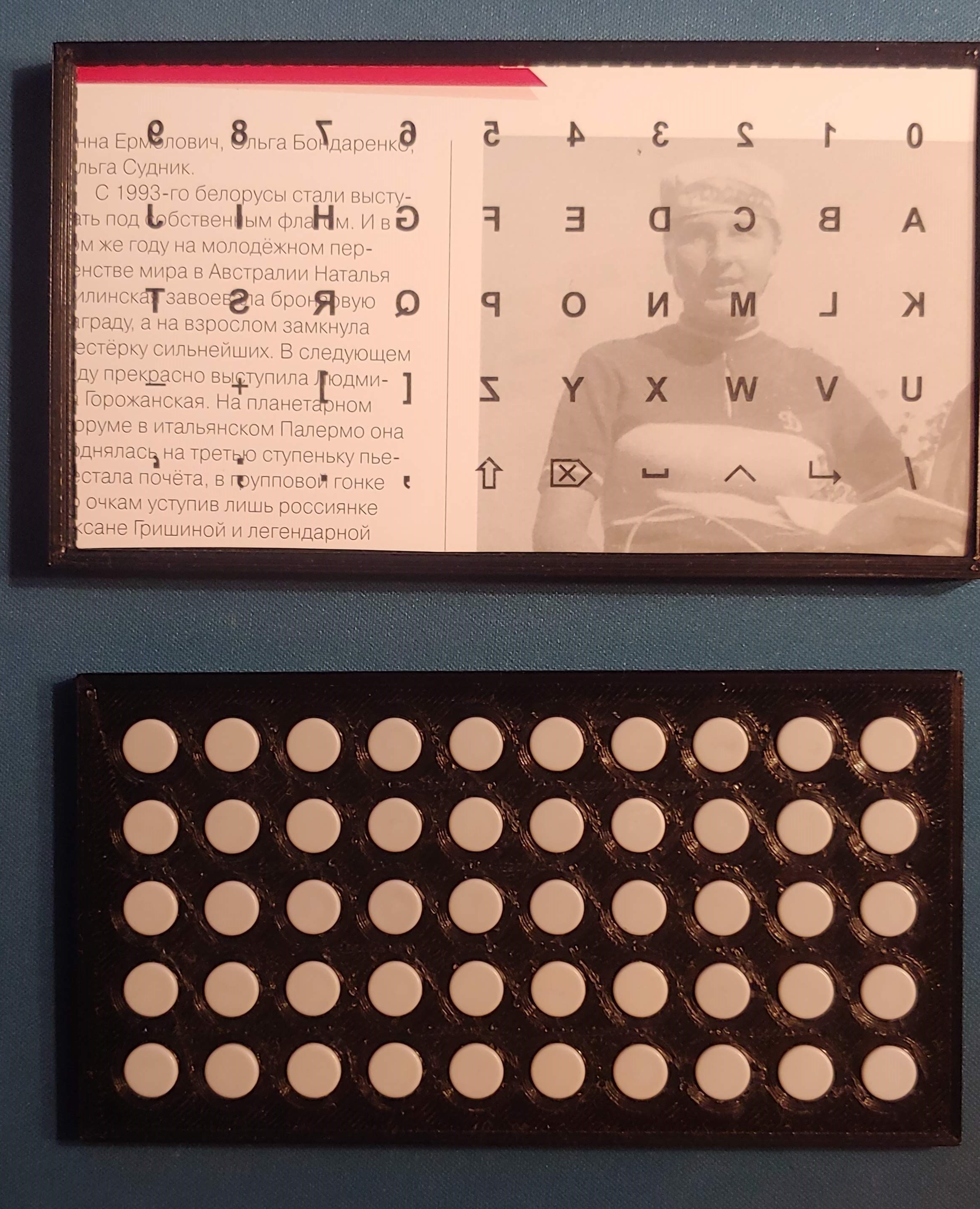
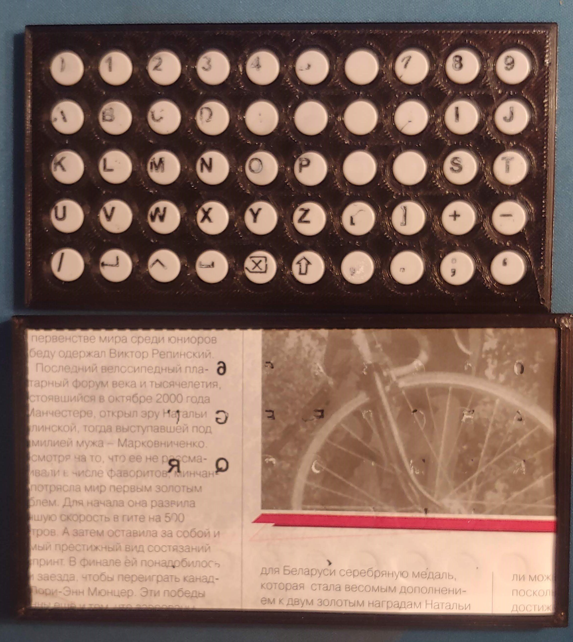
I prepared a layout in CorelDraw, remembering to mirror it before printing.
![]()
First, I cut out the layout along the outline and placed it on the rubber inside the lid. Then, I moistened it with solvent using a syringe and placed the holder with the caps on top. To apply pressure, I initially tried pressing them with my palm on the table, but the result was poor. Using my body weight gave better results:
![]()
Finally, using a vice provided a complete transfer of the toner from the paper to the caps.
![]()
The position of the letters was a little off, so I corrected the layout in CorelDraw.
![]()
As for the durability of the images transferred this way, I’m not entirely sure yet. They don’t rub off with a finger and are resistant to alcohol when gently wiped. However, if you soak the toner with alcohol and rub it forcefully with a napkin, the image can be erased. I think it makes sense to cover the caps with a layer of varnish. An alternative to varnish could be to paint the caps with sublimation paint and then remove the toner, which should leave the plastic under the toner with its original color.
-
I assembled a prototype on a PCB from PCBWay
01/29/2024 at 11:40 • 0 commentsIt's been quite a while, but I have some updates to my project.
First, a big thanks to PCBWay for providing me with high-quality PCBs for this project!
![]() ---------- more ----------
---------- more ----------I managed to put together a prototype keyboard that is significantly better than my first attempt. This time, I used Omron B3F-1052 switches, which are much better than the ones I used previously. Using the right PCB is also much easier than running thin wires on a prototype board.
![]()
I settled on a 5x5 key layout for each hand, which now seems optimal to me. I'm considering adding the missing functions using layers.
![]()
I continue to learn to type on this keyboard, and I can say that it feels pretty good in the hands. I was concerned that the clicking of the switches would be bothersome, but so far, this has not been an issue.
I also want to work on the keyboard layout. The classic "QWERTY" layout seems extremely suboptimal for typing with two thumbs. I aim to keep finger movements to a minimum and learn to touch-type on a new layout.
After soldering the switches to the board, I found that they hold up well on their own because their legs spring slightly in the mounting holes. This opens up the possibility for quick switch replacements, which is useful considering that branded switches are surprisingly expensive.
I also have some ideas on how to 3D print shoulder buttons.
-
First try
07/12/2022 at 13:32 • 0 commentsFinally, I’ve created something that I can actually use to get a feel for the project.
![]()
It looks like the cheap switches I used are problematic; they feel inconsistent, with some being clicky and others mushy. There might also be issues with the keycaps or the case contributing to this.
My plan is to learn how to touch type on this keyboard. Perhaps I should put tactile marks on the keycaps to help with this.
![]()
FiNCH: Thumb Keyboard
A compact, handheld ortholinear keyboard with tactile switches. Hardware customizable and fully programmable with QMK firmware.