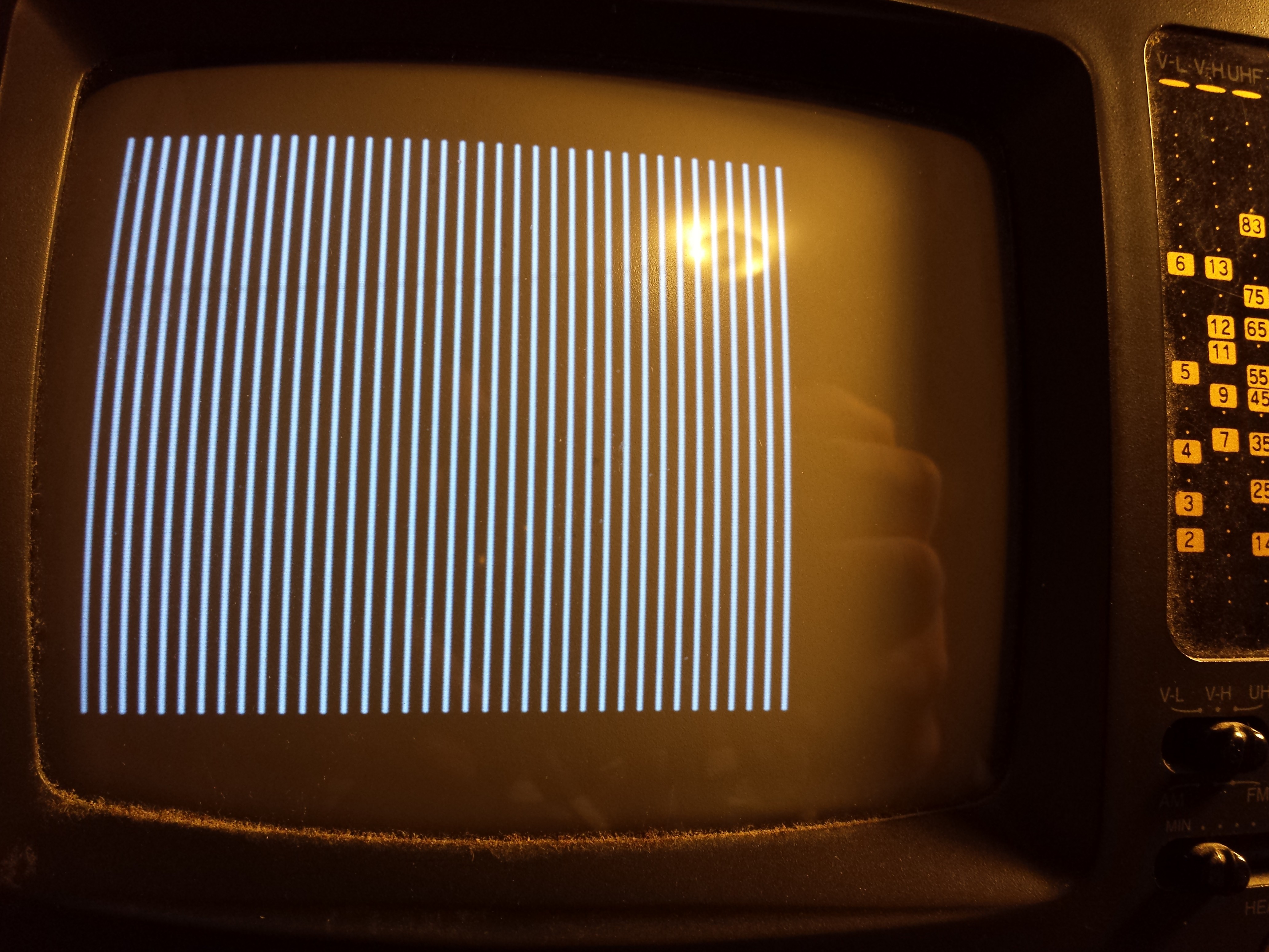
I spent some time online researching how NTSC video signals work. There are a lot of details, and after attempting to implement the full odd/even interlaced signal complete with equalization pulses and 1/2 scanlines, I ended up with a picture that was slightly unstable on my LCD monitor. I got an old B+W portable TV, and that refused to synchronize to my signal at all. Oh well.
After some more searching, I found this page: http://www.rickard.gunee.com/projects/video/pic/howto.php Rickard's approach started by experimenting with Horizontal syncing only. This didn't seems like something at would work on my LCD monitor: its want a full frame before it displays. Using the old CRT TV, I hacked my code down to horizontal sync only. And it displayed a rolling picture, that was horizontally synchronized! If I messed with the v-hold setting on the TV, I could get a very slow roll. All I need it a little vertical synchronization.
I decided to implement the only part of vertical sync that looked unique: The vertical serrations. During the vertical serrations, two things happen: A) The sync signal rate is double (2 sync periods per line) and B) The signal is inverted: Normally low instead of normally high. This made the B+W TV sync just fine.
But I don't have a 1/2 scanline anywhere, and I was sure the picture wasn't being properly interfaced odd/even. After a little more research, I discovered this is what the Atari 2600 does: Every frame is even lines only. It turns out many game console do this, and it's referred to as '240p'. If you search for this you will find a lot of new TVs won't even show anything on this mode.
Stella (Atari) programming Guide: http://atarihq.com/danb/files/stella.pdf "A typical frame will consists of 3 vertical sync (VSYNC) lines*, 37 vertical blank (VBLANK) lines, 192 TV picture lines, and 30 overscan lines. Atari’s research has shown that this pattern will
work on all types of TV sets."
After getting this working, I found the TV image was a little jittery in the horizontal direction. I guessed that this was the 8Mhz internal oscillator. I had a piece of e-waste with a 10.752 Mhz crystal oscillator in it, so a salvaged it and updated all the constants in the code to run at 10.8 Mhz. Now the picture is solid.
I am using 350 bytes to produce the above image. Let's see if I can squash a game or two into the rest of the space.
I noticed someone else is attempting full-color space invaders. I better try something different :-)
 Mars
Mars
Discussions
Become a Hackaday.io Member
Create an account to leave a comment. Already have an account? Log In.