makeTVee
-
Resin printed diffusors
10/16/2022 at 11:57 • 0 commentsStarted experimenting with resin printed diffusors, using clear resin. Looks promising:
![]()
-
Power supply
08/08/2022 at 10:45 • 0 commentsThe earring was designed around the 1254 Li-Ion battery which is a good fit between size (12mm diameter, 5.4mm thickness) and capacity (around 40-60 mAh depending on manufacturer). First tests with a LIP1254 showed two major issues, the battery capacity was way lower then expected when discharging the battery with 5-6mA and the voltage was dropping way to fast under 3.6V which was below the forward voltage necessary for blue LED on the WS2812. So after approx. 10-15 minutes, only the red and green LED light up. Not sure what caused this behavior, maybe the cells where already quite old or discharged deeply.
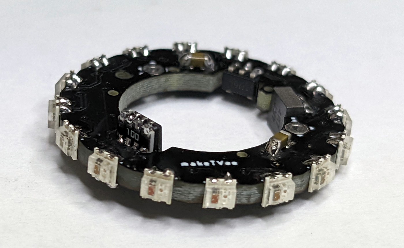
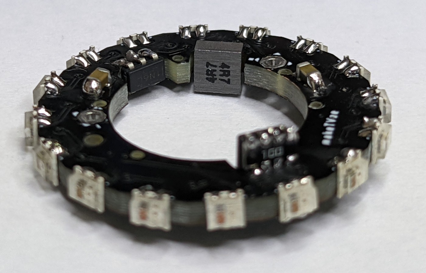
The solution for the voltage dropping was adding 3.6V boost converter TPS613226ADBVT to the ring. This boost converter and the necessary inductor are mounted on the inner edged inside matched cut out areas.
Because the battery didn't worked like described in the datasheet, it was replaced with a more expensive Varta CP1254 which not only fulfilled the datasheet spec and lasts more than 5 hours@5mA, but also showed a much lower voltage drop so it has to be tested, if the boost converter is really necessary and useful for the next revision. Also other cells from different sources will be tested in the near future to find alternatives.
Main issue after using the earring ist the missing battery protection on the coin cell. You have to be very careful to not shorten the battery when exchanging it, because this immediately heats up the cell to a non-touchable state. It's pretty obvious, that this has to be fixed before publishing any files for the project.
-
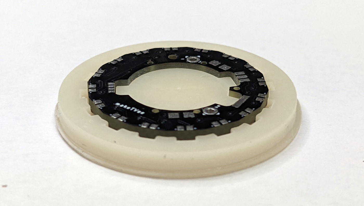
PCB and assembly
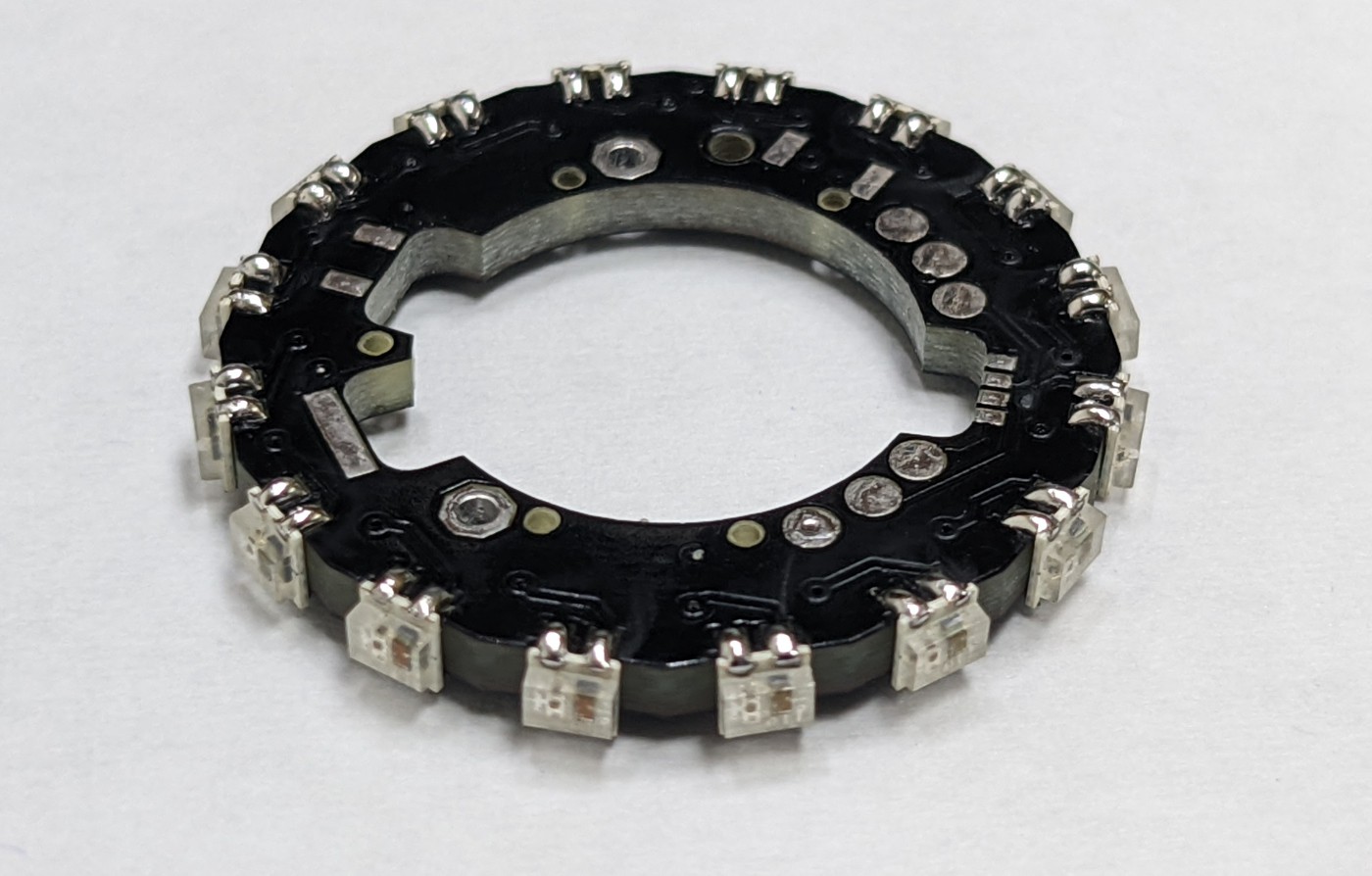
07/19/2022 at 15:06 • 0 commentsThe PCB has a center hole and some cutouts for the components.
![]()
The LEDs are placed first using a resin printed jig. Matching holes are holding the LEDs in place while soldering one side to the PCB.
![]()
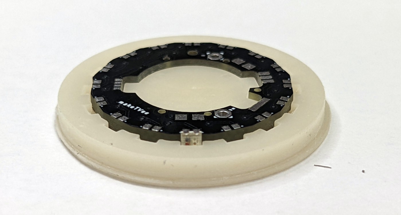
When all LEDs are soldered to the top
![]()
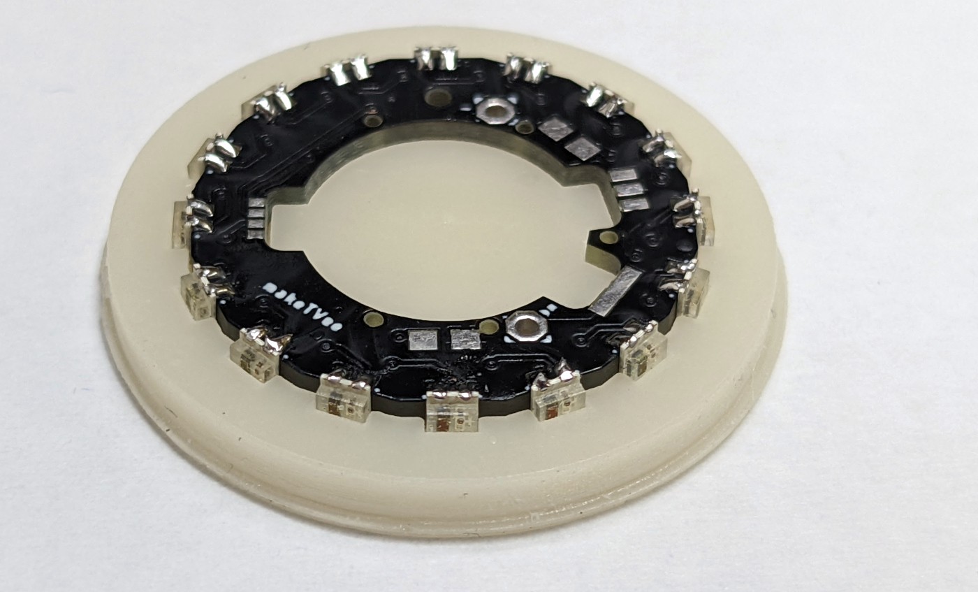
the PCB is removed from the jig and the bottom side is soldered.
![]()
The ATtiny 45 is solder in a notch of the PCB in 90° orientation by using two resistor nets (10 Ohm), one per side.
![]()
The booster converter with the inductor are also solder 90° with corresponding pads on top and bottom layer. If the battery voltage drops below 3.6V, the blue LEDs of the WS2812B stop working, therefor the booster is used to ensure a proper voltage level.
![]()
WS2812B (Neopixel) Earring
Earring with 16 addressable LEDs (WS2812B-2020) and rechargeable coin cell battery.