Evan
Evan-
Attempting to tune the touchscreen controller
10/19/2022 at 06:32 • 0 commentsFor reasons documented in a previous log entry, I am using the GT9110 touchscreen controller from Goodix. (Essentially, this is the only suitable touchscreen controller I could find in a footprint that I could actually use without spending hundreds of dollars per PCB revision.) In a later log entry, I got the GT9110 and Linux talking to each other.
Goodix is quite a frustrating company to buy from as a hobbyist. In comparison to some chip manufacturers like TI, who publish loads of documentation about their chips on the internet, Goodix is very stingy with their documentation. As far as I can tell, there's no way for hobbyists to get the documentation except hoping to find a leaked datasheet posted online somewhere. When you do find a datasheet, it's not particularly helpful. Some guidance on how to tune your touch panel (rather than just a table of registers with ~5 words about each) would be nice.
![]()
Goodix being extremely unhelpful to someone trying to design a board with their touchscreen controllers. Maybe I'll try reaching out to whatever AliExpress vendor I bought these chips from. I doubt they'll have the documentation, though.
Trying to tune the touchscreen controller
So I had the touchscreen detecting my touches, but it also detects phantom touches; mostly along a vertical line a quarter of the way in from the right side of the screen.
To recap how capacitive touchscreens work: The screens contain two layers of transparent traces, typically made of ITO, a transparent conductor. On one layer, you have traces going across the screen horizontally; in the other layer, traces go across the screen vertically. (This website has a pretty good graphic explaining this.) The touchscreen controller will send a signal to each "drive" trace (in my case, horizontal) and measure how much of this signal capacitively couples to each "receive" trace (vertical). When you bring your finger near the screen, some of the signal from the drive line will couple to your finger instead of the receive lines, which makes a measurable difference in coupling.
I have a few hypotheses as to what might be happening:
- That channel might have a bad connection on the board
- The chip itself might have a fault on that channel
- That channel might be receiving EMI from some nearby components, either on the PCB itself or in the touchscreen/LCD panel. Potentially this could be crosstalk between the transmit and this receive trace.)
I got a hold of a programming guide for the GT911 (the little sibling to the GT9110 -- same family, but fewer channels. I bet it's the exact same silicon die inside.) This gives me information on the i2c register maps.
(Aside: Apparently these chips support a mode called "HotKnot" in which two touchscreens can transfer data to each other!?!? What a bonkers feature.)
These are the registers which seem relevant to tuning sensitivity:
Address Name Notes 0x8053 Screen_Touch_Level This seems to be the signal level threshold above which a touch begins to be reported. Higher numbers = less sensitive. 0x8054 Screen_Leave_Level This seems to be the signal level threshold below which a touch stops being reported. Higher numbers = less sensitive. 0x806b Pannel_Tx_Gain The lowest 3 bits set the DAC gain, where 0 produces the largest signal and 7 producest the smallest signal. 0x806b Pannel_Rx_Gain The lowest 3 bits set the ADC gain. It seems like 7 is the most sensitive and 0 is the least sensitive. 0x806d Pannel_Dump_Shift Setting the lowest 3 bits to N > 0 will cause the touch signals to be shifted by N bits left. This would be useful if I wanted even more receive gain than Pannel_Rx_Gain can give, but I want less. I'd like to be able to overwhelm any noise by cranking the Tx power up and decreasing the RX sensitivity. Unfortunately, the configuration I had started with was already using 0 for the ADC and DAC gain, so it was already producing the strongest signal with the least Rx amplification.
Other registers
I have played with some other registers:
Address Name Notes 0x8062 Drv_GroupA_Num The 5 lowest bits on these two set the number of channels used on each transmitter group. There are 42 total transmit channels available, of which I'm using 40. By setting these so they total 40 instead of 42, my panel became a bit better-behaved and also got rid of a gap at one end of the screen. Drv_GroupA_Num has a flag "All_Driving", and Drv_GroupB_Num has a flag D_Freq; I'm not sure what either of these do. 0x8063 Drv_GroupB_Num 0x8067 Pannel_BitFreq_L These configure the fundamental frequency of the clock driving GroupA and GroupB. 0x8068 Pannel_BitFreq_H 0x8065 FreqA_factor These act as multiplication factors on the fundamental frequency. 0x8066 FreqB_factor When I tried out different driving frequencies, I either saw no improvement or a drastic deterioration of touchscreen function.
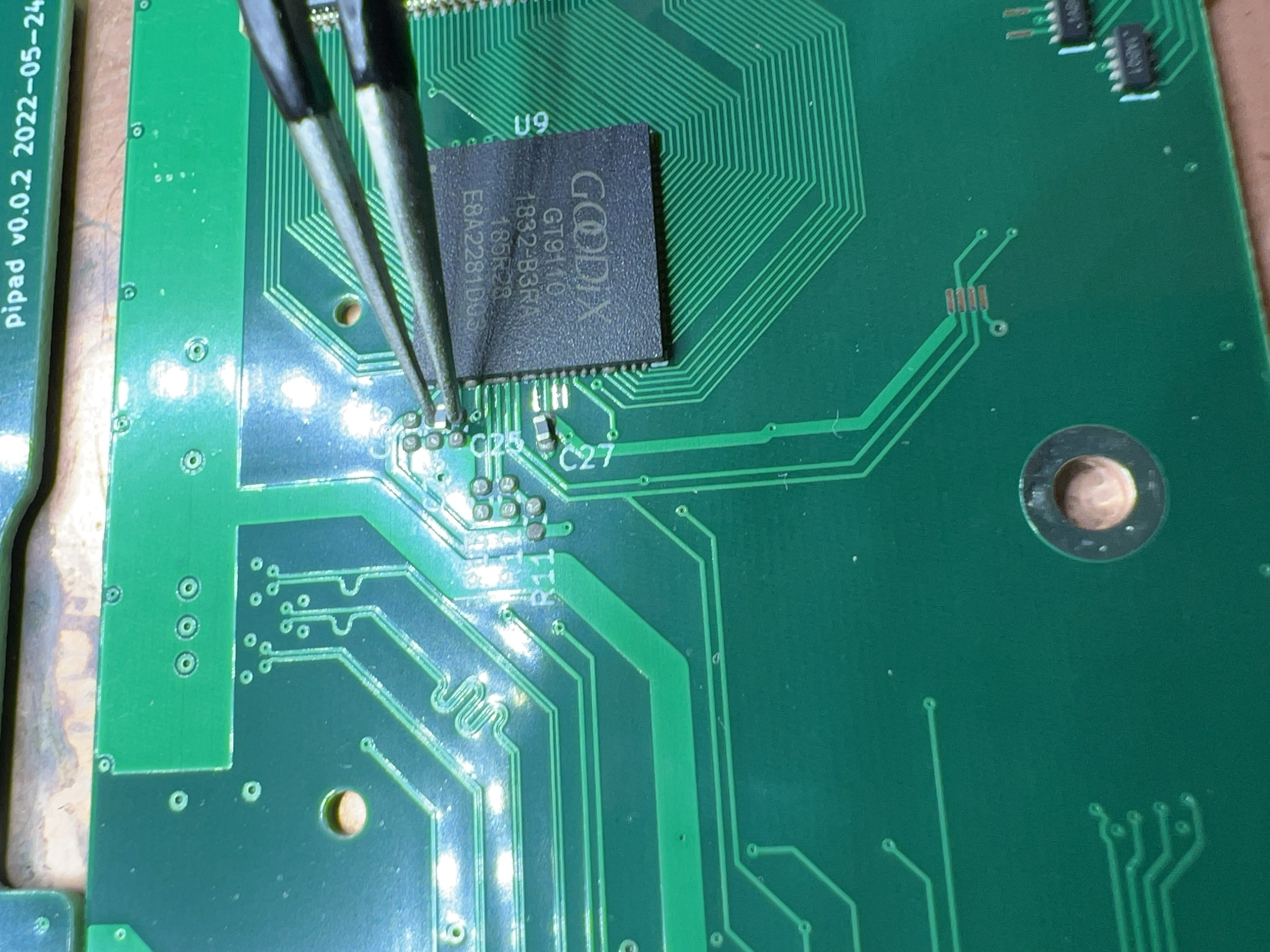
As for a faulty channel or bad connection on the board: I've already tried re-reflowing the flat flex connector, which had no effect. Perhaps I should take a look at the GT9110 chip itself under the microscope and make sure all the pins are well-soldered. (If there's a running theme with this project, it's that I keep discovering pins which aren't connected properly.)
-
Trying my hand at driver development
10/18/2022 at 07:18 • 0 commentsOne issue which contributes to the backlight flicker is the undervoltage protection (UVLO) feature of the TPS61177A. This is configurable over i2c, but defaults to 3.5V, which is pretty high.
In order to set this at startup, I decided to try and write a kernel driver for the TPS61177A. I partly followed https://docs.kernel.org/i2c/writing-clients.html and partly cargo-culted some stuff (mostly related to regmap) from the sn65dsi83 driver. (I've poked around in that driver in previous debugging sessions, which helps me understand its structure more than some other random i2c device driver.)
The driver essentially just sets the 0xa2 register to the value 0x02, which corresponds to a UVLO voltage of 3.0V. (Ideally, they'd have options between 3.0 and 2.55, but alas...)
After a few hours of struggle, I got this to configure the UVLO voltage over i2c, but I've run into a hardware-level problem with this approach: in order to save GPIO pins, I used the same GPIO for both the sn65dsi83's enable pin and the tps61177a:
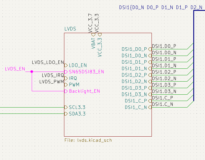
![]()
Screenshot of part of my schematic, showing that the enable pins for the LVDS bridge (sn65dsi83) and backlight driver (tps61177a) are shorted together. This means that the drivers for both chips are competing for control over the GPIO pin; this seems to cause the second driver to fail to load. (In this case, the sn65.)
There's an easy workaround, for now: I can manually tell the tps61177a to save its configuration to EEPROM. Long-term, I'd like to reduce the number of manual steps that someone would have to take in order to get this board working, and that means either a driver like the one I've written, or some userspace solution like a startup script.
-
Backlight flickering investigation + device tree overlay for the battery charger.
10/16/2022 at 07:36 • 0 commentsI've been investigating the backlight flickering that I showed in my previous log entry. My main hypothesis was that the long wires between my breakout board and my main PCB were adding too much inductance, causing increased ripple. I had moved an input decoupling capacitor to the breakout board, which helped some but didn't entirely solve the problem. Adding more capacitance on the input side didn't help much more.
One thing I noticed is that the problem drops entirely when the tablet is connected to the charger. This made me suspect that maybe my battery is the problem.
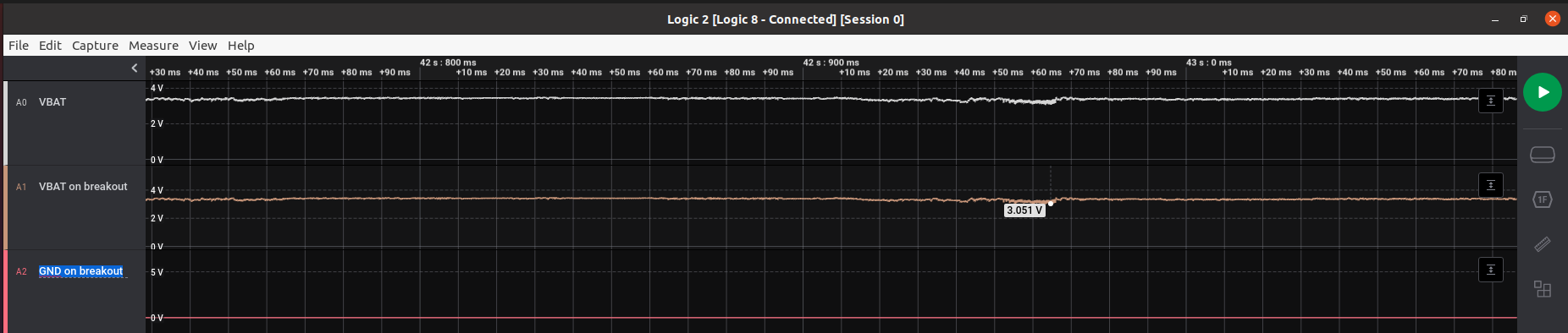
![]()
Looks like there isn't much difference between the VBAT measured at the battery terminals and VBAT measured on the breakout board (at least at speeds the Saleae can measure; it's possible that the breakout board sees switching transients.)
But yikes, the battery is dipping ~400mV under load? That seems like a lot. Assuming that's happening while the board is drawing 2 to 4 amps, that's 100 to 200 milliohms of internal resistance on the battery. I dunno what the internal resistance of a LiPo battery is supposed to be, but this feels high. Perhaps my test battery is aged - internal resistance goes up with use + abuse. (I'm using a separate battery for testing; just a random 2000mAh cell I had lying around, because the iPad battery is glued to the back of the case and doesn't have wire leads, just spring terminals.)
On the topic of battery health...
I've heard one way to keep lithium ion/polymer batteries healthy is to limit the maximum charge voltage to something lower than 4.2V, like 4.0-4.1V. The battery charge IC I'm using (TI's bq25895) supports this functionality, so I've added a device tree overlay which sets this parameter. This also lets us read the battery voltage and charging current (but not discharge current?) easily in Linux:
meatmanek@cm4:/sys/class/power_supply/bq25890-charger$ cat status
Charging
meatmanek@cm4:/sys/class/power_supply/bq25890-charger$ cat voltage_now
3924000
meatmanek@cm4:/sys/class/power_supply/bq25890-charger$ cat current_now
-400000
meatmanek@cm4:/sys/class/power_supply/bq25890-charger$ cat constant_charge_voltage_max
4096000
Hopefully this helps keep the 12-year-old iPad battery in good working condition.
-
Starting to look like a tablet
10/15/2022 at 07:07 • 0 commentsI soldered my backlight controller IC onto a QFN breakout board and bodged some connections over to my PCB, so that I could view my LCD without having to provide an external backlight.
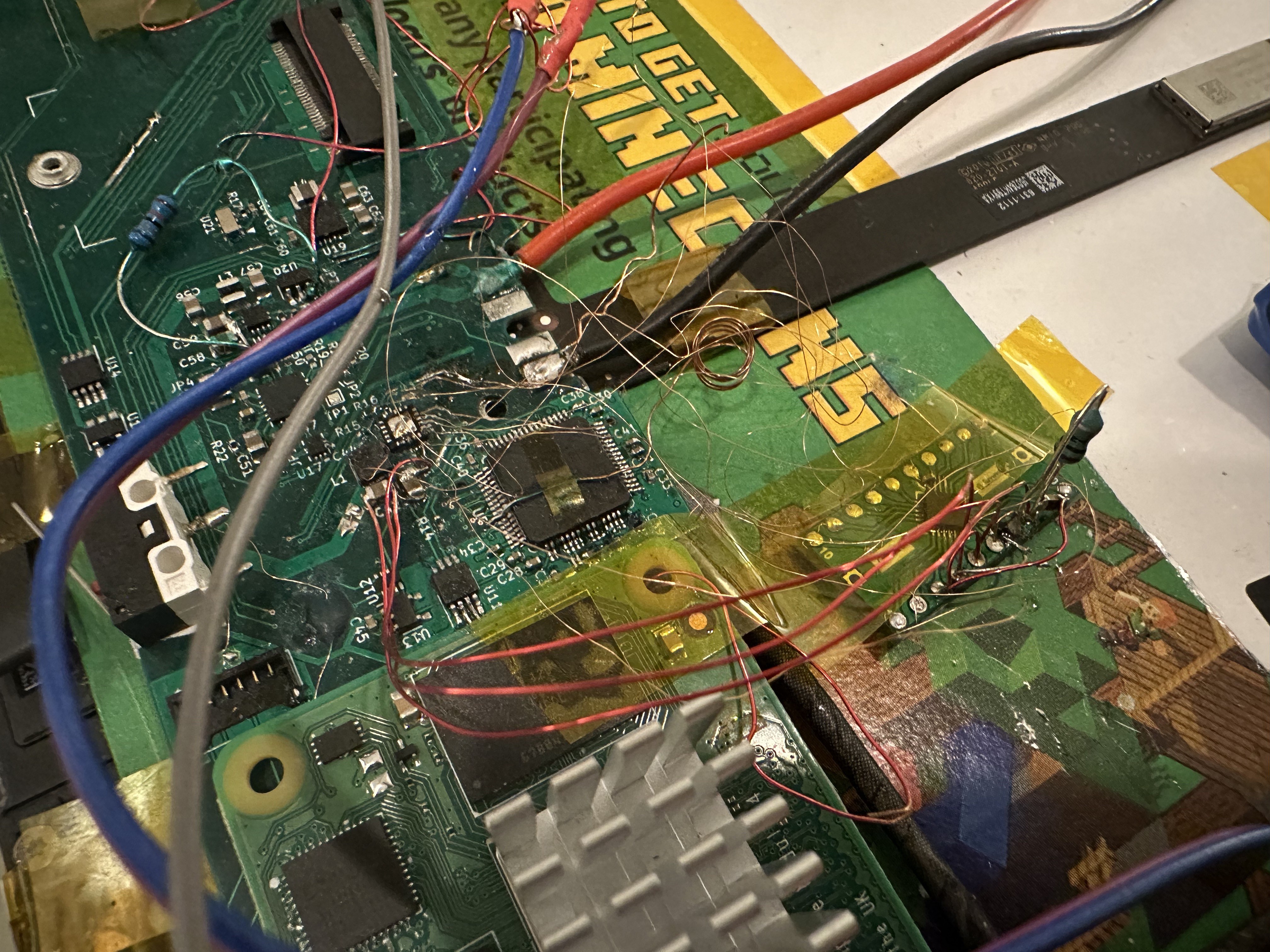
![]()
The mess of wires here is mostly bodge connections from that QFN breakout to traces on the PCB -- battery power, i2c, PWM and enable pins, and the anode + cathode pins for the LCD backlight. This works, but has some issues: the backlight flickers a lot when the Pi is under load (or using wifi or something?) I think the backlight controller is hitting its under-voltage lockout. At first, I had left the large decoupling cap on the main PCB, but in this configuration the backlight would strobe for about a second on boot, then would shut off. Moving the capacitor to the breakout board helped, but the flicker remains. I may add more capacitance.
I also think one of the LED strings isn't connected correctly, causing the "stagelight" appearance at the top of the screen.
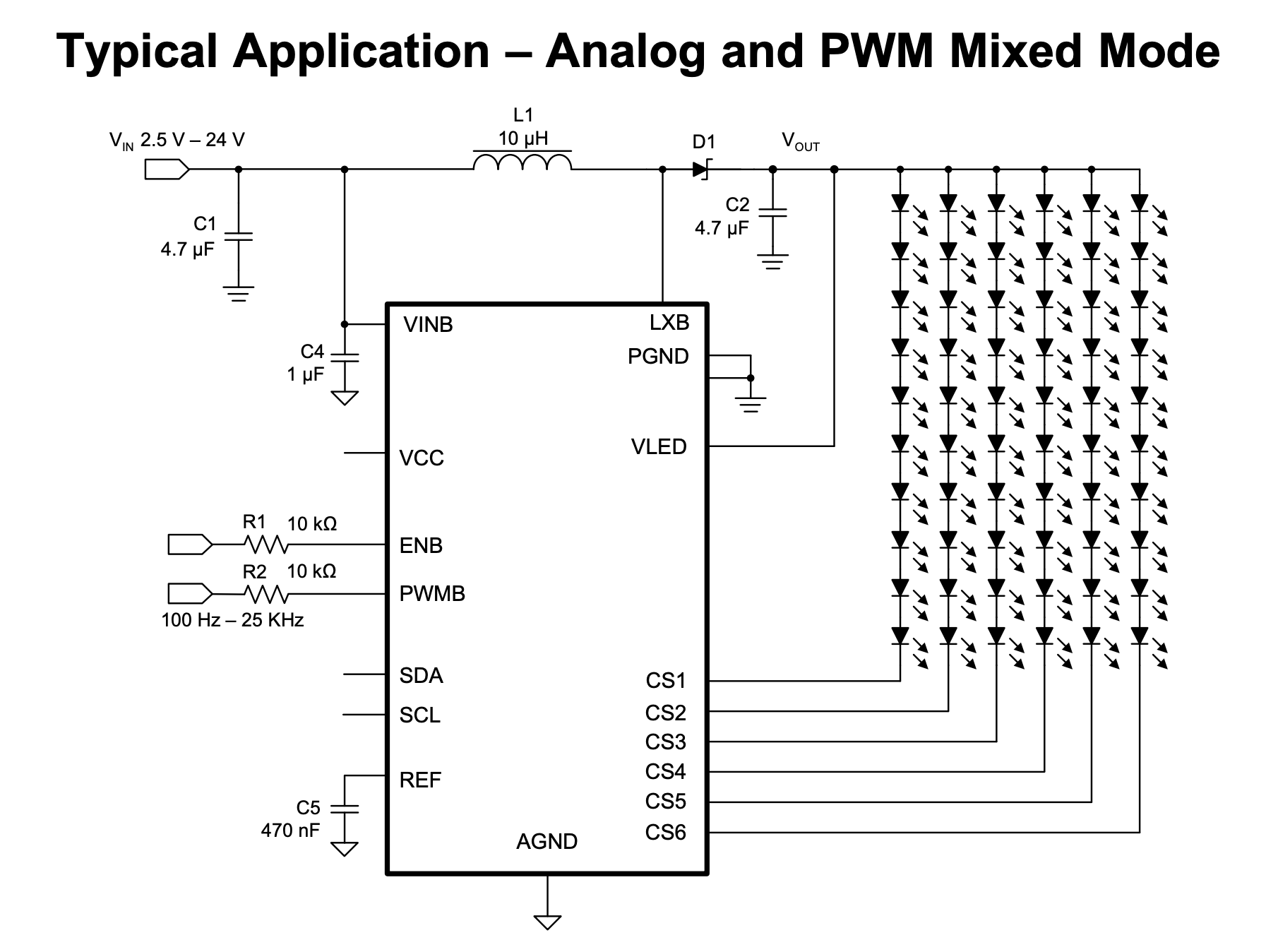
(The backlight in the iPad, like many other LCDs, is 6 strings of LEDs:
![]()
Example schematic from the datasheet for the TPS61177A, the backlight controller I'm using. This keeps the voltage at something reasonable -- about 20V in the iPad -- and also means that a single LED failure doesn't cause the whole backlight to go out.)
The video
The touchscreen doesn't work quite right - it's detecting phantom touches. I've decreased the sensitivity, which helps slightly, but also makes it miss some real touches. This makes it pretty frustrating to use. (In the video, you can see me struggle to shut down the Pi using the shutdown menu while the touchscreen keeps trying to read MagPi.) The GT9110 chip I'm using has terrible publicly-available documentation, so tuning its configuration will be lots of trial and error.
Even with all these problems, it's really beginning to feel like a tablet.
-
The LCD works!
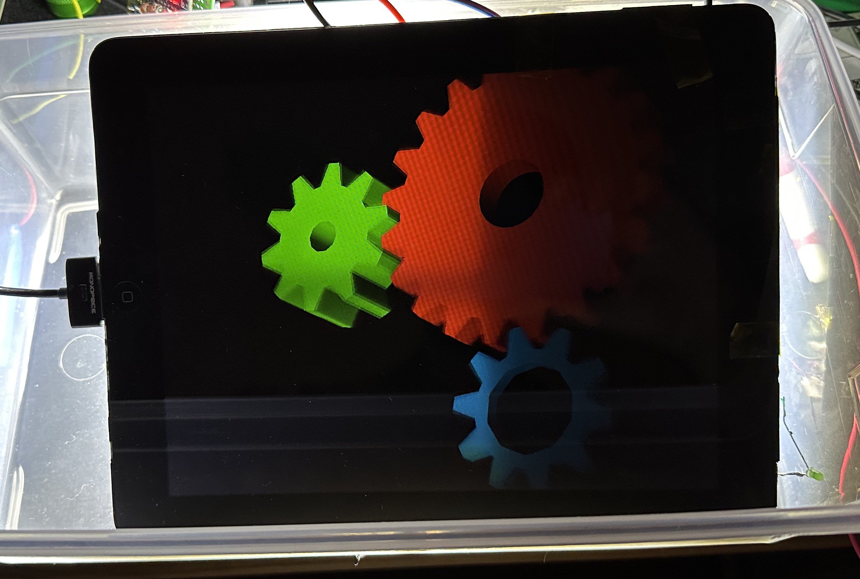
10/07/2022 at 07:57 • 0 commentsAfter finding and fixing a few silly mistakes, I finally got the LCD working:
![]()
The iPad's LCD displaying glxgears, backlit by a makeshift backlight — the circuitry for driving the built-in backlight had a mistake that I haven't fixed yet, documented in this project log. The issues I discovered that I had to fix were:
- The registers for HFP, HBP, and Hsync pulse width are 8 bits on the sn65dsi83, but I was trying to set several of these to values above 255. This was causing them to wrap around, meaning my horizontal line frequency was different than I wanted. I had to adjust these values to be <=255.
- I recalled that someone had told me that 4 lanes of DSI doesn't seem to work with the sn65 (at least with the current version of the Linux driver). I had most recently been testing with 4 lanes, so I was getting no LVDS output. Switching to 3 lanes (and adjusting the desired LVDS clock speed downwards so that the DSI clock would be under 500MHz) got the sn65 producing LVDS signals that seemed to work.
- The LVDS connector on the other side of my board had come off. At some point I had tried swapping out the sn65 IC for a fresh one, thinking I might have burned out the LVDS outputs by shorting them to the inconveniently adjacent 1.8V supply pins. During this rework process, the solder on the LVDS connector must have gotten hot enough to melt (it is essentially right behind the sn65).
I'm fortunate that the LCD doesn't seem to mind if I use a different timing configuration than is specified in its datasheet.
Next steps:
- Merge all my various git branches into one branch (the LCD, the touchscreen controller, the RTC, and the sound card)
- Get PCBs made of the bodge board that I've designed which should let me connect the TPS61177A chip onto my board the right way around.
- Try closing up the case.
Once I do those things, this should be a functional tablet! Mostly. There's still the whole software thing to deal with. And I need to figure out how to either use the iPad's original wifi/BT chip or connect the CM4's antenna port to one of the iPad's own antennas. Also I'd like to test the NVMe slot. Oh, and I haven't tested the audio codec+speaker amplifier on this revision of the board, I think.
But still! Tangible progress!
-
Some progress on the LCD
07/22/2022 at 06:31 • 0 commentsThe iPad's LCD wants its video input data in the LVDS format, but the CM4 can't output LVDS. It can, however, output DSI video, and there are chips like the sn65dsi83-q1 from TI which can convert from DSI to LVDS.
About a year ago, I had gotten the sn65dsi83 somewhat working on the previous revision of my board. However, I ran into an issue with that board design that was difficult to work around: That board was designed to work as a hat for a full-size Pi (for ease of controlling which parts of the board were connected), so it only supported the 2 lanes of DSI that are exposed on the 15-pin display FFC on the Pi 4. This made it impossible to get clock speeds in the right ranges to make everything happy:
The LCD panel from the iPad wants an LVDS clock between 97MHz and 103MHz. The sn65dsi83 driver calculates a DSI clock speed for for a desired LVDS clock frequency based on the pixel rates required and how many lanes of DSI you're using. (In this case, it wanted a 600MHz clock, which the sn65 would then divide by 6 to get 100MHz.) The Pi's DSI driver, vc4_dsi, then rounds this requested DSI clock speed up to the nearest integer division of 1.5GHz. In the case of 2 DSI lanes, this meant the Pi was trying to send a 750MHz DSI clock, and divide by 6 to get a 125MHz LVDS clock. These clock speeds are out of spec for both the sn65 (which only supports up to 500MHz DSI clocks) and the panel (which wants 100MHz clocks).
The fix would be to use 4 lanes of DSI -- with 4 lanes, the sn65dsi83 driver would request a 300MHz clock (which the vc4_dsi driver would happily provide, as that's one fifth of 1500 MHz), which the sn65 would then divide by 3 to get the 100MHz LVDS clock. I set aside any further work on the sn65 until I had my second board revision.
Picking up where I left off
Now that I've got my CM4-based board (which has all 4 lanes of DSI routed), it was time to try getting video working again.
One of the first things I did was to skim through the updates on this massive thread on the Raspberry Pi forums, which is the de facto place to discuss using the sn65dsi83 with the Raspberry Pi. So, so many updates.
An engineer from the Raspberry Pi foundation, who goes by 6by9 on the forums, maintains a branch of the Linux kernel with patches to the sn65dsi83 driver. I pulled the latest version of their branch and merged it with the changes from my branch from last year. I double-checked the settings in the device tree overlay file (updating e.g. which GPIO pins are connected to the enable pin on the sn65 and its voltage regulator).
Before trying it out, I looked at the area of my board near the sn65 to check for short circuits and such. (This is my last copy of the chip, and they're only available from a few places, which are selling at quite a bit above MSRP.)
Satisfied that I wasn't going to fry the chip, I enabled the dtoverlay. I was greeted with this error message on boot:
[ 18.154108] sn65dsi83 10-002d: failed to attach dsi to host: -517
I used some tricks I've learned during this project to get more information out of the kernel at boot: specifically, adding a bunch of dyndbg flags to the kernel command line in /boot/cmdline.txt:
ti_sn65dsi83.dyndbg="+pmf" vc4.dyndbg="+pmf" panel_simple.dyndbg="+pmf" drm_kms_helper.dyndbg="+pmf" component.dyndbg="+pmf"
(This enables debug messages in the ti_sn65dsi83, vc4, panel_simple, ... kernel modules.)
After adding some more debug messages to those modules, I ended up with this in my boot log:
[   17.888125] calling  sn65dsi83_driver_init+0x0/0x1000 [ti_sn65dsi83] @ 366
[   17.900948] sn65dsi83 10-002d: supply vcc not found, using dummy regulator
[   17.902829] systemd-journald[136]: Successfully sent stream file descriptor to service manager.
[   17.907747] systemd-journald[136]: Successfully sent stream file descriptor to service manager.
[   17.918315] systemd-journald[136]: Successfully sent stream file descriptor to service manager.
[   17.942603] systemd-journald[136]: Successfully sent stream file descriptor to service manager.
[   17.948459] vc4_dsi fe700000.dsi: vc4_dsi_host_attach called
[   17.948499] component:__component_add: vc4_dsi fe700000.dsi: adding component (ops vc4_dsi_ops [vc4])
[   17.948595] component:try_to_bring_up_master: vc4-drm gpu: trying to bring up master
[   17.948612] component:find_components: vc4-drm gpu: Looking for component 0
[   17.948629] component:find_components: vc4-drm gpu: Looking for component 1
[   17.948645] component:find_components: vc4-drm gpu: Looking for component 2
[   17.948661] component:find_components: vc4-drm gpu: Looking for component 3
[   17.948889] component:find_components: vc4-drm gpu: found component fe700000.dsi, duplicate 0
[   17.948916] component:find_components: vc4-drm gpu: Looking for component 4
[   17.948932] component:find_components: vc4-drm gpu: found component fe004000.txp, duplicate 0
[   17.948948] component:find_components: vc4-drm gpu: Looking for component 5
[   17.948963] component:find_components: vc4-drm gpu: found component fe206000.pixelvalve, duplicate 0
[   17.948978] component:find_components: vc4-drm gpu: Looking for component 6
[   17.948993] component:find_components: vc4-drm gpu: found component fe207000.pixelvalve, duplicate 0
[   17.949008] component:find_components: vc4-drm gpu: Looking for component 7
[   17.949022] component:find_components: vc4-drm gpu: found component fe20a000.pixelvalve, duplicate 0
[   17.949038] component:find_components: vc4-drm gpu: Looking for component 8
[   17.949052] component:find_components: vc4-drm gpu: found component fe216000.pixelvalve, duplicate 0
[   17.949067] component:find_components: vc4-drm gpu: Looking for component 9
[   17.949082] component:find_components: vc4-drm gpu: found component fec12000.pixelvalve, duplicate 0
[   17.949106] component:try_to_bring_up_master: vc4-drm gpu: calling master->ops->bind (ops vc4_drm_ops [vc4])
[   17.953768] component:component_bind: vc4-drm gpu: binding fe400000.hvs (ops vc4_hvs_ops [vc4])
[   17.954158] vc4-drm gpu: bound fe400000.hvs (ops vc4_hvs_ops [vc4])
[   17.954247] component:component_bind: vc4-drm gpu: binding fef00700.hdmi (ops vc4_hdmi_ops [vc4])
[   17.993251] Registered IR keymap rc-cec
[   17.994710] rc rc0: vc4 as /devices/platform/soc/fef00700.hdmi/rc/rc0
[   18.014550] calling  llc_init+0x0/0x1000 [llc] @ 396
[   18.014615] initcall llc_init+0x0/0x1000 [llc] returned 0 after 3 usecs
[   18.056791] input: vc4 as /devices/platform/soc/fef00700.hdmi/rc/rc0/input1
[   18.076250] uart-pl011 fe201000.serial: no DMA platform data
[   18.081757] calling  vlan_proto_init+0x0/0xc4 [8021q] @ 396
[   18.081844] 8021q: 802.1Q VLAN Support v1.8
[   18.081935] initcall vlan_proto_init+0x0/0xc4 [8021q] returned 0 after 90 usecs
[   18.095931] calling  hdmi_codec_driver_init+0x0/0x1000 [snd_soc_hdmi_codec] @ 167
[   18.096558] initcall hdmi_codec_driver_init+0x0/0x1000 [snd_soc_hdmi_codec] returned 0 after 550 usecs
[   18.122330] systemd-journald[136]: Successfully sent stream file descriptor to service manager.
[   18.125745] systemd-journald[136]: Successfully sent stream file descriptor to service manager.
[   18.128567] systemd-journald[136]: Successfully sent stream file descriptor to service manager.
[   18.134728] systemd-journald[136]: Successfully sent stream file descriptor to service manager.
[   18.154051] vc4_dsi fe700000.dsi: vc4_dsi_host_attach got error from component_add
[   18.154088] sn65dsi83 10-002d: devm_mipi_dsi_attach got error from mipi_dsi_attach: -517
[   18.154108] sn65dsi83 10-002d: failed to attach dsi to host: -517
[   18.154812] initcall sn65dsi83_driver_init+0x0/0x1000 [ti_sn65dsi83] returned 0 after 57438 usecs
I notice that the -517 error is happening just after the HDMI audio is initialiing, and recall this message. Double-checking that 517 = EPROBE_DEFER, I apply the workaround from that message. This seems to help -- the driver successfully loads:
[   18.242587] calling  sn65dsi83_driver_init+0x0/0x1000 [ti_sn65dsi83] @ 426
[   18.247840] rtc-pcf85063 1-0051: registered as rtc0
[   18.248975] rtc-pcf85063 1-0051: setting system clock to 2022-07-05T06:55:21 UTC (1657004121)
[   18.251207] initcall pcf85063_driver_init+0x0/0x1000 [rtc_pcf85063] returned 0 after 8361 usecs
[   18.257846] sn65dsi83 10-002d: supply vcc not found, using dummy regulator
[   18.271404] vc4_dsi fe700000.dsi: vc4_dsi_host_attach called
[   18.271443] component:__component_add: vc4_dsi fe700000.dsi: adding component (ops vc4_dsi_ops [vc4])
[   18.271537] component:try_to_bring_up_master: vc4-drm gpu: trying to bring up master
[   18.271553] component:find_components: vc4-drm gpu: Looking for component 0
[   18.271571] component:find_components: vc4-drm gpu: Looking for component 1
[   18.271587] component:find_components: vc4-drm gpu: Looking for component 2
[   18.271601] component:find_components: vc4-drm gpu: Looking for component 3
[   18.271618] component:find_components: vc4-drm gpu: found component fe700000.dsi, duplicate 0
[   18.271635] component:find_components: vc4-drm gpu: Looking for component 4
[   18.271650] component:find_components: vc4-drm gpu: found component fe004000.txp, duplicate 0
[   18.271665] component:find_components: vc4-drm gpu: Looking for component 5
[   18.271680] component:find_components: vc4-drm gpu: found component fe206000.pixelvalve, duplicate 0
[   18.271696] component:find_components: vc4-drm gpu: Looking for component 6
[   18.271711] component:find_components: vc4-drm gpu: found component fe207000.pixelvalve, duplicate 0
[   18.271726] component:find_components: vc4-drm gpu: Looking for component 7
[   18.271740] component:find_components: vc4-drm gpu: found component fe20a000.pixelvalve, duplicate 0
[   18.271756] component:find_components: vc4-drm gpu: Looking for component 8
[   18.271771] component:find_components: vc4-drm gpu: found component fe216000.pixelvalve, duplicate 0
[   18.271786] component:find_components: vc4-drm gpu: Looking for component 9
[   18.271801] component:find_components: vc4-drm gpu: found component fec12000.pixelvalve, duplicate 0
[   18.271820] component:try_to_bring_up_master: vc4-drm gpu: calling master->ops->bind (ops vc4_drm_ops [vc4])
[   18.273963] component:component_bind: vc4-drm gpu: binding fe400000.hvs (ops vc4_hvs_ops [vc4])
[   18.274341] vc4-drm gpu: bound fe400000.hvs (ops vc4_hvs_ops [vc4])
[   18.274429] component:component_bind: vc4-drm gpu: binding fef00700.hdmi (ops vc4_hdmi_ops [vc4])
[   18.279785] Registered IR keymap rc-cec
[   18.280394] rc rc0: vc4 as /devices/platform/soc/fef00700.hdmi/rc/rc0
[   18.281000] input: vc4 as /devices/platform/soc/fef00700.hdmi/rc/rc0/input1
[   18.282706] vc4_hdmi fef00700.hdmi: 'dmas' DT property is missing or empty, no HDMI audio
[   18.282773] vc4-drm gpu: bound fef00700.hdmi (ops vc4_hdmi_ops [vc4])
[   18.282933] component:component_bind: vc4-drm gpu: binding fef05700.hdmi (ops vc4_hdmi_ops [vc4])
[   18.300472] Registered IR keymap rc-cec
[   18.301060] rc rc1: vc4 as /devices/platform/soc/fef05700.hdmi/rc/rc1
[   18.301764] input: vc4 as /devices/platform/soc/fef05700.hdmi/rc/rc1/input2
[   18.306737] vc4_hdmi fef05700.hdmi: 'dmas' DT property is missing or empty, no HDMI audio
[   18.306924] vc4-drm gpu: bound fef05700.hdmi (ops vc4_hdmi_ops [vc4])
[   18.307033] component:component_bind: vc4-drm gpu: binding fe700000.dsi (ops vc4_dsi_ops [vc4])
[   18.308798] vc4-drm gpu: bound fe700000.dsi (ops vc4_dsi_ops [vc4])
[   18.308905] component:component_bind: vc4-drm gpu: binding fe004000.txp (ops vc4_txp_ops [vc4])
[   18.309281] vc4-drm gpu: bound fe004000.txp (ops vc4_txp_ops [vc4])
[   18.309366] component:component_bind: vc4-drm gpu: binding fe206000.pixelvalve (ops vc4_crtc_ops [vc4])
[   18.309691] vc4-drm gpu: bound fe206000.pixelvalve (ops vc4_crtc_ops [vc4])
[   18.309774] component:component_bind: vc4-drm gpu: binding fe207000.pixelvalve (ops vc4_crtc_ops [vc4])
[   18.310074] vc4-drm gpu: bound fe207000.pixelvalve (ops vc4_crtc_ops [vc4])
[   18.310157] component:component_bind: vc4-drm gpu: binding fe20a000.pixelvalve (ops vc4_crtc_ops [vc4])
[   18.310449] vc4-drm gpu: bound fe20a000.pixelvalve (ops vc4_crtc_ops [vc4])
[   18.310528] component:component_bind: vc4-drm gpu: binding fe216000.pixelvalve (ops vc4_crtc_ops [vc4])
[   18.310772] vc4-drm gpu: bound fe216000.pixelvalve (ops vc4_crtc_ops [vc4])
[   18.312594] component:component_bind: vc4-drm gpu: binding fec12000.pixelvalve (ops vc4_crtc_ops [vc4])
[   18.312989] vc4-drm gpu: bound fec12000.pixelvalve (ops vc4_crtc_ops [vc4])
[   18.330091] [drm] Initialized vc4 0.0.0 20140616 for gpu on minor 1
[   18.340221] brcmfmac: brcmf_cfg80211_set_power_mgmt: power save enabled
[   18.497222] sn65dsi83 10-002d: failed to lock PLL, ret=-110
[   18.516260] Console: switching to colour frame buffer device 128x48
[   18.537765] vc4-drm gpu: [drm] fb0: vc4drmfb frame buffer device
[   18.573145] initcall sn65dsi83_driver_init+0x0/0x1000 [ti_sn65dsi83] returned 0 after 322753 usecs
That line "[ 18.516260] Console: switching to colour frame buffer device 128x48" is encouraging! Ok, how do I test this now?
Searching around, I found https://github.com/richinfante/fbutils, which is a collection of tools for displaying images from the Linux framebuffer. (Graphics without X11 or Wayland!) Unfortunately, nothing seemed to be working - the LCD screen is just black.
Giving up on the framebuffer for a bit, I then installed the Raspberry Pi desktop with sudo apt install raspberrypi-ui-mods
This doesn't seem to help, either -- the LCD is still just black. Then I realize I forgot to plug in the LVDS cable 🤦
I plug in the LVDS cable, and.... still nothing!
Reading over my kernel boot logs again, I notice an error message from the sn65dsi83 driver:
[ 18.497222] sn65dsi83 10-002d: failed to lock PLL, ret=-110
Am I on the right branch?
I remembered that 6by9 actually had three branches relating to the sn65: rpi-5.15.y-dsi, rpi-5.15.y-sn65dsi8x, and rpi-5.15.y-sn65dsi83. The commits on the -sn65dsi8x branch were the most recent, so I had gone with that at first, but figured I should try the other two branches as well.
The -dsi branch was unable to start X -- it would give me this error:
Fatal server error:
(EE) no screens found(EE)
Looking at the boot logs, I noticed this problem:
[ 17.307990] component:try_to_bring_up_master: vc4-drm gpu: master has incomplete components
Moving on to the third branch (rpi-5.15.y-sn65dsi83) is much more successful, and xrandr shows the right resolution:
meatmanek@cm4:~ $ DISPLAY=:0 xrandr
Screen 0: minimum 320 x 200, current 1024 x 768, maximum 7680 x 7680
HDMI-1 disconnected primary (normal left inverted right x axis y axis)
HDMI-2 disconnected (normal left inverted right x axis y axis)
LVDS-1 connected 1024x768+0+0 (normal left inverted right x axis y axis) 0mm x 0mm   1024x768      59.98*+
meatmanek@cm4:~ $ sudo i2cget -f -y 10 0x2d 0xe1
0x00
But why is my screen still black?
Probing one of the DSI signal lines while running xeyes, I could see that there's definitely video signal coming through.
![]()
What I was hoping to see on the screen -- screenshot captured while running the xeyes command. The oscilloscope in this video has its trigger hold-off configured so that each trace the oscilloscope displays is slightly later into the next frame of video, so the effect is that we slowly scan down the image. If you watch carefully, you can notice the eyes' pupils in the signal on the oscilloscope.
And yet, still, no image was showing up on the LCD.
I started reading through the configuration registers on the sn65 to see if anything stood out that could explain why nothing was showing up. Suddenly, the sn65 stopped responding entirely on i2c.
A detour while we fix some basic stuff
Breaking out the trusty logic analyzer, I discovered that the enable pin was being weird - it's just hovering at 1.5V with some weird noise on it, instead of being at the 1.8V that the NTB0102 logic level converter is supposed to drive it to. Also, the 3.3V side is being weird, too -- it's supposed to be 0V or 3.3V, not have weird voltage shifts.
![]()
I wonder if the NTB0102 is improperly soldered or something. After giving it a bit more solder and wicking away the excess, things look better:
![]()
Once I have this fixed, I learn from the sn65's error register that it's not able to lock its PLL to the DSI clock signal. Looking at the DSI clock with my oscilloscope, I see no clock, just a DC offset and a bit of noise.
It took me way longer than I'd like to admit to realize that this was caused by even more bad soldering:
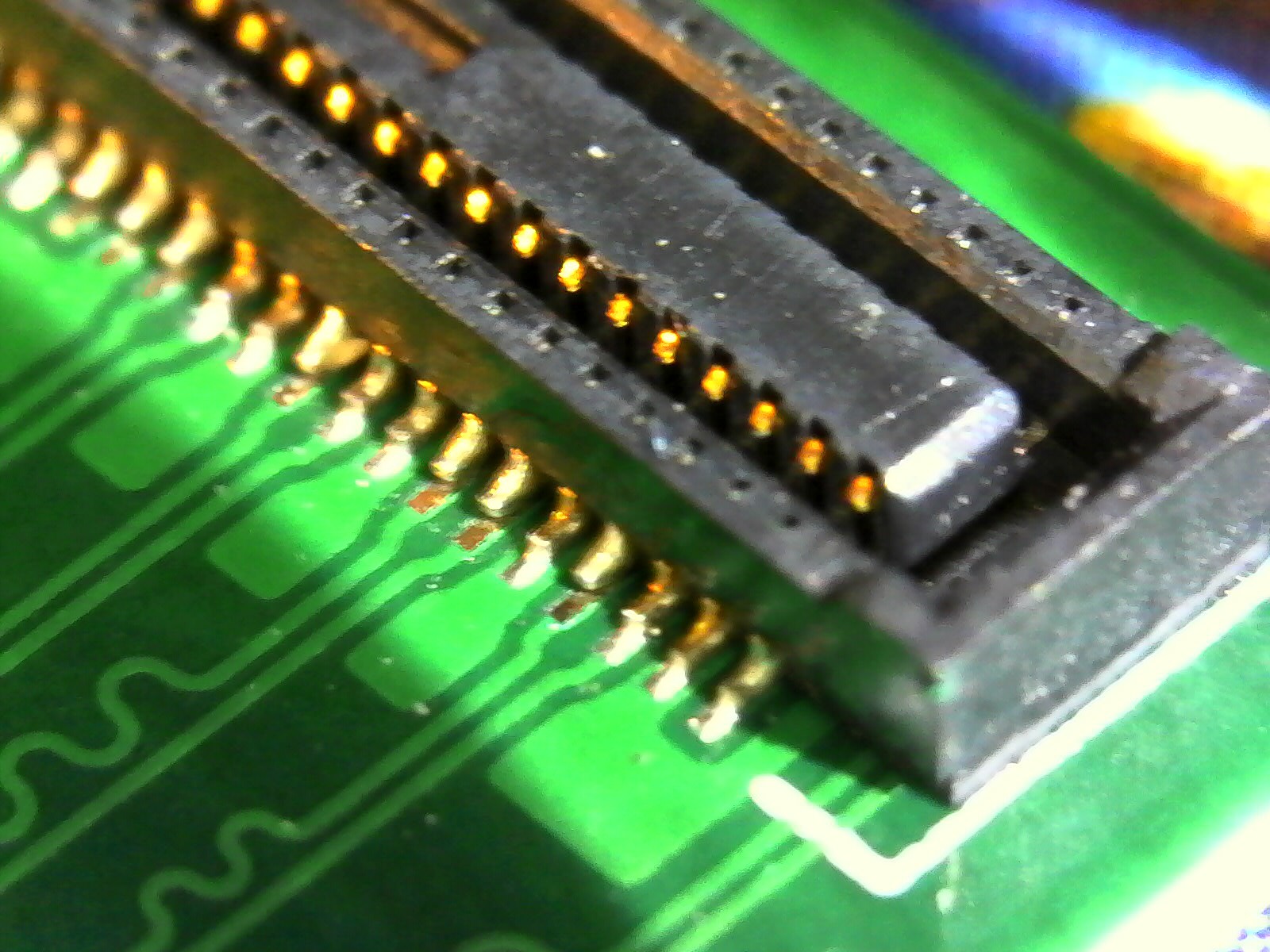
![]()
The DF40HC connector for the CM4, showing 5 of 8 DSI pins without any solder, including the two clock pins. (There are another 2 pins for DSI that aren't pictured here.) With the number of pins disconnected here, it's actually lucky (or unlucky?) that the DSI data lane I chose to probe at first happened to have signal.
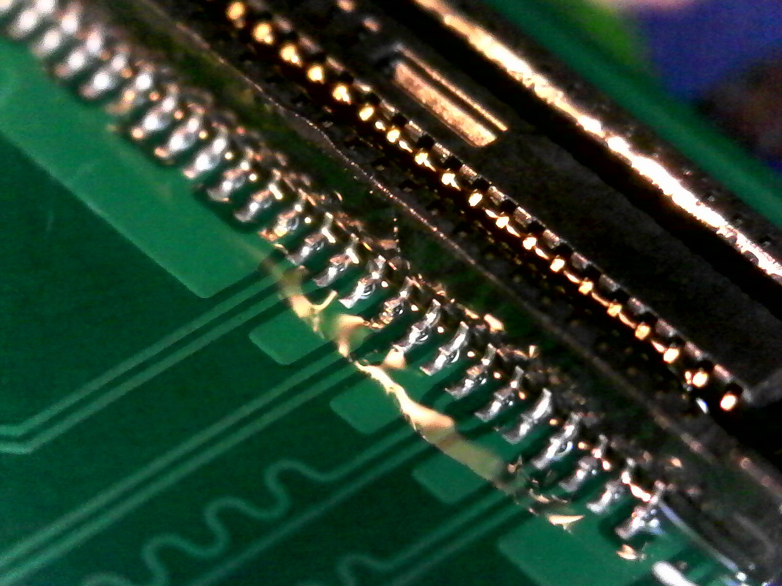
![]()
Better, but not perfect. I subsequently touched up that pin that has less solder than the others. (And cleaned up the flux.) Stuck with no LVDS signal
After fixing the soldering, I'm currently stuck with the following situation:
- The Raspberry Pi seems to be outputting DSI correctly, and I can see signal arriving at all DSI pins of the sn65
- The sn65 doesn't complain about any errors in its error register, including any clock errors.
- The sn65 doesn't output any LVDS signal unless I enable its test pattern.
You had one job, sn65dsi83! Convert my DSI to LVDS!
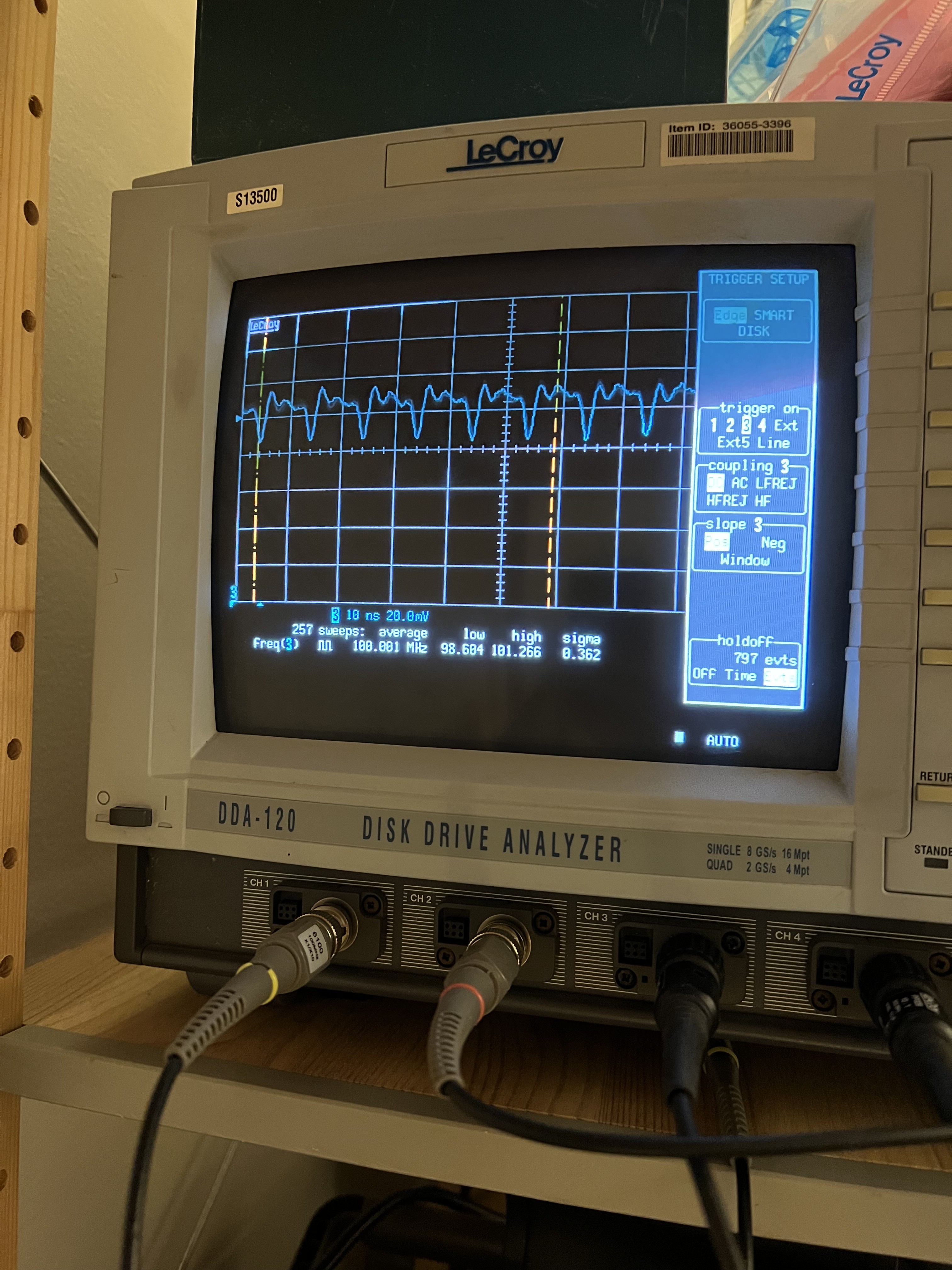
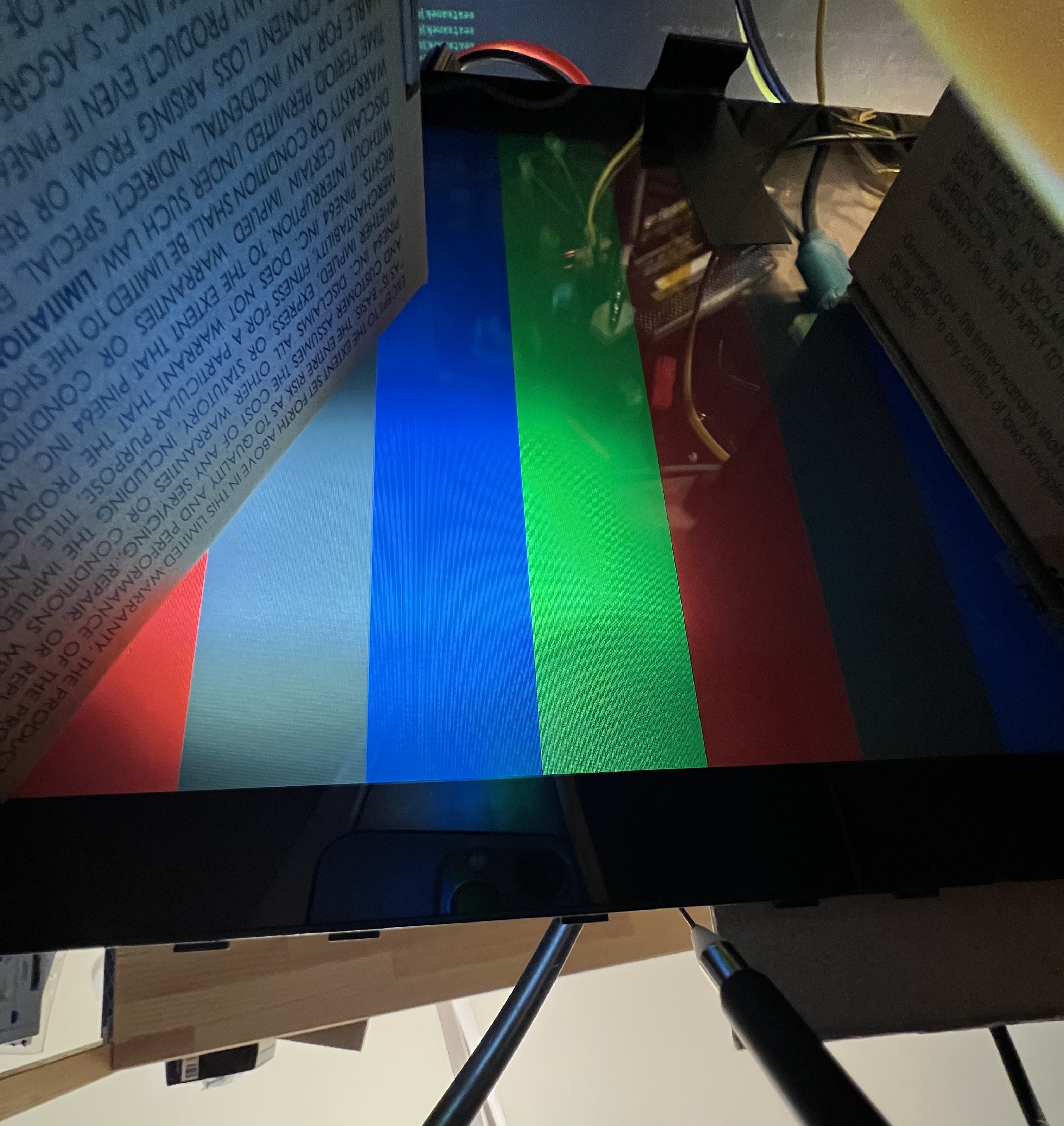
![]()
LVDS data coming from the sn65dsi83 while the test pattern is enabled ![]()
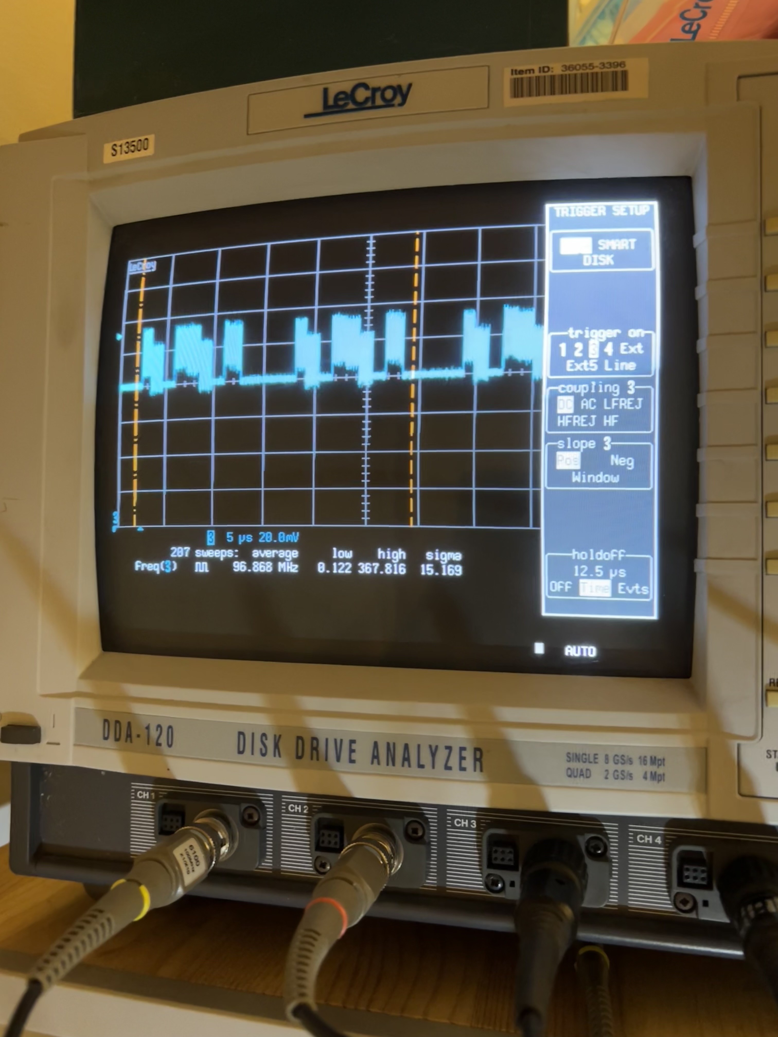
Meaningless LVDS data coming from the sn65dsi83 while it should be outputting the data it receives from DSI. My current best hypothesis is that my problem has to do with the DSI data not having a horizontal blanking interval that is as long as the LVDS data's blanking interval should be: it seems like the Pi is producing a new horizontal line every 13.16 microseconds, while the LVDS signal should produce a new line every 20.84 microseconds.
My "backlight"
I should note that because of the backlight controller issues documented in a previous log entry, my board can't currently drive the backlight built in to the LCD. (I tried hand-soldering the backlight controller chip upside-down but it still doesn't work. I'm planning to make a little bodge PCB that I can solder down, which has pads on the bottom that would connect to my board as well as pads on the top that would connect to the TPS61177 in the right orientation.)
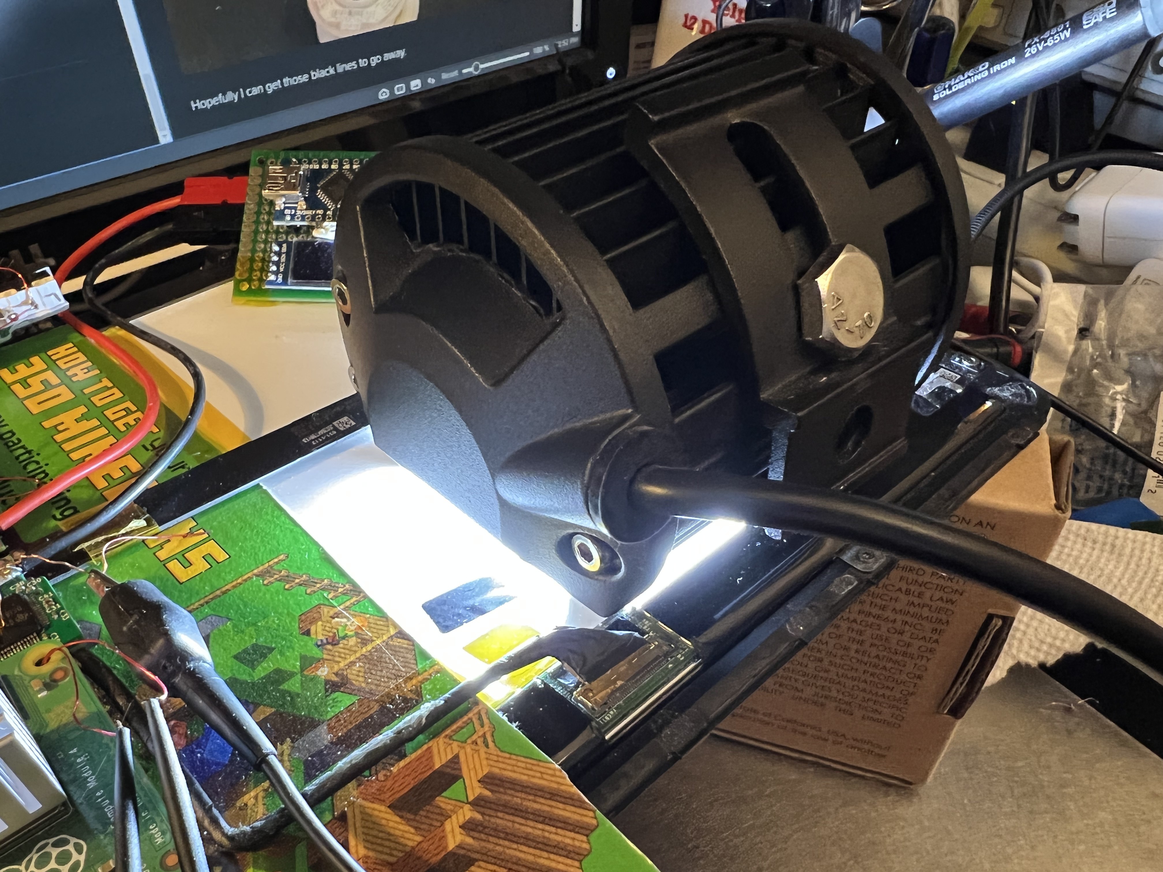
But it turns out, the white reflector used for the backlight isn't 100% opaque, so if you shine enough light in the back, you can see it through the LCD, at least directly underneath where you shine it.
![]()
20 watts of LEDs, standing in for the backlight. ![]()
The sn65dsi83's test pattern, illuminated by my hacky backlight replacement. At this point I've been trying to get video working for about 3 weeks, so I figured I should publish a log entry for what I've been up to, even if it hasn't been successful. Hopefully I'll have a better update soon!
-
Getting the GT9110 touchscreen controller working
07/22/2022 at 06:31 • 0 commentsI've been testing out the GT9110 for the past few days, and finally got it working today.
My board uses a Goodix GT9110 touchscreen controller, which is closely related to a few other parts (GT911, GT928, etc.), and is basically the only touchscreen controller that I could find which met my requirements:
- Has enough drive and sense pins to work with my touchscreen
- A reasonable footprint which doesn't require expensive, high-density PCBs (which excludes the mXT2952, an 0.5mm-pitch BGA)
- Available in small quantities for a reasonable price (which excludes the MXT2912TD-A)
- Actual datasheets are available (which excludes a bunch of Cypress chips)
- Linux drivers are available
(I should note that I haven't found an English datasheet for the GT9110, only one in Chinese. However, I did find English datasheets for related chips, like the GT911 and GT9113. These, plus Google Translate, were enough to lay out my PCB.)
On my previous iteration of the board, the i2c communication to the GT9110 was unreliable -- it wouldn't respond on i2c until a little while after the INT pin went high, which made the Linux goodix driver unhappy. I had guessed that might've been because the bodge I had to do for the INT pin wasn't making a good connection.
Initial progress
I dug up the device tree overlay file I had written for testing, and updated the GPIO numbers to match my new board revision.
Fortunately, the new board doesn't have the same communications issues from the old board -- the Linux driver was able to talk to the GT9110 successfully, and create a file under /dev/input/event*.
Getting stuck
However, beyond initializing the driver, nothing else would happen. The INT pin would go high during driver initialization, and wouldn't change when I touched the screen. No further i2c communication was happening. Looking at the drive pins with an oscilloscope, I could see nothing was happening.
An error immediately stood out to me:
[ 67.112771] Goodix-TS 1-005d: Direct firmware load for goodix_9110_cfg.bin failed with error -2
I searched the web for a goodix_9110_cfg.bin, but couldn't find any example files. I did, however, find a few relevant threads:
- https://forums.raspberrypi.com/viewtopic.php?t=267434
- https://forum.khadas.com/t/connect-goodix-touchscreen-to-vim3/13955
- https://forums.raspberrypi.com/viewtopic.php?t=240001
Nobody seems to mention needing a goodix_9110_cfg.bin (or goodix_911_cfg.bin, goodix_928_cfg.bin, or whatever); everybody managed to get their touchscreens working after a while by fixing basic issues with their device tree overlay files.
Thinking I might have the wrong settings for my interrupt pin, I tried various combinations of pull-up/down/hi-Z, interrupt configuration (IRQ_TYPE_EDGE_FALLING, IRQ_TYPE_EDGE_RISING, IRQ_TYPE_LEVEL_HIGH, IRQ_TYPE_LEVEL_LOW). None of these seemed to help - several of those combinations prevented i2c communications entirely.
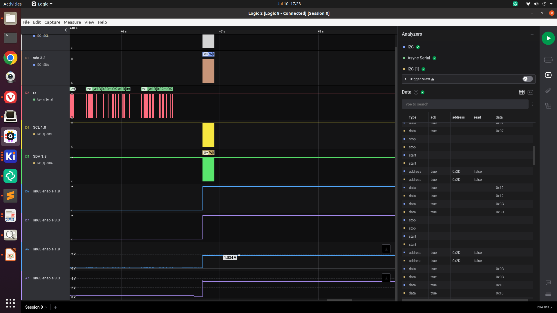
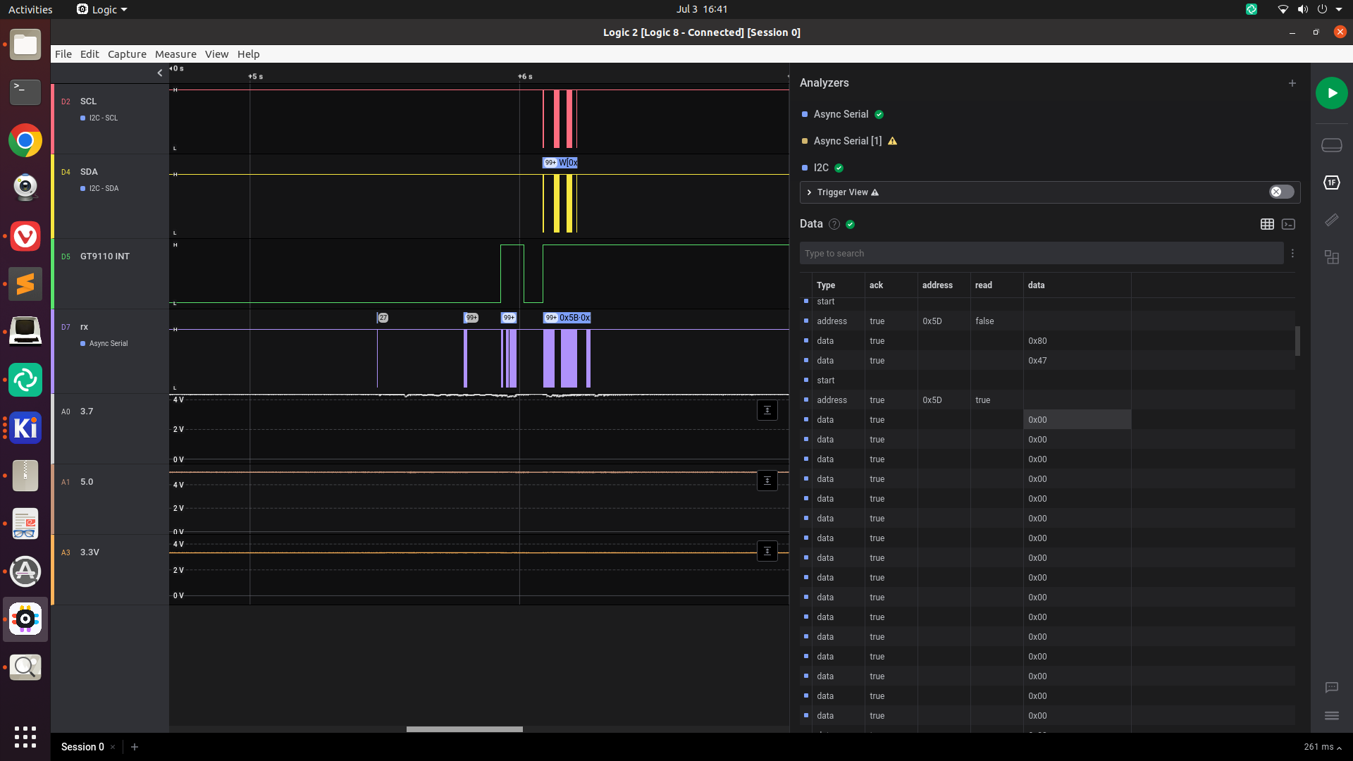
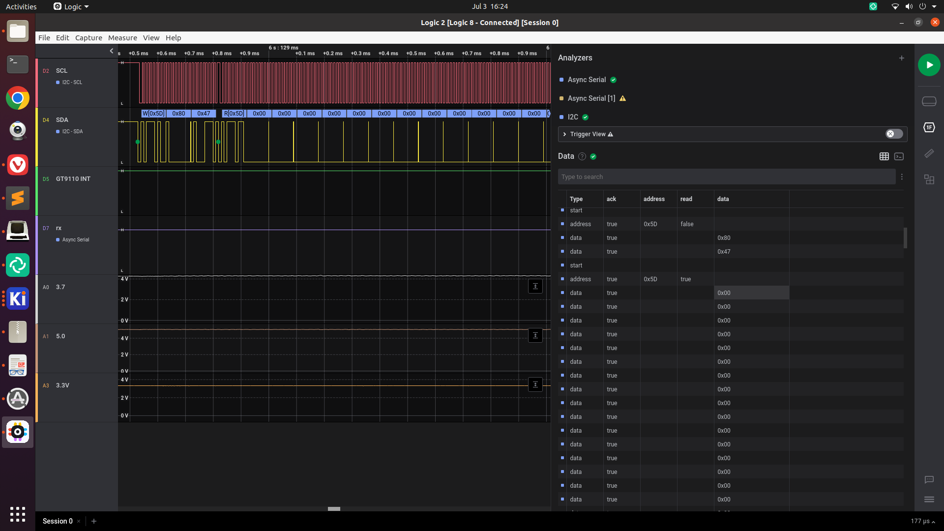
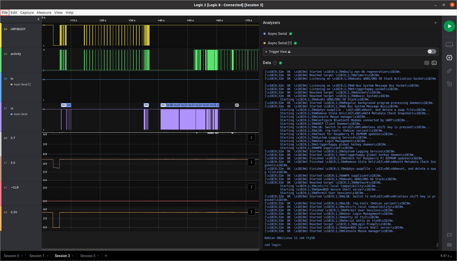
Eventually, I gave up on that and focused on the firmware load error again. Adding a bunch of debug printfs to the driver and watching i2c communication with my logic analyzer (I'm using the Logic 8 from Saleae), I could see that it was:
- Identifying the GT9110 on i2c
- Trying to load the firmware from disk, and complaining that it isn't there. (The internet tells me it's looking in /lib/firmware, among other places)
- Reading a bunch of data from the GT9110 starting at register 0x8047, which is the beginning of the configuration registers.
- Leaving the INT pin high, never signalling that it had data.
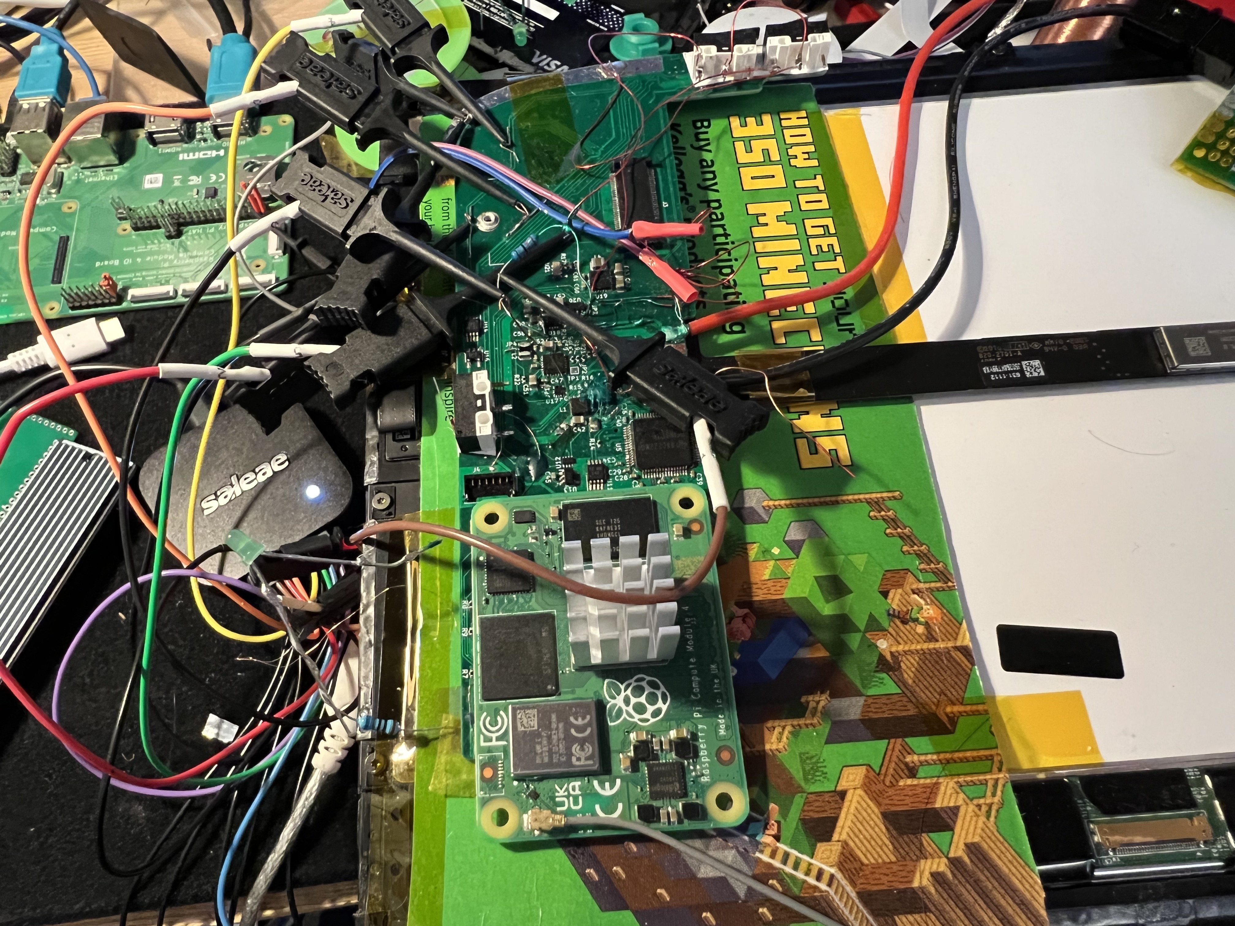
![]()
My board with the logic analyzer hooked up. I neglected to put proper test points on the board, so instead I've just gotten into the habit of scraping some solder mask off with a scalpel and soldering a bit of enameled wire to a trace to give me something to hook a probe to. The bit of cereal box is there to prevent any accidental short-circuits between the back of my board and the metal on the screen. ![]()
Zoomed-out view of driver initialization. The INT pin is left high, which seems to be wrong. It should change state to indicate that the Linux kernel needs to ask the GT9110 for touch location data. ![]()
Zooming in to observe i2c communication. If I'm understanding this correctly, this means all of the configuration registers were set to 0. Unlike a lot of other chips, it seems like the GT9110 has no default values. I probably want to set those to nonzero values.
From my reading of the driver source code, the only way to change the configuration is through a firmware file, so I guess I really need to find or write one.
Breakthrough
I eventually stumbled on this Stack Overflow question, which pointed me to this Arduino library for interfacing with gt9x controllers, where they've defined a constant called g911xFW which is 186 bytes long. This length happens to match the GOODIX_CONFIG_911_LENGTH constant defined in the Linux driver code.
(The Stack Overflow question also had a link to the GT911 Programming Guide, which is handy.)
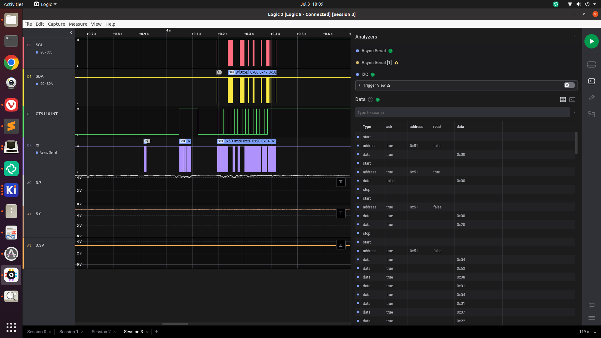
I wrote these bytes to a file, copied it over to my CM4 and put it in /lib/firmware/goodix_9110_cfg.bin, and tried loading my driver again. This time, the i2c and interrupt lines were extremely active:
![]()
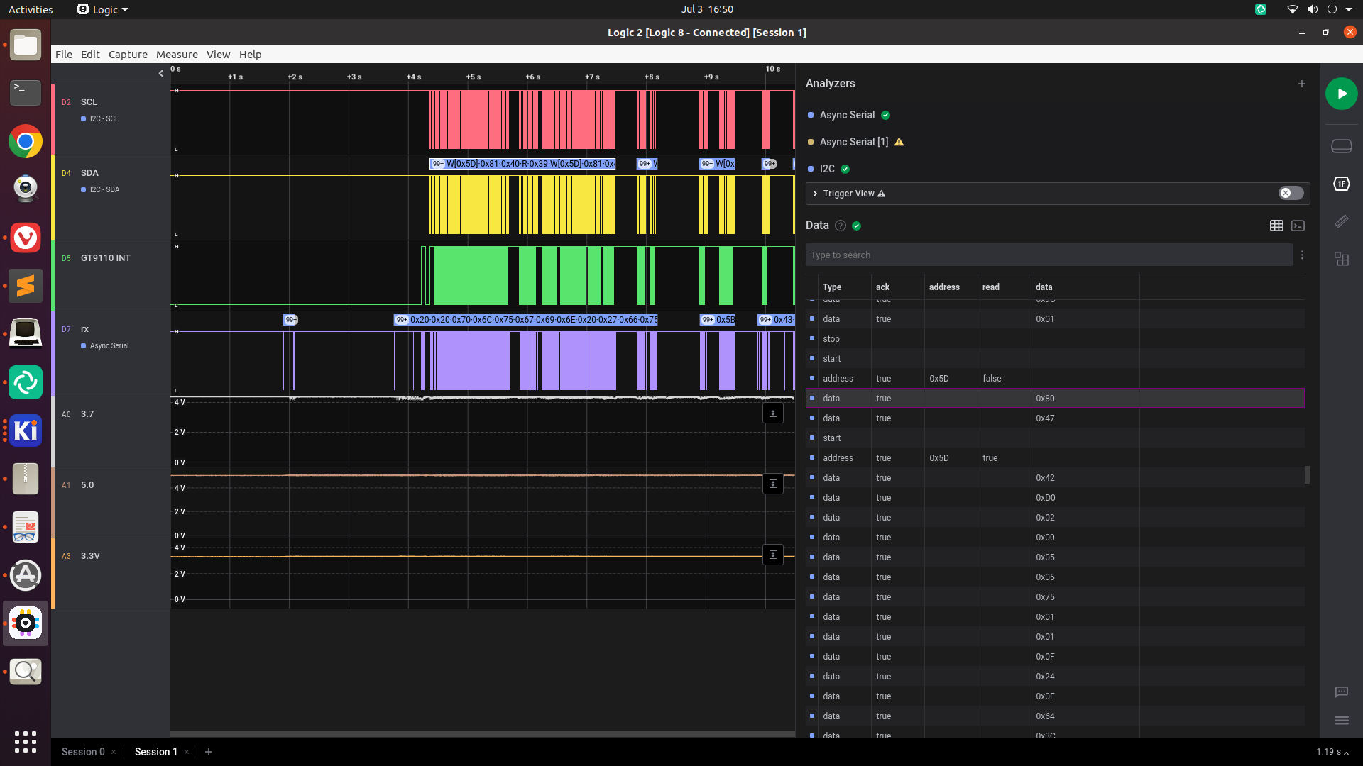
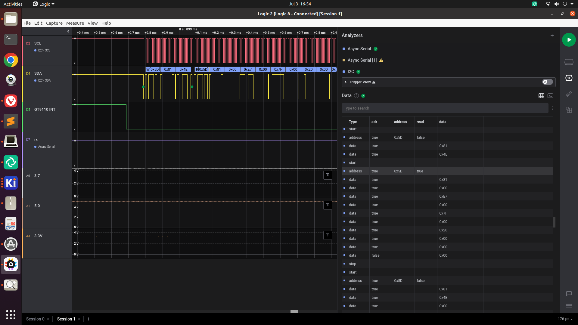
Zooming in, we can tell that immediately after the INT pin goes low, the driver is requesting several registers, starting with 0x814E.
![]()
The goodix driver responding to an interrupt by requesting the touch positions This includes registers 0x8150 through 0x8153, which are the X and Y coordinates of touch 1. This is good! Let's find out if the data is meaningful.
Visualizing the touch data
I wrote a little script to visualize the touch data from /dev/input/eventN using ncurses. Running this with the GT9110 using the configuration we just found, we see that we just get garbage data:
![]()
The GT9110 spitting out random noise, even when I'm not touching it. I ended up reformatting the configuration data into something a little more human-readable, with comments explaining which register each value belongs to. A few things stood out:
- The X and Y dimensions (registers 0x8048 to 0x804b) were set to 720x1280, whereas I need 768x1024
- The Sensor_CH0...Sensor_CH13 registers (0x80b7 to 0x80c4) were set to 0x02, 0x04, ..., 0x1C. Similarly, the Driver_CH0 through Driver_CH24 channels were all set to various numbers between 0x02 and 0x28. I'm surprised these didn't just start at 0x01 and go up from there.
- The registers between Sensor_CH13 and Driver_CH0 (0x80c5 through 0x80d4) were all set to 0x00, as were the registers after Driver_CH24 and before Config_Chksum (0x80ee through 0x80fe). These are all marked as "Reserved" in the GT911 programming guide, but I'm guessing these would be Sensor_CH14 to Sensor_CH29 and Driver_CH25 to Driver_CH41 in the GT9110. (There are exactly the right number of reserved registers here for that to make sense).
I tried taking a stab at modifying the configuration data:
- bumping the very first register, config version (supposedly the GT9110 will refuse to take new configuration if this is less than the current version register)
- changing the resolution
- Setting Sensor_CH0...Sensor_CH29 to 0x01..0x1E
- Setting Driver_CH0..Driver_CH39 to 0x01..0x28 (I don't need to set Driver_CH40 or CH41, since my board only uses 40 drive pins)
I wrote a script that converts my human-readable format to a .bin file by stripping out comments and serializing just the values. It also calculates the checksum according to the algorithm from the Linux driver.
Trying out my modified configuration resulted in the INT-line-stays-high behavior again:
![]()
Hmm.
Eventually, I stumbled on this comment from nik-sharky, the author of that Arduino library, who had posted the configuration of their GT9110-based tablet. Trying this out leads to much better results!
I'm not sure exactly what caused the problem, but this configuration starts Sensor_CH0 at 0x00 instead of 0x01. Maybe setting one of these sensor pins to an invalid value causes the GT9110 to crash or something?
I was able to tweak this file with my script, changing resolution and disabling the 2 unneeded driver channels, and things still work.
![]()
Demonstrating that my GT9110 config works, by moving multiple fingers around on the screen simultaneously. Conclusion
Getting a GT9110 or other GT9x chip working on a custom PCB seems like it's a lot harder than getting it working on an existing board, since you need to come up with a configuration. An existing board would presumably already be configured, so you just need to hook up i2c and the reset/interrupt pins, and get a working device tree entry. (Once you've configured the chip, it seems like it stores the configuration in non-volatile memory so you don't need to reconfigure it again later. This would explain why nobody else needed to mess with goodix_9110_cfg.bin.)
Having a USB logic analyzer / mixed signal device like the Saleae is super handy for debugging embedded problems like this. While it's possible to watch i2c traffic with Linux debugging tools, it's very nice to be able to visually see the state of the interrupt pin and the i2c communication. Having the ability to copy-paste is super nice, too -- something that would be difficult with a standalone oscilloscope.
-
Real-time clock: It's nice when something is easy.
07/22/2022 at 06:30 • 0 commentsAt the very last minute before ordering my PCBs, I realized I probably wanted a real-time clock on the board somewhere. I searched on Digi-Key, found the RV-8263-C7, which was:
- in stock (not anymore, lol)
- cheap
- tiny
- requires minimal external components (just a decoupling cap and a pull-up resistor on an output enable pin)
- has a Linux kernel driver (this chip has the same protocol as the PCF85063)
I found an empty spot on my board with I2C and VBAT lines nearby, and laid it out in a few minutes.
Tonight, I decided to see if it was working:
Throw together a quick dtoverlay file:
/dts-v1/;
/plugin/;

/ {
    compatible = "brcm,bcm2835";

    fragment@0 {
        target = <&i2c1>;
        __overlay__ {
            #address-cells = <1>;
            #size-cells = <0>;
            status = "okay";


            rv8263: rtc@51 {
                compatible = "microcrystal,rv8263";
                reg = <0x51>;
                // quartz-load-femtofarads = <12500>;
            };
        };
    };
};
(This is basically just device tree overlay boilerplate plus the example from the documentation.)
Compile with make -j4 ARCH=arm64 CROSS_COMPILE=aarch64-linux-gnu- dtbs, copy the output dtbo file to the CM4's /boot/overlays directory, and run dtoverlay pipad-rtc.dtbo to load the overlay. Test with sudo hwclock --systohc then sudo hwclock --get. Add dtoverlay=pipad-rtc to /boot/config.txt, reboot, check sudo hwclock --get again, and it's still working.
Remove the fake-hwclock package and disable the systemd unit with the instructions on https://pimylifeup.com/raspberry-pi-rtc/, and double-check that it's actually reading the hardware clock on startup (and not just using NTP) by using rfkill block wifi to turn off wifi, reboot, and check that the time is accurate.
No incorrect PCB footprints or unwired pins, no Linux kernel debugging. Just things working correctly on the first try. Feels good.
-
Figuring out why the CM4 wouldn't boot when attached to my board
07/22/2022 at 06:29 • 0 commentsIn my previous log entry, I had fried my CM4 by shorting 5V to 3.3V, so I had to order a replacement, which arrived last week.
The next thing for me to test is whether I can boot the CM4 on my board, so I installed Raspberry Pi OS and set enable_uart=1 in /boot/config.txt. With the CM4 still in the CM4IO, I verified that I could see boot messages and log into the CM4 over serial.
I bodged some wires onto the UART traces on my board and connected them to my USB-serial adapter. I moved the CM4 off the CM4IO and onto my own board, and booted it, and.... nothing. Zero output from the UART.
I figured it must be crashing somewhere during the bootloader or early kernel boot settings, so I moved the CM4 back to the CM4IO and:
- added console=ttyS0,115200n8 loglevel=7 earlycon=uart8250,mmio32,0xfe215040 to my /boot/cmdline.txt, to get early kernel messages.
- set BOOT_UART=1 in boot.conf to get output from the bootloader.
Still nothing...
After a while, I figured out that the TX pin on my 100-pin connector wasn't properly soldered to my board. Of all the pins to have issues, it had to be that pin!
At this point, it still isn't booting, but I can at least see kernel messages. I would get a warning at some point during boot:
[    3.178888] ------------[ cut here ]------------
[    3.183639] Firmware transaction timeout
[    3.183693] WARNING: CPU: 2 PID: 1 at drivers/firmware/raspberrypi.c:67 rpi_firmware_property_list+0x1dc/0x250
[    3.197794] Modules linked in:
[    3.200888] CPU: 2 PID: 1 Comm: swapper/0 Not tainted 5.15.32-v8+ #1538
[    3.207583] Hardware name: Raspberry Pi Compute Module 4 Rev 1.1 (DT)
[    3.214098] pstate: 80000005 (Nzcv daif -PAN -UAO -TCO -DIT -SSBS BTYPE=--)
[    3.221144] pc : rpi_firmware_property_list+0x1dc/0x250
[    3.226432] lr : rpi_firmware_property_list+0x1dc/0x250
[    3.231719] sp : ffffffc00960b9b0
[    3.235068] x29: ffffffc00960b9b0 x28: 0000000000000000 x27: 0000000000000004
[    3.242300] x26: ffffffc009a5d008 x25: ffffff8002aa8b80 x24: 0000000000001000
[    3.249530] x23: 0000000000000014 x22: ffffffc008e8a9c8 x21: ffffff80020b7200
[    3.256758] x20: ffffffc009a5d000 x19: ffffffc009491158 x18: 0000000000000010
[    3.263986] x17: 0000000000000001 x16: 0000000000000019 x15: 0720072007200720
[    3.271214] x14: 0720072d072d072d x13: 74756f656d697420 x12: ffffffc0093a6670
[    3.278442] x11: 0000000000000003 x10: ffffffc00938e630 x9 : ffffffc0080ec768
[    3.285670] x8 : 0000000000017fe8 x7 : c0000000ffffefff x6 : 0000000000000001
[    3.292899] x5 : 0000000000057fa8 x4 : 0000000000000000 x3 : 0000000000000001
[    3.300126] x2 : 0000000000000000 x1 : 529515f3f0203b00 x0 : 0000000000000000
[    3.307354] Call trace:
[    3.309824]  rpi_firmware_property_list+0x1dc/0x250
[    3.314760]  rpi_firmware_property+0x78/0x110
[    3.319169]  rpi_domain_on+0x6c/0x90
[    3.322789]  genpd_power_on.part.23+0x188/0x220
[    3.327375]  __genpd_dev_pm_attach+0x104/0x238
[    3.331870]  genpd_dev_pm_attach+0x6c/0x88
[    3.336014]  dev_pm_domain_attach+0x28/0x40
[    3.340249]  platform_probe+0x58/0xe0
[    3.343957]  really_probe+0xc0/0x318
[    3.347573]  __driver_probe_device+0x80/0xe8
[    3.351892]  driver_probe_device+0x88/0x118
[    3.356123]  __driver_attach+0x78/0x110
[    3.360004]  bus_for_each_dev+0x7c/0xd0
[    3.363890]  driver_attach+0x2c/0x38
[    3.367505]  bus_add_driver+0x194/0x1f8
[    3.371385]  driver_register+0x6c/0x128
[    3.375265]  __platform_driver_register+0x30/0x40
[    3.380026]  xhci_plat_init+0x38/0x44
[    3.383737]  do_one_initcall+0x54/0x2a0
[    3.387619]  kernel_init_freeable+0x250/0x2d8
[    3.392031]  kernel_init+0x2c/0x130
[    3.395564]  ret_from_fork+0x10/0x20
[    3.399186] ---[ end trace b159b7c67bd50e8b ]---
Then after a few more messages, it would hang.
From what I can tell from this issue where people saw the same "Firmware transaction timeout" warning, this happens when the code running on the VC4 locks up.
Getting more output
The internet told me to add initcall_debug to my kernel command line to get more output on startup. This prints a message per kernel subsystem on boot.
I could tell from this that the Firmware transaction timeout was happening within xhci_plat_init.
[    7.367700] calling  xhci_plat_init+0x0/0x44 @ 1
[    8.405222] ------------[ cut here ]------------
[    8.409920] Firmware transaction timeout, chan 8 data def00000
...
[    8.632151] initcall xhci_plat_init+0x0/0x44 returned 0 after 1230233 usecs
(XHCI has to do with USB, but nothing made sense yet. USB seems to be working -- I am able to use usbboot to mount the CM4's eMMC storage on another computer.)
I could also see that the boot was hanging in gpio_led_driver_init, because I saw this message:
[ 17.890149] calling gpio_led_driver_init+0x0/0x30 @ 1
with no corresponding line telling us that it had finished, e.g.:
initcall gpio_led_driver_init+0x0/0x30 returned X after Y usecs
Even more output
I spent a bit of time staring at RPi-related kernel code: the rpi_firmware_transaction function (where the timeout is happening) seems to use an "mbox" to communicate with the Pi's firmware. mbox is some generic code in the kernel, but each platform has its own implementation. The CM4's mbox is implemented in bcm2835-mailbox.c.
I noticed that bcm-2835-mailbox.c has a few dev_dbg() calls, which would print debug messages. To get these to print, you need to use the kernel's dynamic debug functionality: Per this stackoverflow answer, the kernel needs to be compiled with CONFIG_DYNAMIC_DEBUG=y. Then, you can add something like dyndbg="file bcm2835-mailbox.c +p" to your kernel command line. This will enable all dev_dbg() calls in that file.
Doing that, I saw this pattern of Request 0xDED00008 followed by Reply 0xDED00008:
[    6.626527] [1] bcm2835_mailbox:bcm2835_send_data:90: bcm2835-mbox fe00b880.mailbox: Request 0xDEF00008
[    6.626537]  bcm2835_mailbox:bcm2835_mbox_irq:77: bcm2835-mbox fe00b880.mailbox: Reply 0xDEF00008
This stops around the time of that Firmware transaction timeout message:
[ 7.372996] [1] bcm2835_mailbox:bcm2835_send_data:90: bcm2835-mbox fe00b880.mailbox: Request 0xDEF00008
[ 8.405222] ------------[ cut here ]------------
[ 8.409920] Firmware transaction timeout, chan 8 data def00000
From this point on, all Requests have no corresponding Reply.
This seems to confirm that the firmware was locking up during the xhci_plat_init call (as opposed to locking up prior to that call, and xhci_plat_init is just the first thing to notice)
Success!
I remembered that there's an entry in config.txt regarding USB behavior:
...
[cm4]
# Enable host mode on the 2711 built-in XHCI USB controller.
# This line should be removed if the legacy DWC2 controller is required
# (e.g. for USB device mode) or if USB support is not required.
otg_mode=1

...
After commenting out the otg_mode line, my CM4 actually boots while attached to my board!
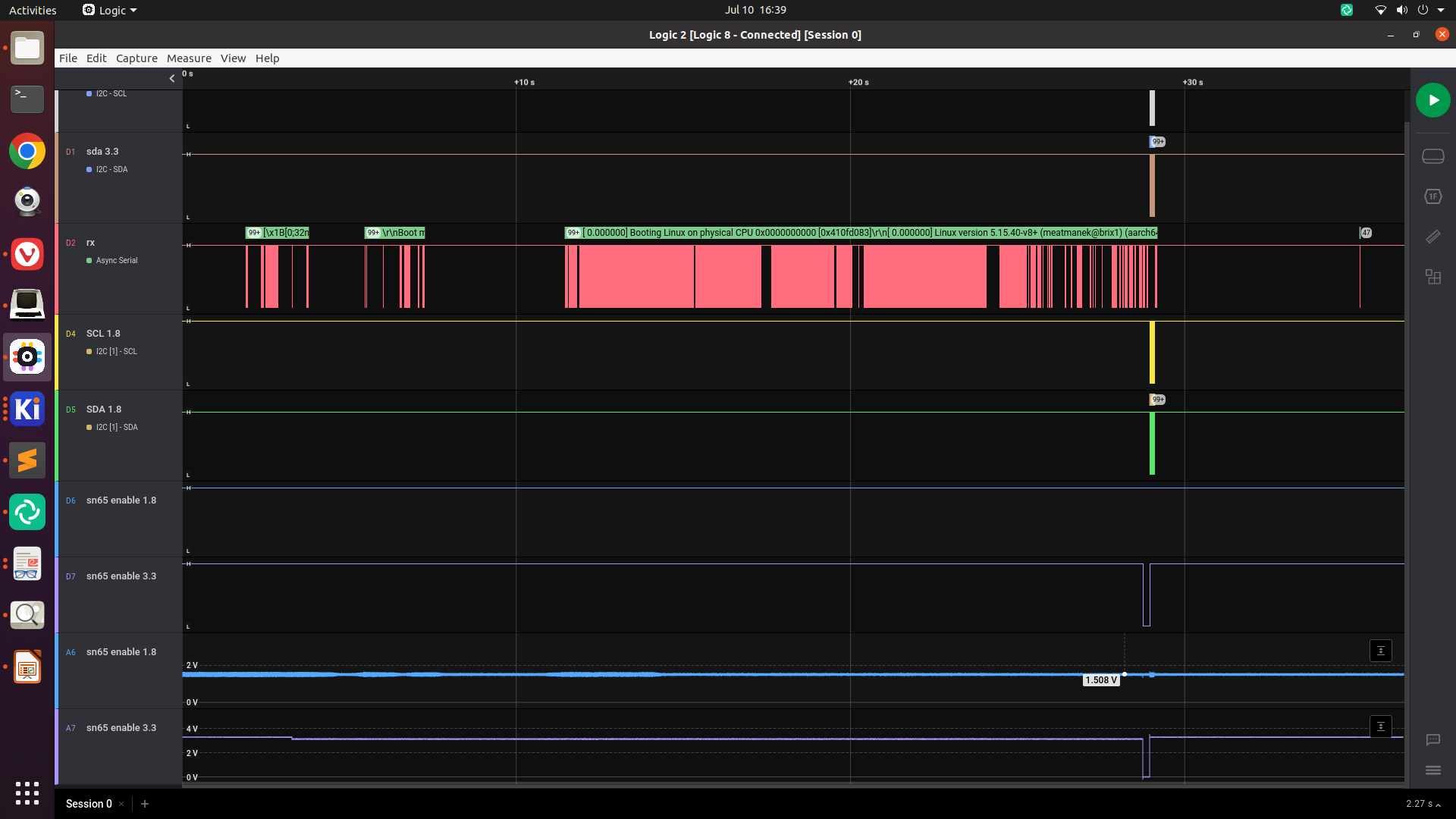
![]()
Logic analyzer showing a login prompt on the serial output Next step: figure out why wifi isn't working, so that I can use SSH instead of serial.
-
CM4 carrier board: chip shortage pain, bodges, silly mistakes, and tragedy.
07/22/2022 at 06:29 • 0 commentsChip shortage problems
Shortly after my last project log, I tried to place an order for all the new components that I'd need for the next revision of my board, as well as re-stocking anything that I had already used most of. I discovered that my backlight controller of choice had gone out of stock with indefinite lead times, so I had to swap to a different backlight driver. (I switched from the TPS61176 to the TPS61177, which was the next cheapest suitable controller on DigiKey.)
I ordered my parts then modified my PCB design to accommodate the new chip.
Fit Testing
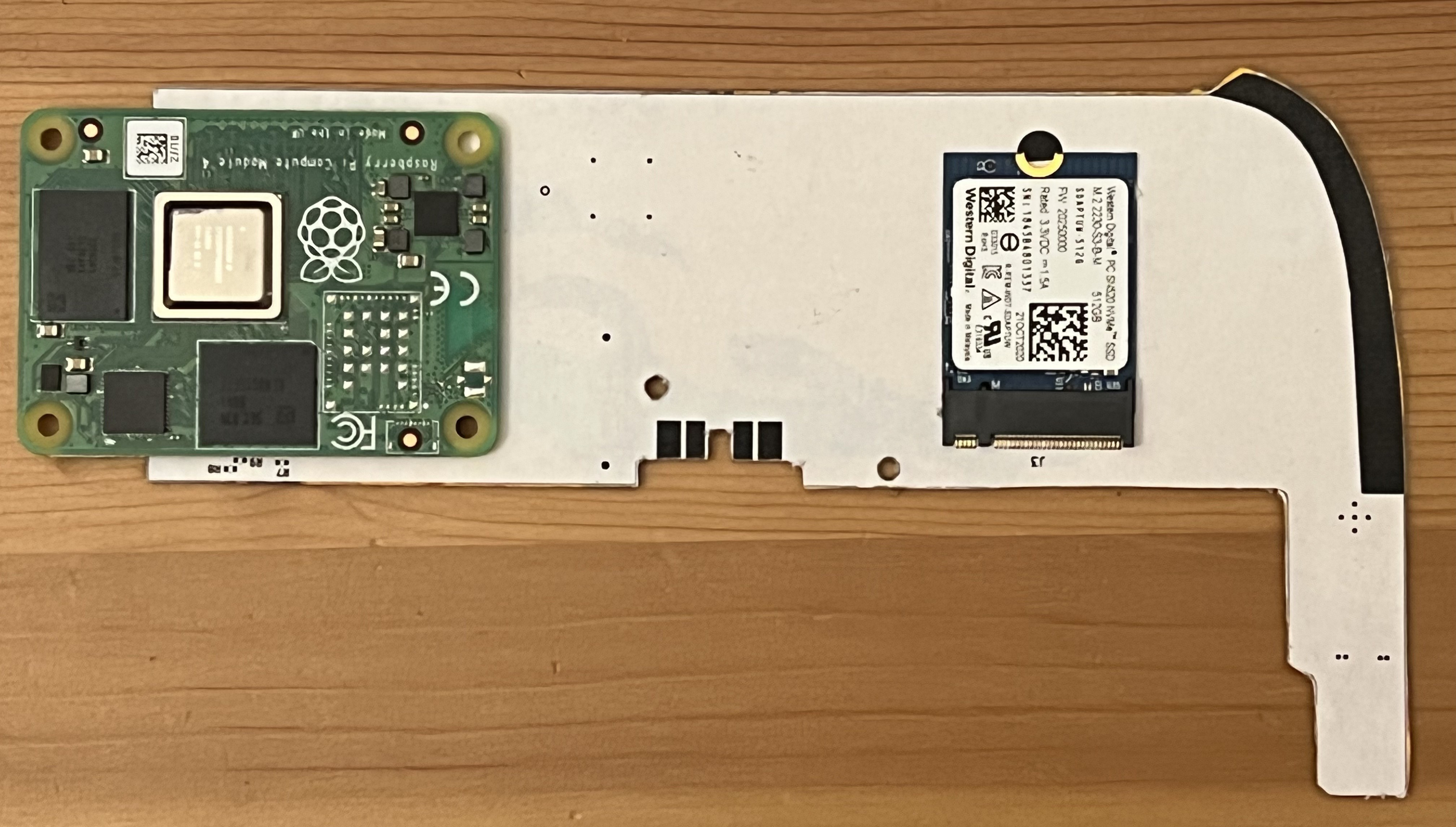
![]()
Once I had parts in hand, I made a mockup of my board by printing the front and back solder mask layers on separate sheets of paper, and then gluing them to either side of a piece of cardboard taken from a soda can box. (This stackup comes remarkably close to the 0.8mm thickness of my PCB.) With some double-sided tape, I affixed the connectors for the largest components -- the CM4 and the NVMe SSD -- snapped the CM4 and SSD in place, and did a fit test in my iPad case. The screen did not want to drop into place.
I found a few things that I could change to improve the fit:
- I rotated the CM4 180 degrees, so that the BCM2711 processor (the thickest part of the CM4) is closer to the center of the case (where the iPad is thicker, so there's more room)
- I moved almost all of the other components from the front to the back of the board, in between the SSD and the CM4, leaving only the connectors (dock, ambient light sensor, touchscreen, buttons) and the touchscreen controller and audio codec. (The touchscreen and audio bits are on the other end of the board, and I didn't seem to have any trouble fitting that end.) This meant the battery charger, 3.3v buck-boost (for the SSD), 5V boost (for the CM4), the DSI-LVDS converter, and the backlight driver all moved to the back.
I also needed to adjust the edge of the board to leave a spot where the LVDS cable can come up from the back of the case to the front of the board.
All these changes required re-routing a significant chunk of the board, which took me a few weeks.
Touchscreen controller testing
Meanwhile, I decided to test the GT9113/GT9110 touchscreen controller on the previous iteration of my board. I had messed up the orientation of the FFC connectors for the touchscreen on that revision, but I figured I should at least test whether I can get the Linux kernel to talk to it. I'm glad I did -- I discovered a few things that were wrong with my PCB.
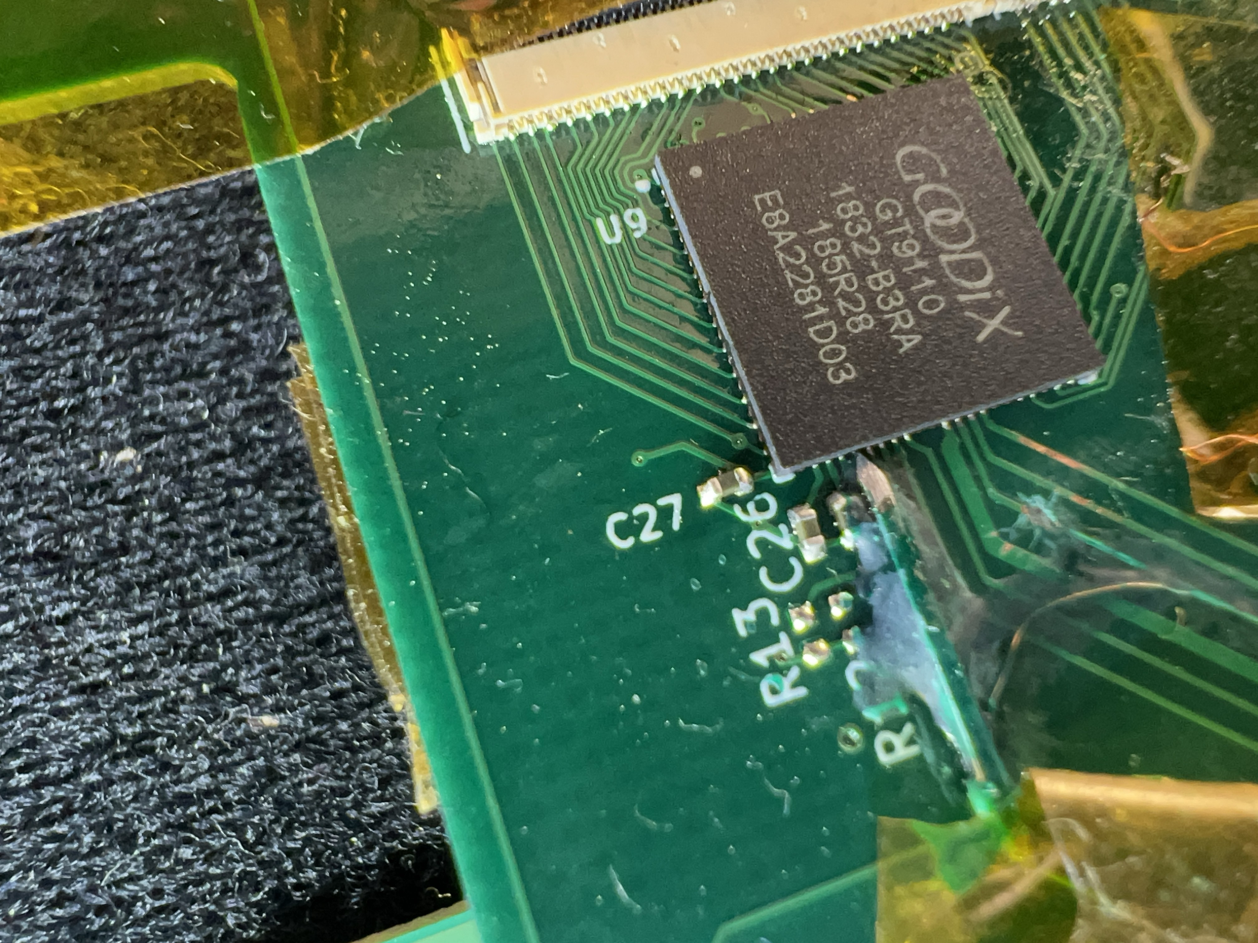
![]()
The GT9110 touchscreen controller, with the hack I had to implement to get access to the INT pin. First of all, the Linux kernel driver wants the INT pin from the controller to be wired to a GPIO pin. I hadn't connected that pin anywhere, and didn't leave myself any extra space on the pad to solder a wire to. I tried several things to bodge a connection to this wire before finding something that worked:
- poking an enameled wire at the edge of the chip and trying to get it to solder in place: the pins on the chip are visible on the side, but even my finest soldering iron tip is enormous compared to the 0.4mm between adjacent pins.
- removing the IC, soldering a 40AWG wire to the pad, and soldering the IC back down. It turns out, even 40ga wire is thick enough to keep the rest of the pads from reliably making contact when soldering. I still feel like I could've gotten this to work by adding more solder, but it was just too finicky, so I got frustrated and tried another approach:
- (what ultimately ended up working, mostly?) I took a standard 0.1" header pin, and used a file on 3 sides to sharpen it to a point that's flush with the 4th side. I then glued this in place with some UV-cure solder mask, which is my new favorite thing for bodges. Assuming you use a thin layer, it cures in like 10 seconds under the provided UV flashlight. This is what's shown in the photo above.
Another thing that I discovered was that I couldn't get the GT9113 to be discoverable on i2c at all. (The GT9113 has nearly identical pinout to the GT9110, but is meant to be used with a GTM802 companion chip, which I think is basically just a microcontroller.) I figured these chips would be basically identical, but maybe they're more different than their pinouts suggest.
After swapping the 9113 for the 9110, I was able to talk to it over i2c. However, I had a strange problem: the GT9110 wouldn't respond on the I2C bus for the first few requests made by the Linux driver. After that, it would respond fine. I'm not really sure what was happening. Maybe my GT9110 is bad? Maybe my bodged connection is marginal, so I've effectively made an RC circuit on the INT pin?
In any case, I'm pretty sure I'd be able to work around it with driver-level hacks, so I incorporated these changes into my PCB design:
- INT pin wired to a CM4 GPIO pin.
- Drop the traces for the GT9113's ARM_RST and Wake pins, since I'm committing to the GT9110.
Fit testing again
When I finally finished all of those routing changes, I made a new mockup using the same cardboard+printer paper technique as before. This almost fit, but not without some pressure holding the screen down (and flexing it slightly 😬). I discovered that the back of the screen was pressing against the button connector, and that I could make everything fit cleanly by moving that connector to the back.
![]()
My second cardboard+paper mockup in place in the iPad, with the CM4 and SSD mounted. In this photo, I've tucked the cable that goes to the buttons/switches behind the board, to test whether moving J4 to the bottom would improve the fit. With J4 on the back, it seems like everything would fit cleanly - the screen closed nicely, without requiring any pressure.
I rerouted the traces for the button connector (and moved some other traces from the back to the front to make room), added a bajillion tiny test points (0.25mm x 1mm) to the board - essentially replacing every NC flag in my schematic with a test point.
Ordering, assembly, and another fit check
At some point, I finally felt confident ordering my PCBs. (I also threw in boards for a quick side-side project). They arrived about a week ago, and I soldered together my prototype over the course of two nights:
![]()
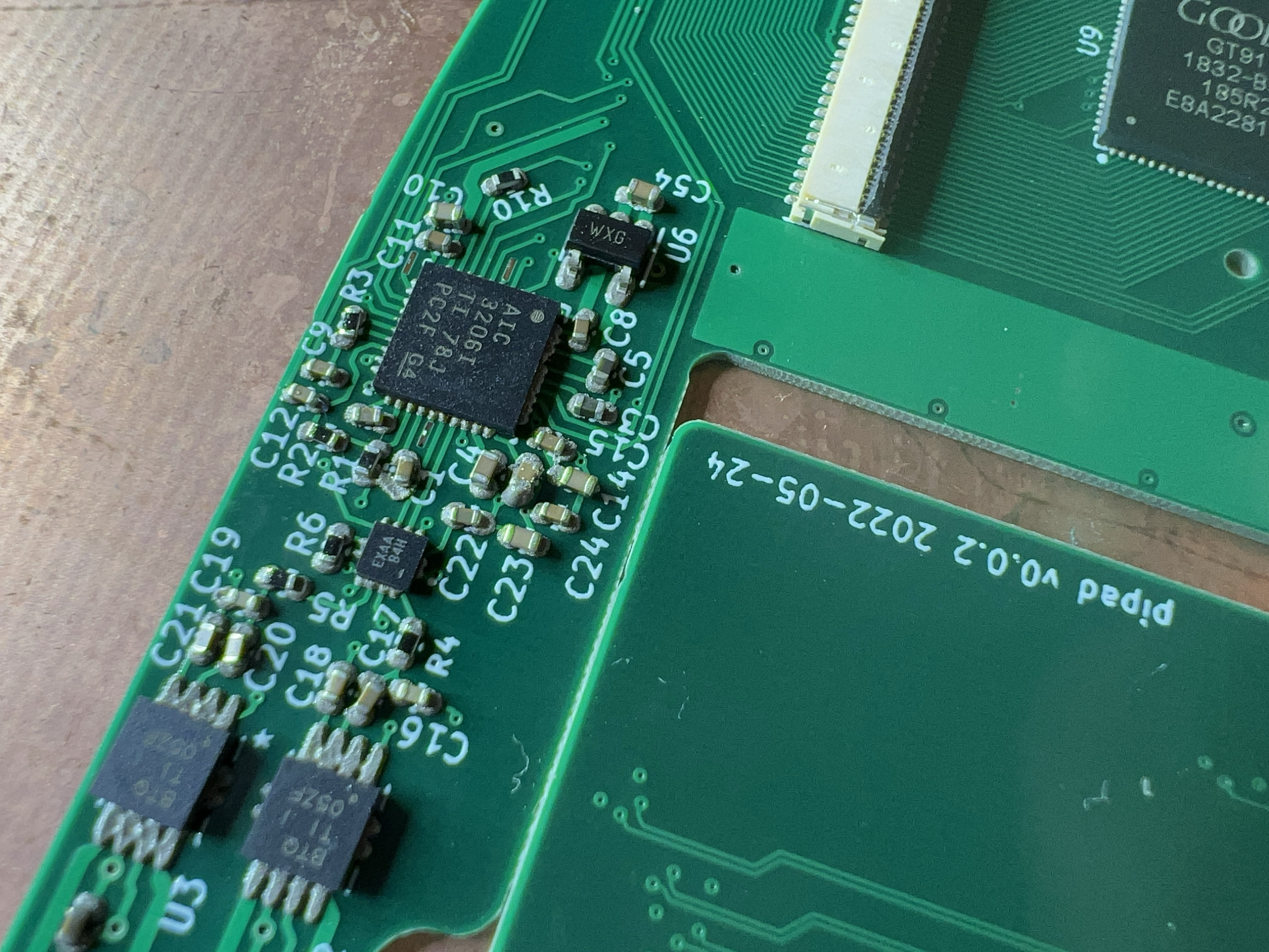
placing some supporting passives for the GT9110. ![]()
The audio codec components stuck to the solder paste, before reflowing. ![]()
All of the front components placed, ready for hot air. ![]()
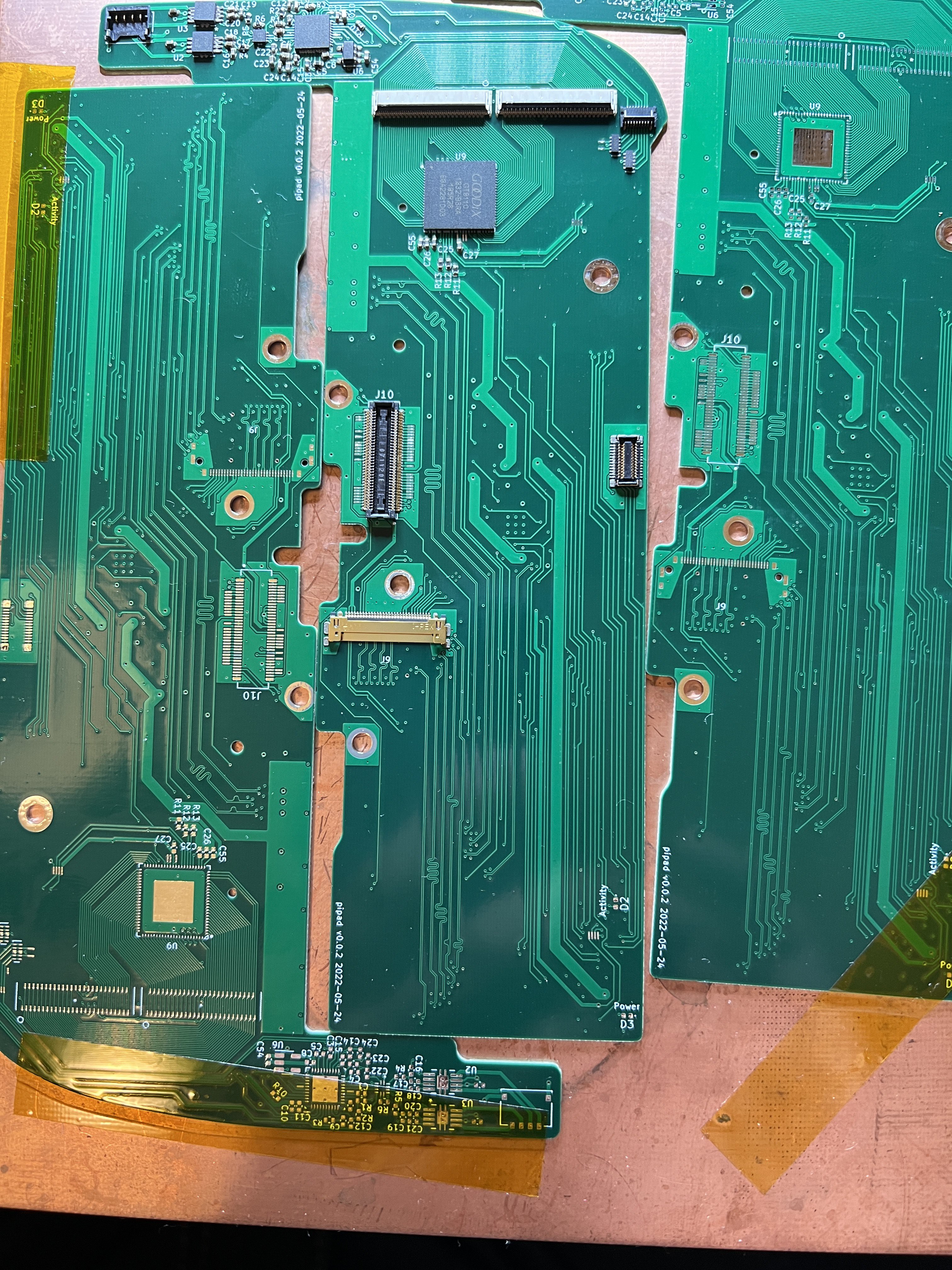
The back of the board, all soldered up, with the CM4 and SSD installed. ![]()
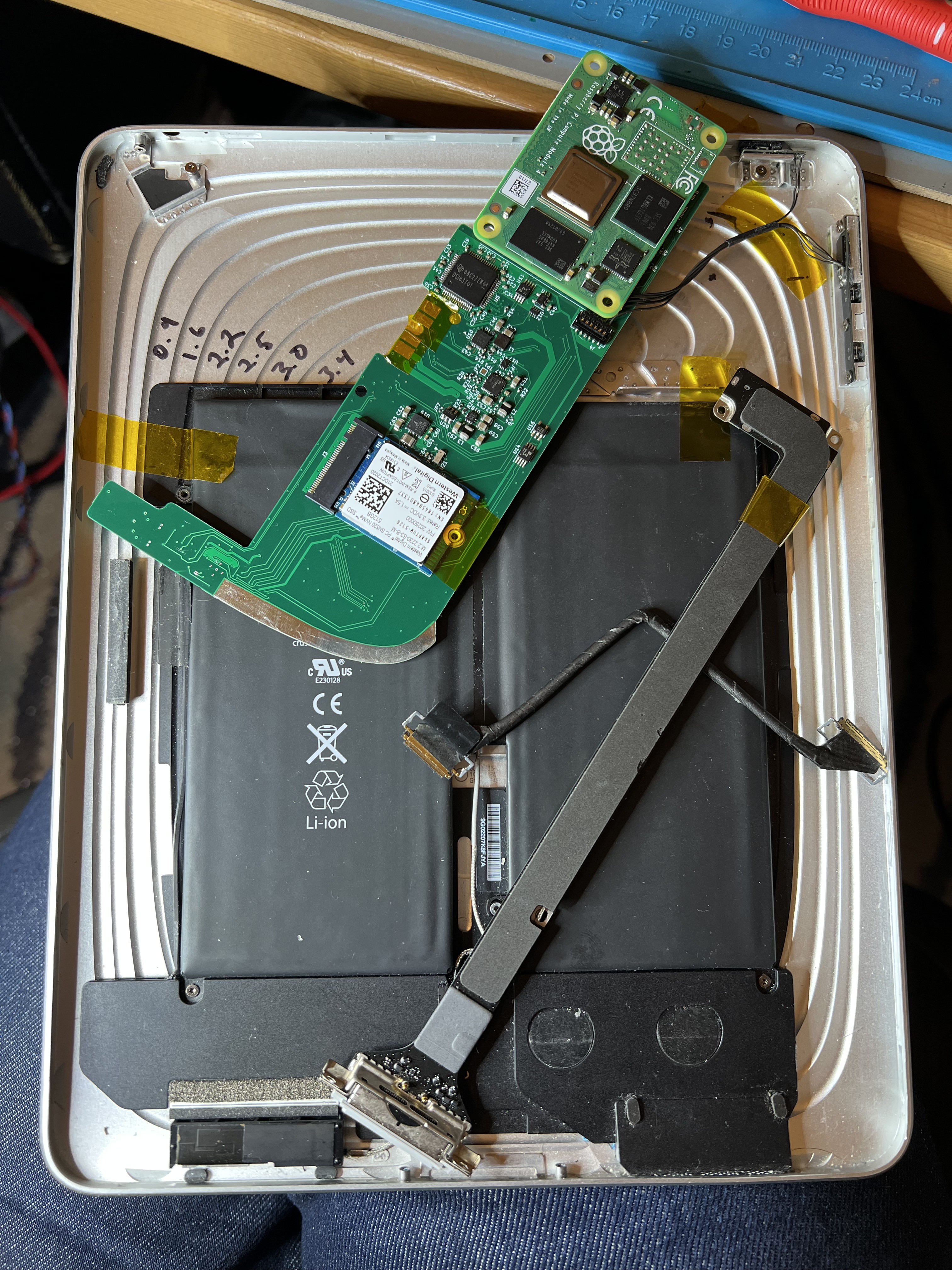
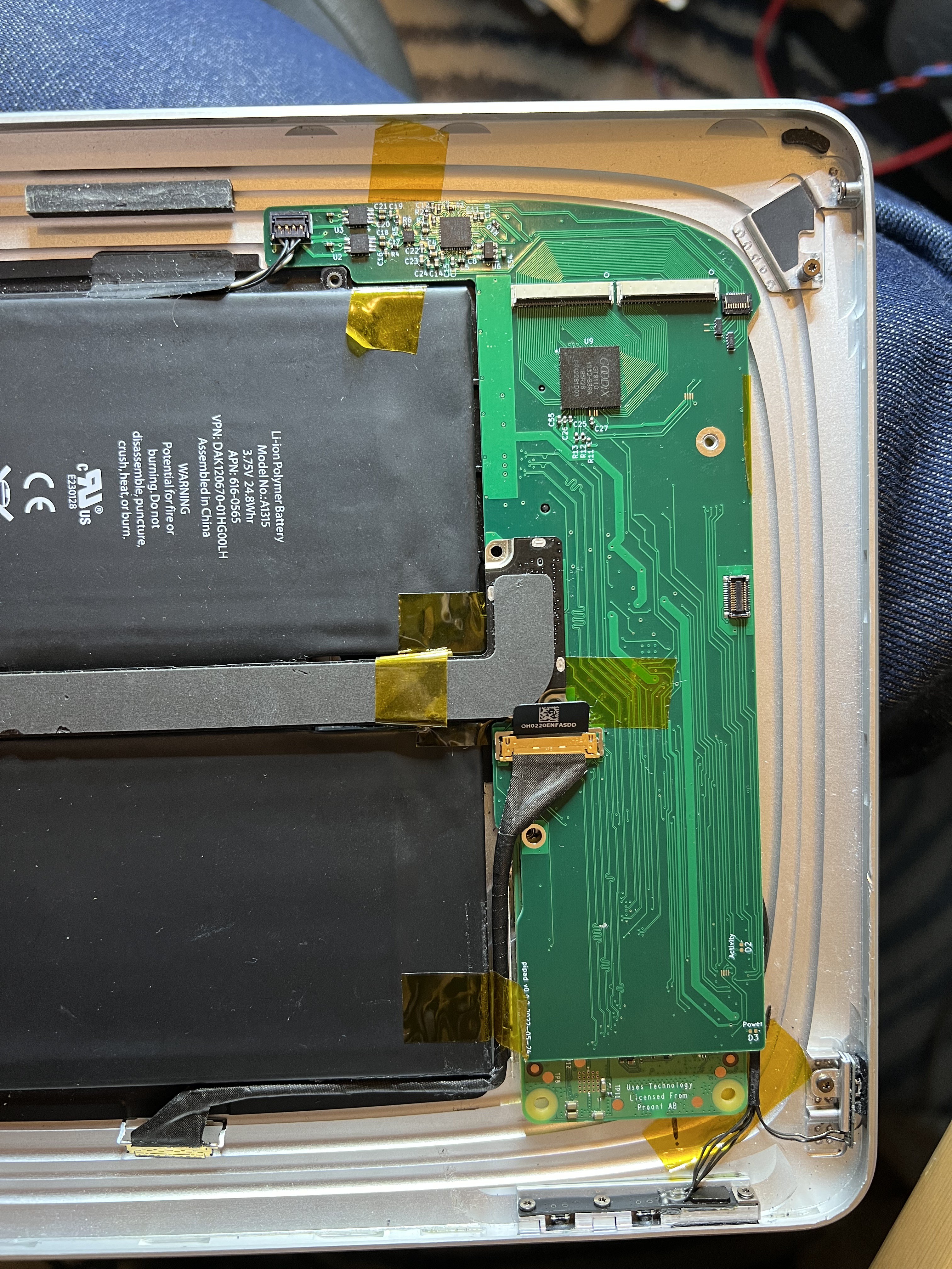
The board in its final position in the iPad, with buttons, speakers, dock connector, and LVDS cable attached. Only the touchscreen, ambient light sensor, and headphone port/microphone are missing. This almost fits. I think I didn't cut enough of the edge where the LVDS cable comes up -- that corner sticking out near the mounting hole is getting in the way a bit. Fortunately, there are no traces in that area, so I should be able to remove some material with a file.
Testing the new board
I've been testing this board, starting with the power systems: first, I tested the battery controller to make sure it still functions as expected: with 5V in, it will charge the battery; it puts out battery voltage on its SYS pin. Next, I checked the output of the 5V boost converter. This didn't work, which it turns out was because I hadn't installed a 0-ohm jumper between the battery controller and the rest of the board. Once I installed the 0-ohm jumper and applied power, some magic smoke came out:![]() It turns out I had the pinout of the TPS61177 wrong, which caused L1 to short 3.7V to ground:
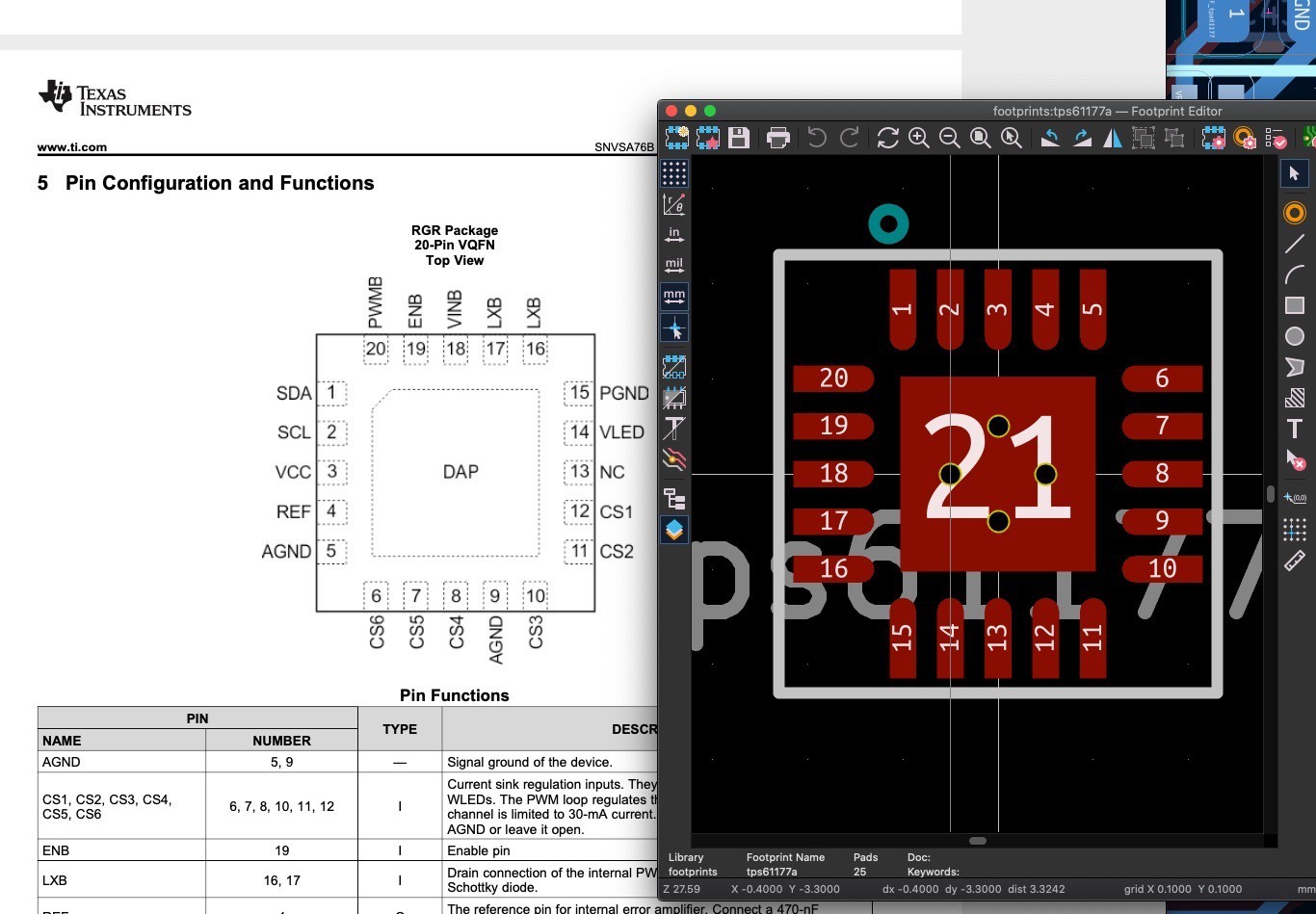
It turns out I had the pinout of the TPS61177 wrong, which caused L1 to short 3.7V to ground:![]()
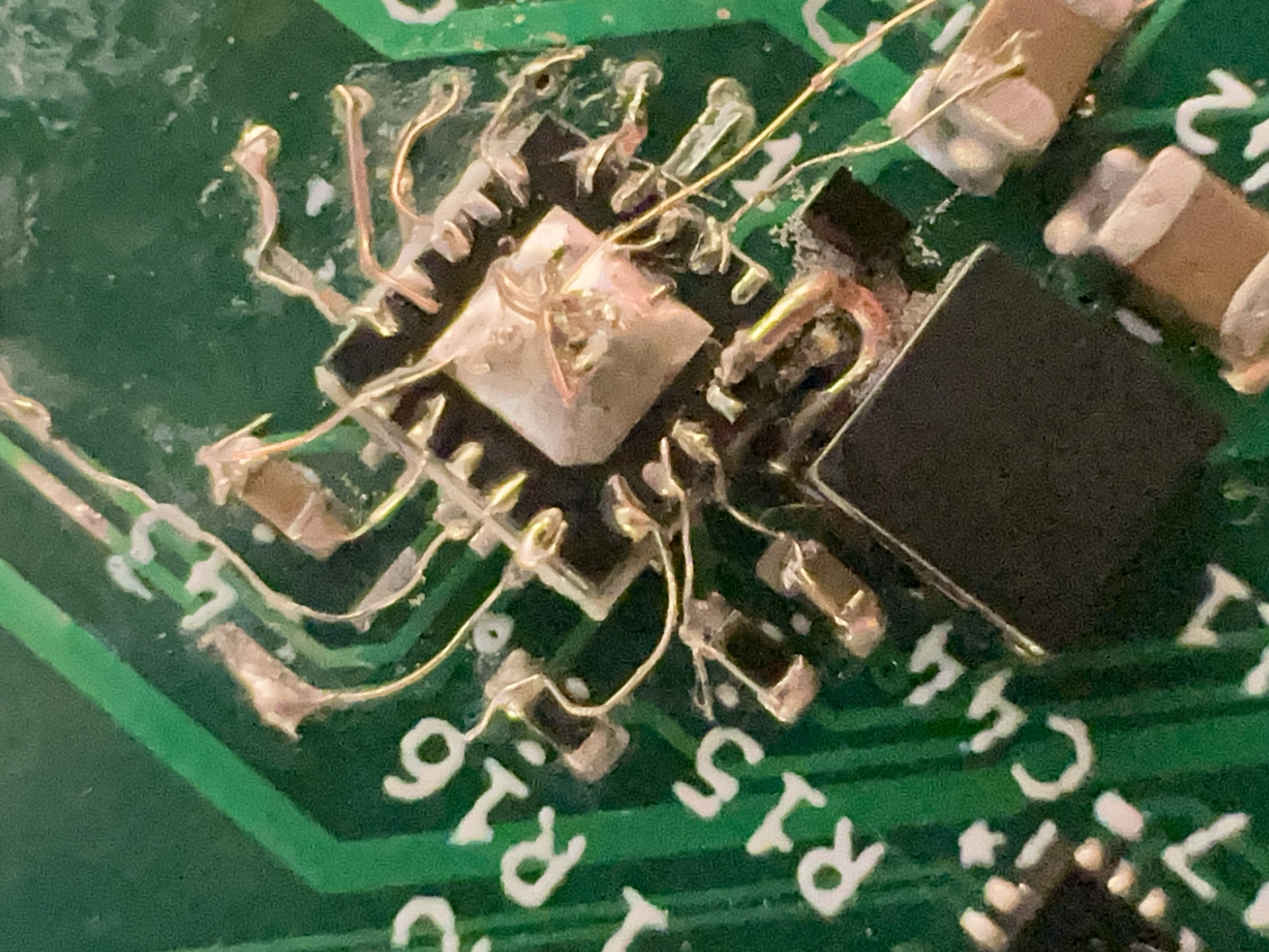
Whoops- my footprint has pins 1-20 going clockwise around the chip, where the actual chip goes counterclockwise. Essentially, I mirrored the footprint for the TPS61177. I have attempted to fix this by flipping the chip upside-down and painstakingly bodging wires to nearby components and traces:
![]()
(I also replaced the inductor and IC with fresh components.) When applying power, this no longer tries to draw 9 amps. Will it actually work? I won't be able to test this until I can get something (preferably the CM4) configuring it over i2c and giving it PWM input.
Can this actually run the CM4?
After verifying that I have what seems to be a stable 5V rail, and nothing else trying to catch fire, I enabled serial console on my CM4 while it was still on the CM4IO, tested that it worked with a USB-TTL adapter I had lying around, then anxiously moved the CM4 over to my board.
Applying power, I get nothing on the serial port. 5V and 3.3V rails seem stable...
I soldered an LED and resistor between 3.3V and the activity LED pads (I need to adjust my schematic for the activity LED -- I had just put the LED between the activity pin and ground, but it's an active-low, open collector pin.).
The activity LED flashes a few times -- when looking at the voltage on it with my logic analyzer, it seems like there's actually a ton of activity at first; but still, no output on the serial port.
I moved the CM4 back to the CM4IO to verify that serial output was still working there, and at one point I used my multimeter to probe the GPIO pins to verify that I had the GPIO pins in the correct orientation. While probing the 5V pin, my probe slipped, and shorted 5V to 3.3V! The CM4 is now dead 😢.
I have ordered a new CM4 from Welectron, a German distributor, since that was the only place that had any CM4s in stock according to rpilocator. One silly slip of a multimeter probe has cost me 64 EUR and a week or two of waiting for the replacement to arrive.
(The internet suggests I might have just damaged the PMIC on the CM4, and that I might be able to repair it by replacing the MXL7704 chip, so I'll be ordering some of those from AliExpress soon, but those will likely take longer than the replacement CM4 to arrive. EDIT: this source claims theMXL7704-P4 on the CM4 is different than the -R4, and isn't compatible: https://forums.raspberrypi.com/viewtopic.php?t=322613)
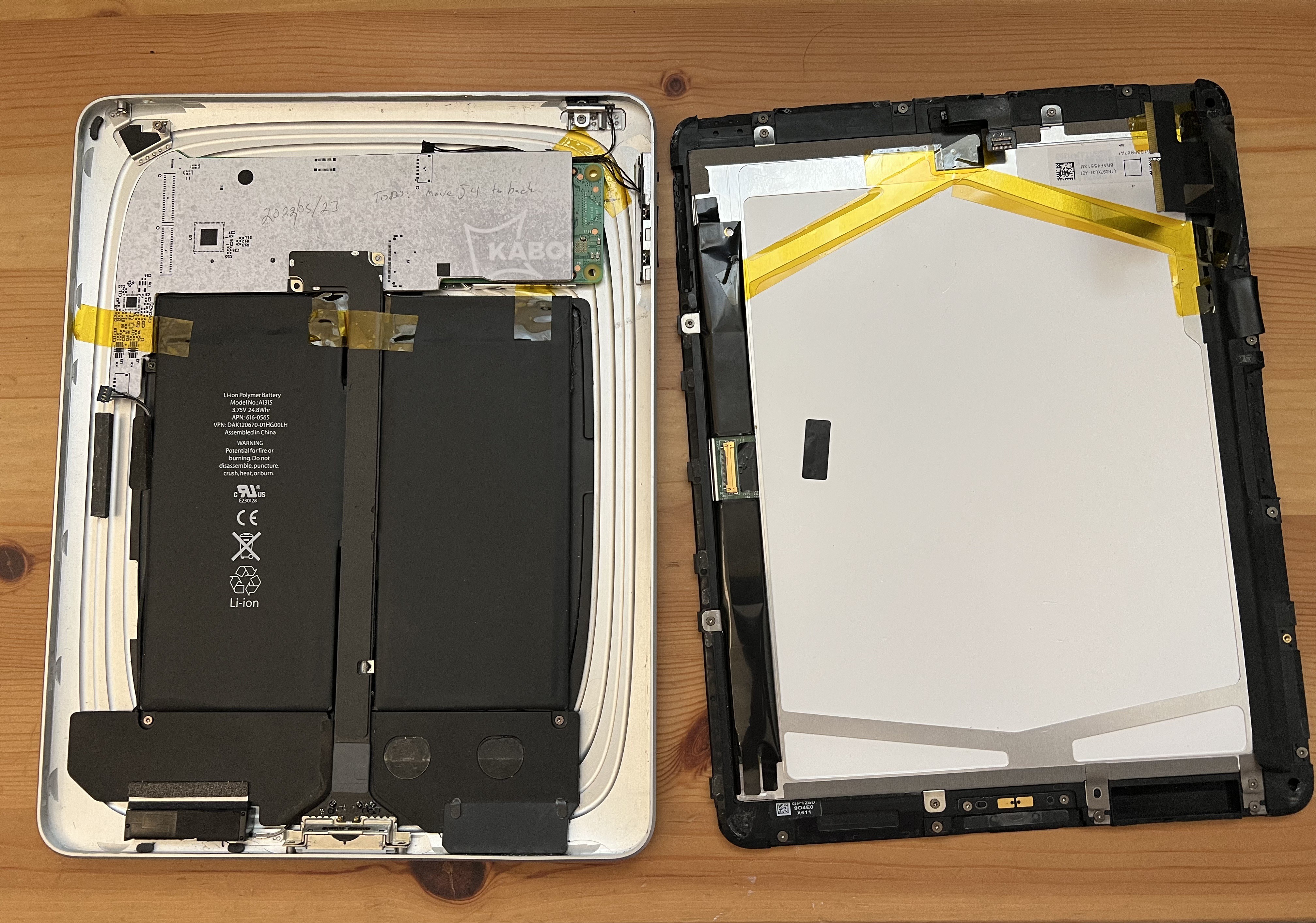
[HDP 2022] Put an RPi CM4 into an original iPad
Open up a 2010 iPad, remove its logic board, and fabricate a new board based around the Raspberry Pi CM4.