-
Contest entry video
10/23/2022 at 13:47 • 0 commentsHere is an updated video that shows the working machine and all of its new functionality, including USB storage and internal Wi-Fi card:
-
Configuring USB storage access and Wi-Fi setup
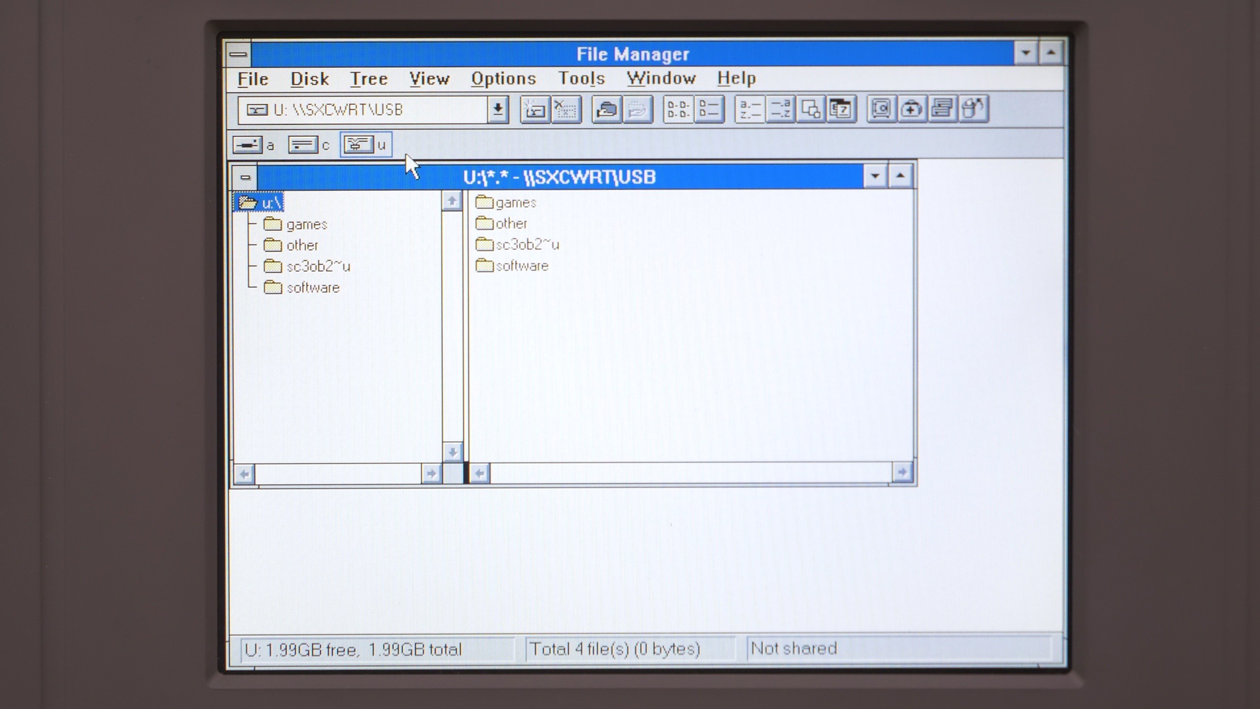
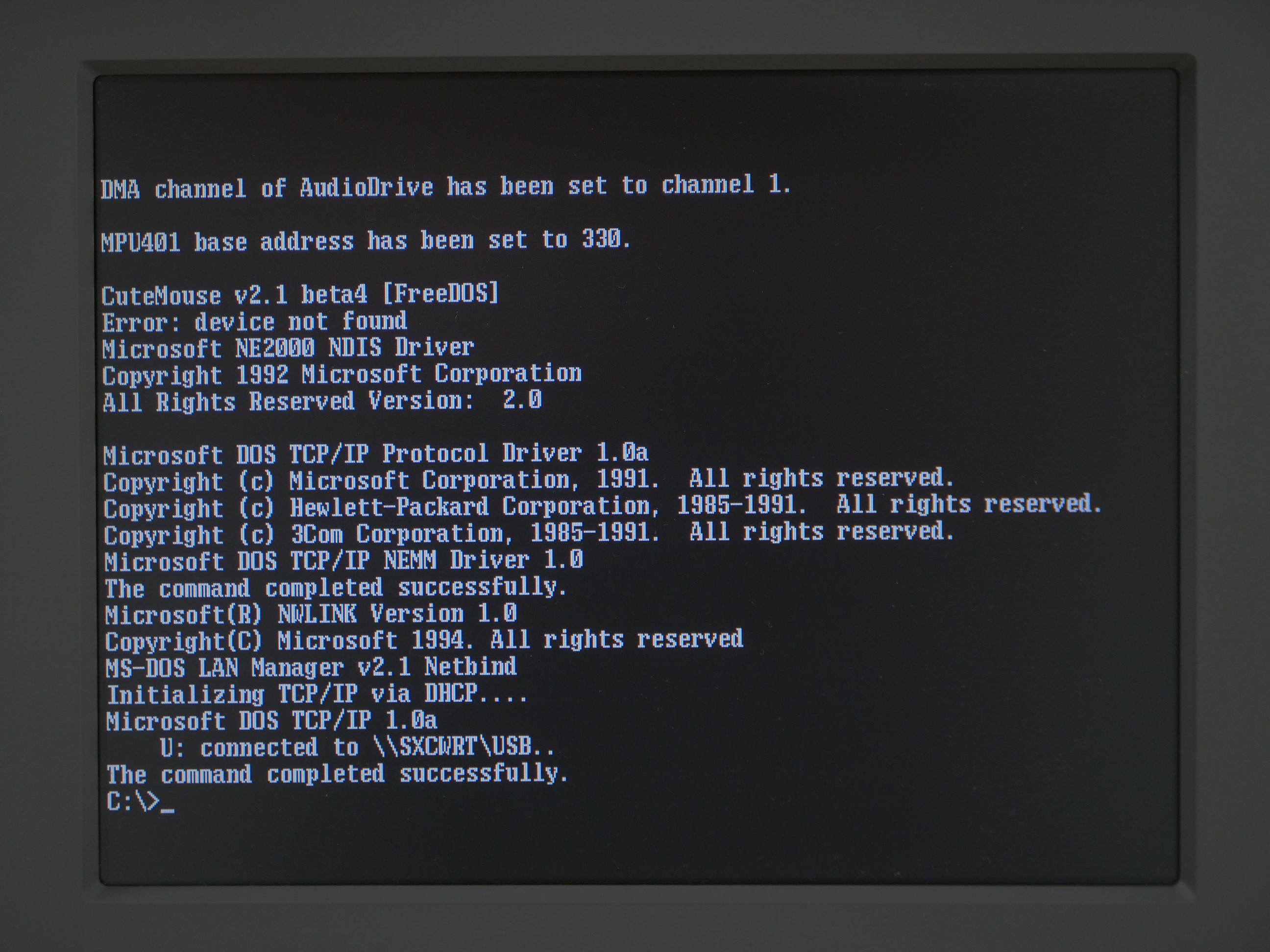
10/23/2022 at 13:30 • 0 commentsI managed to successfully configure USB storage access. The USB drive can be plugged directly to the expansion card installed in the laptop. It wil be seen as a network drive on both the MS-DOS and Windows 3.11. For Windows 3.11, built-in networking options can be used. For MS-DOS, Microsoft Client for Networks for DOS needs to be installed (it used to be distributed through official Microsoft FTP servers).
![]()
![]()
![]()
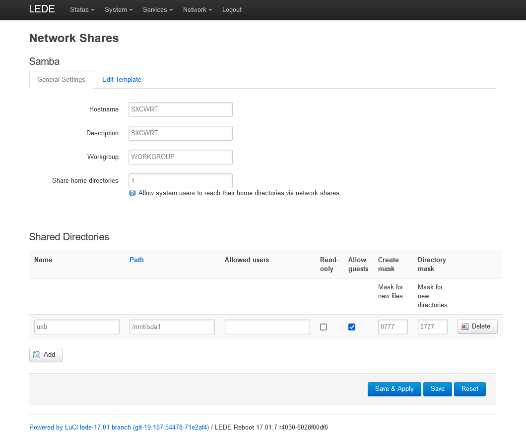
On the OpenWRT router module, a Samba36 server needs to be installed. It also needs to be configured with additional "server min protocol = NT1" option, to allow the connection with legacy clients, like MS-DOS and Windows 3.11.
![]()
To install OpenWRT on this module, I used instructions published on the OpenWRT website: https://openwrt.org/toh/unbranded/a5-v11
However, in order to use USB storage network sharing, I needed to install additional modules. Therefore I desoldered the original 4MB SPI flash chip, copied the firmware, burned it to a new 16MB chip, soldered it back, and then upgraded the firmware with a 8MB (sic) OpenWRT build that I got here: https://archive.openwrt.org/releases/17.01.7/targets/ramips/rt305x/lede-17.01.7-ramips-rt305x-m4-8M-squashfs-sysupgrade.bin
This 8MB image is targeting a slightly different device, but worked completly fine in my case and I didn't have to compile a special version for my device.I placed configuration files, scripts and more detailed description of the software I used in the external GitHub repository: https://github.com/adbrt/dos-wifi-solutions/
-
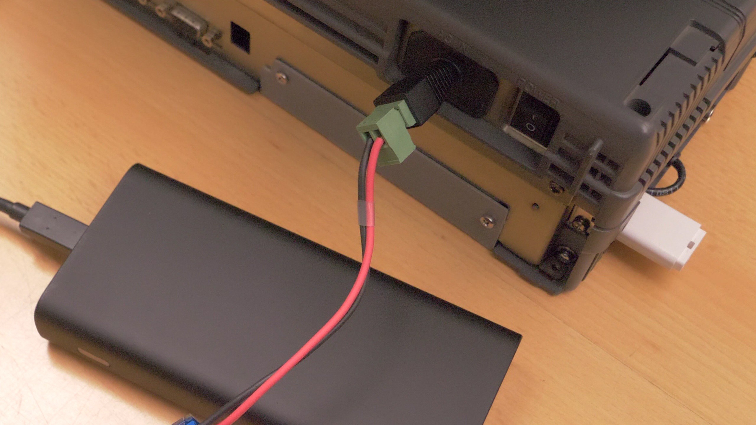
Powering with USB-C
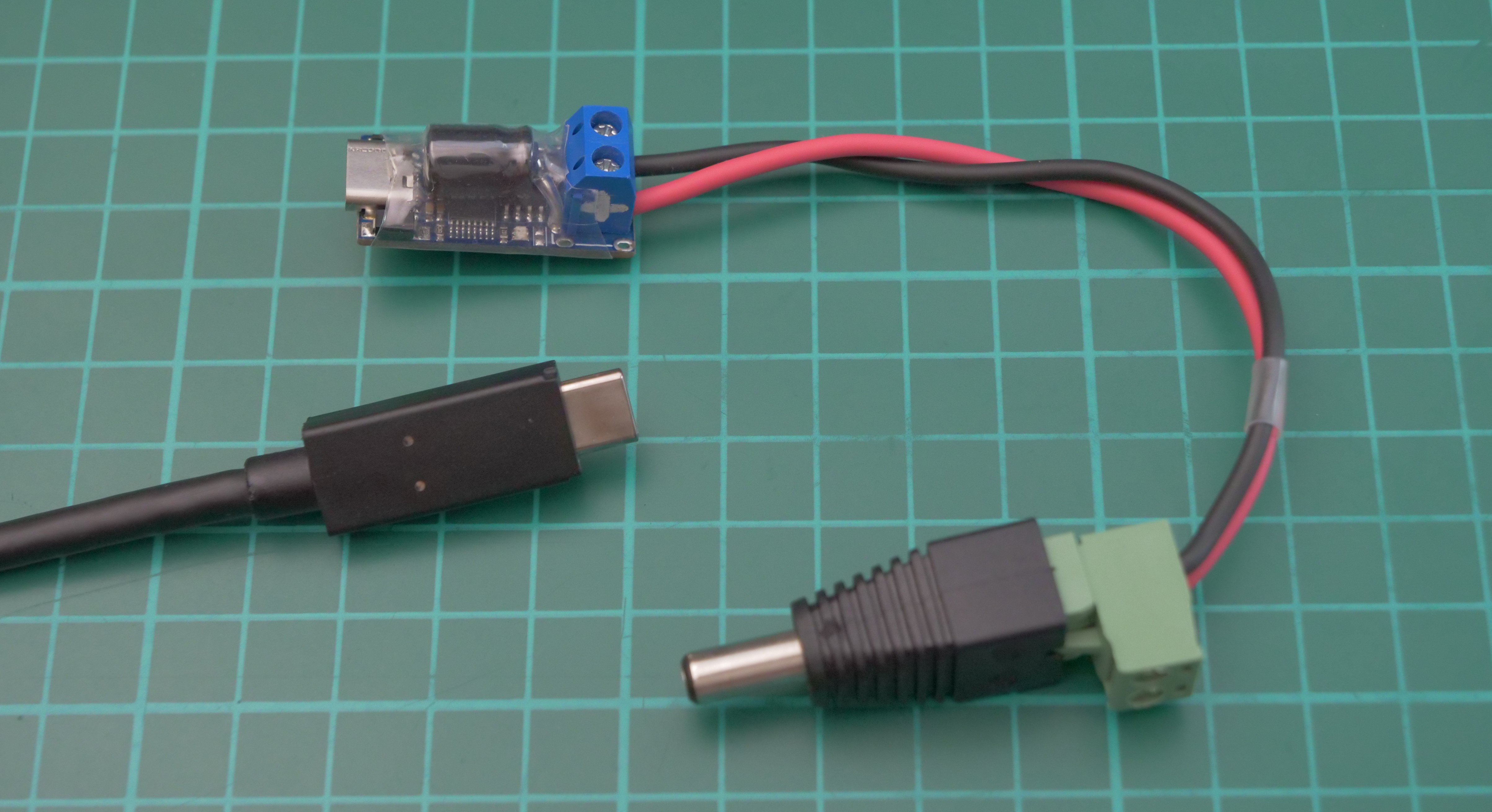
10/23/2022 at 12:57 • 0 commentsBecause this laptop now uses a DC-DC power supply, it can be easily adapted to USB-C, which allows to run it off USB-C powerbanks. It would be even possible to use USB-C as the default connector, but that, in my opinion, would would look weird in such an old machine. Therefore I added a panel-mounted barrel jack in the power supply enclosure, and used USB-C adapter to power it from USB-C instead of barrel jack, if needed.
To run it off USB-C, a small module called "USB-C PD trigger" is needed. They are easily obtainable in various places. One with 15V or 20V pre-set voltage is needed (this laptop accepts wide input voltage range). It might be necessary to also solder a small low-ESR capacitor between the output terminals, because otherwise the initial inrush current may cause the powerbank to shut down. I added a 25V, 330uF Panasonic FR capacitor.
![]()
![]()
-
Why was this laptop's screen a big deal
10/22/2022 at 22:31 • 0 commentsIf we put the repair/restoration things aside for a moment, it might be worth explaining what was so innovative about TFT technology used for the first time in this laptop, over 30 years ago.
Color LCD screens did exist before this laptop was created, in the form of of passive, or Dual Scan Supertwist Nematic screens. And, unfortunately, the image they produced was absolutely awful, especially when there was any kind of motion on the screen. The ghosting was so bad, sometimes even several seconds long, that these screens were completely unusable for multimedia tasks or games. The colors, contrast and image brightness uniformity was also really poor. I had experience with old DSTN laptops and I can confirm that they were really bad. Even using mouse could be a problem, because the cursor would usually be invisible during motion, because the screen couldn't refresh the image quickly enough.
Currently I don't have a DSTN screen that I can use to show a comparison with TFT, but I simulated one, by post-processing a recording of TFT screen and adding ghosting artifacts (which in real life could be even worse than that) and modifying the colors and lighting, according to what I remember from my experience with DSTN screens. If you have never seen a DSTN screen before, this should give you an idea what is the difference, and how much of an improvement was the TFT technology.
![]()
Difference between DSTN (simulated) and TFT. Game is Prehistorik 2. -
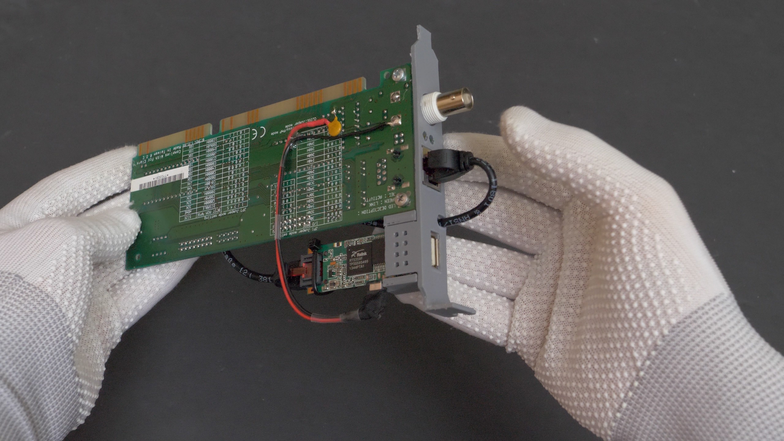
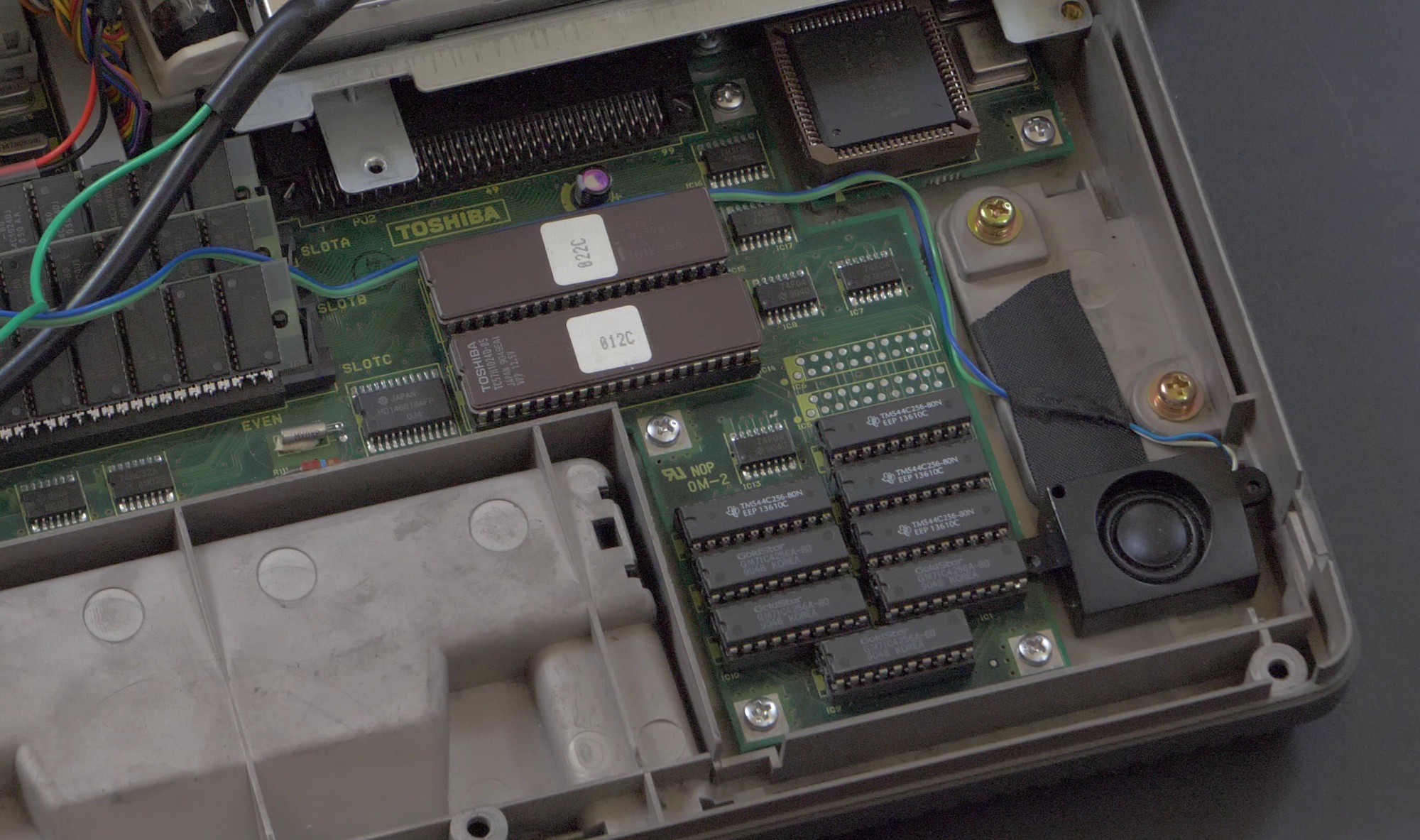
Making ISA WLAN + USB storage card
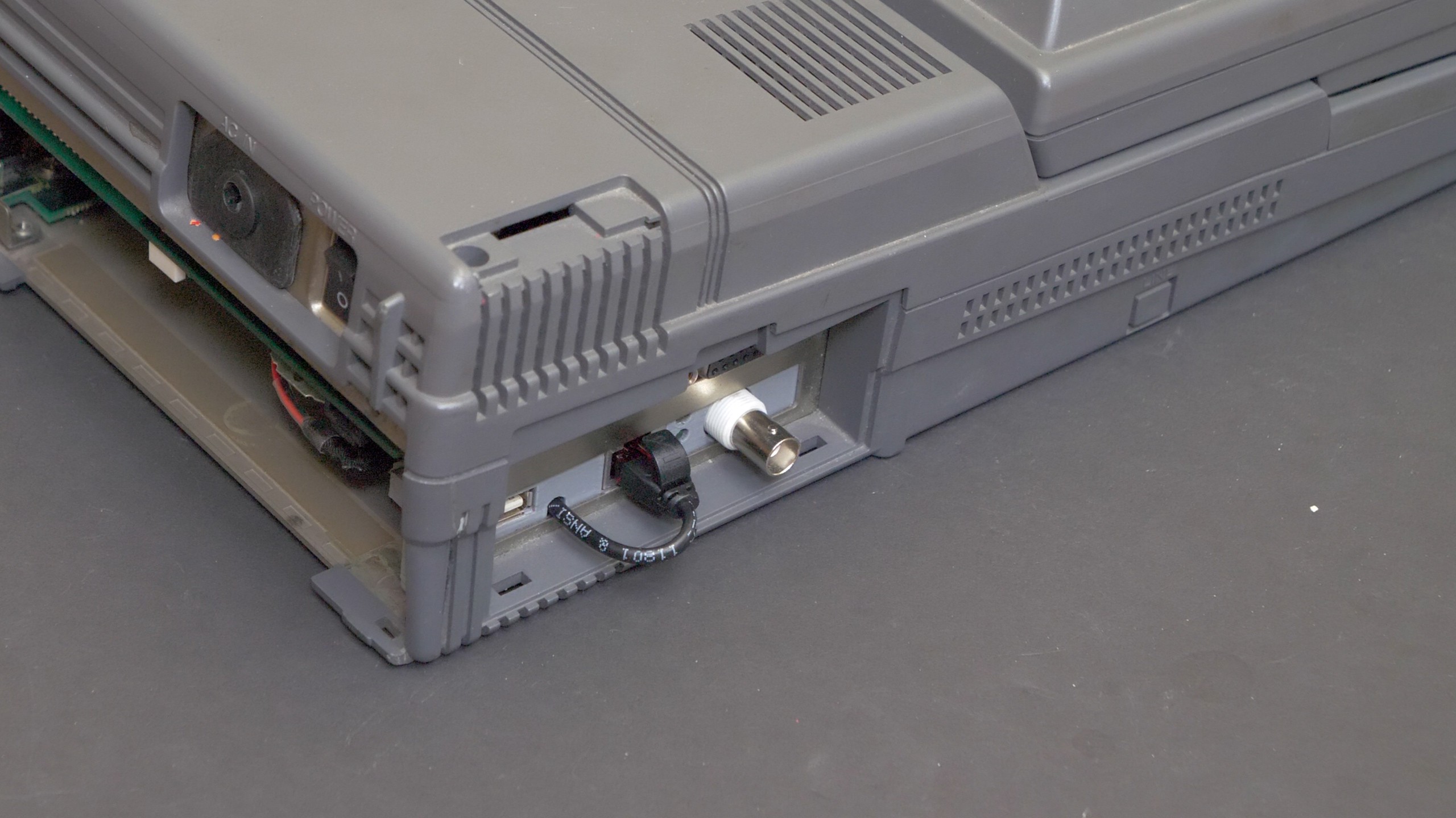
10/22/2022 at 22:03 • 0 commentsI completed the work on an integrated WLAN + USB storage add-in card for this laptop. It was made by using an old, generic NE2000-compatible LAN card, replacing the steel bracket with a 3D-printed one that can hold the mini-router module and expose the USB port.
The router just plugs via thin and short RJ45 cable. I could have soldered the cables directly and kept them inside of the device, but that would make the device more difficult to repair/upgrade in future. Now the additional WLAN module can be easily plugged and unplugged. It's also possible to unplug WLAN at any time and just plug wired Ethernet, if needed.
Power to the WLAN module is provided via micro-USB connector with other end soldered to +5V and GND pads on the ISA card. I added a polymer fuse in series, to protect the computer in case of a short-circuit.
![]()
![]()
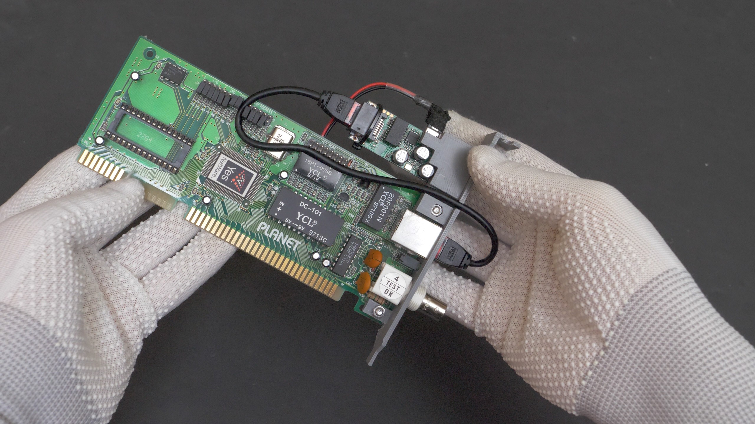
This is all that is needed to get the machine on the wireless network. The entire module can be plugged into the laptop's ISA slot, a packet driver for the ISA card needs to be loaded and the laptop will think, that it is connected to a wired network. But it is wireless in fact, and that small, modern mini-router module act as a wireless bridge.
![]()
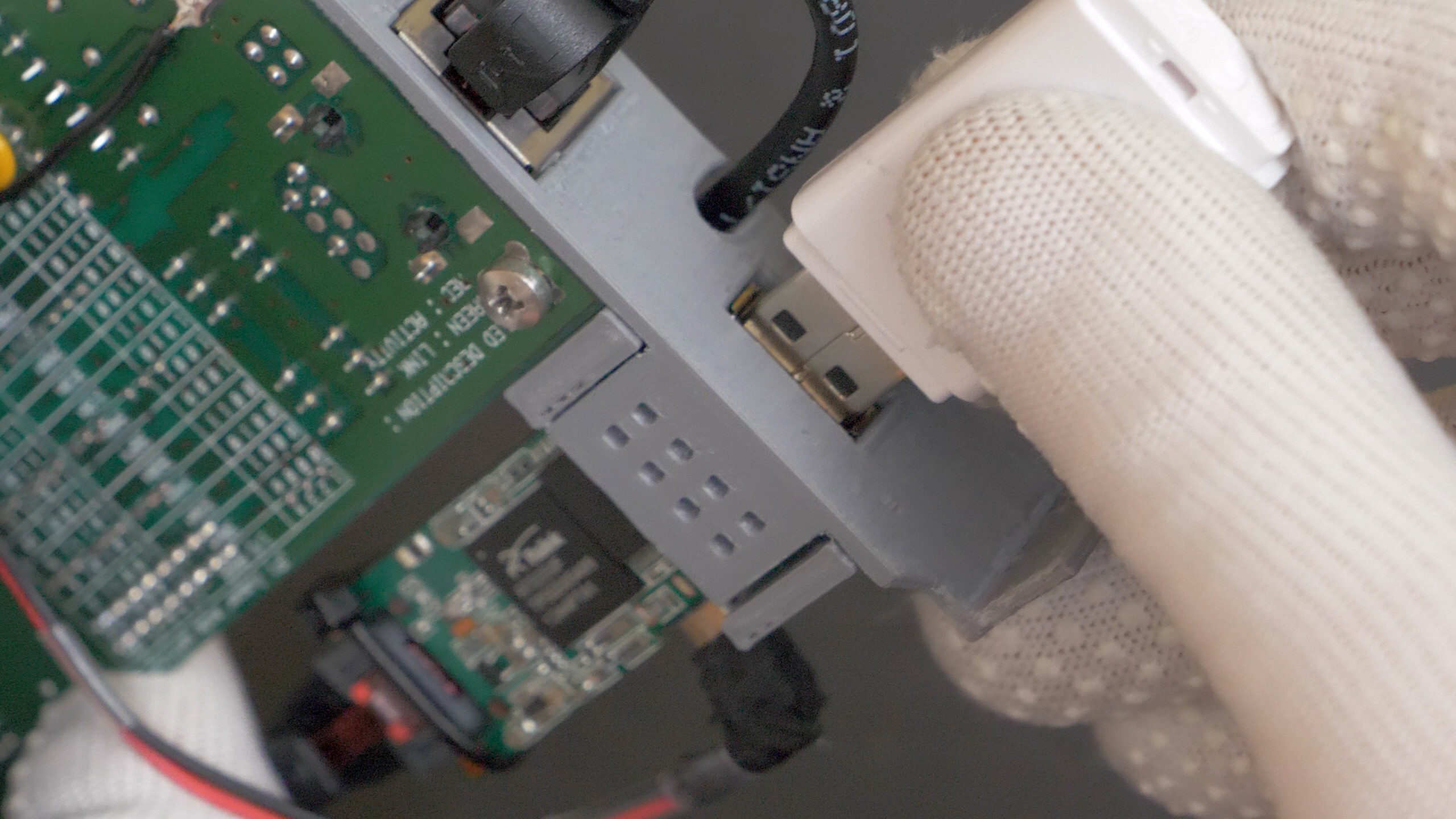
Now I just need to figure out the best way to utilize the integrated USB port. I want the laptop to be able to access files from USB drives. This should be possible if I configure a Samba network-sharing server on OpenWRT firmware, and use Microsoft Network Client on MS-DOS or Windows 3.11. Files would be then bi-directionally shared over the network between the USB drive and the laptop.
![]()
-
Ideas on how to use it
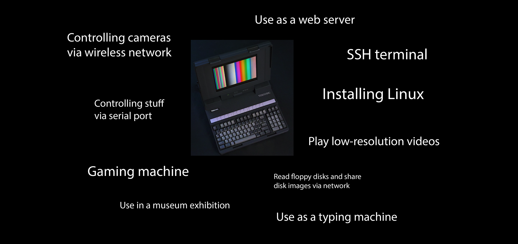
07/23/2022 at 23:30 • 0 commentsI'm trying to research some potential cool uses for this machine. Will try to look for more and evaluate them in practice.
![]()
-
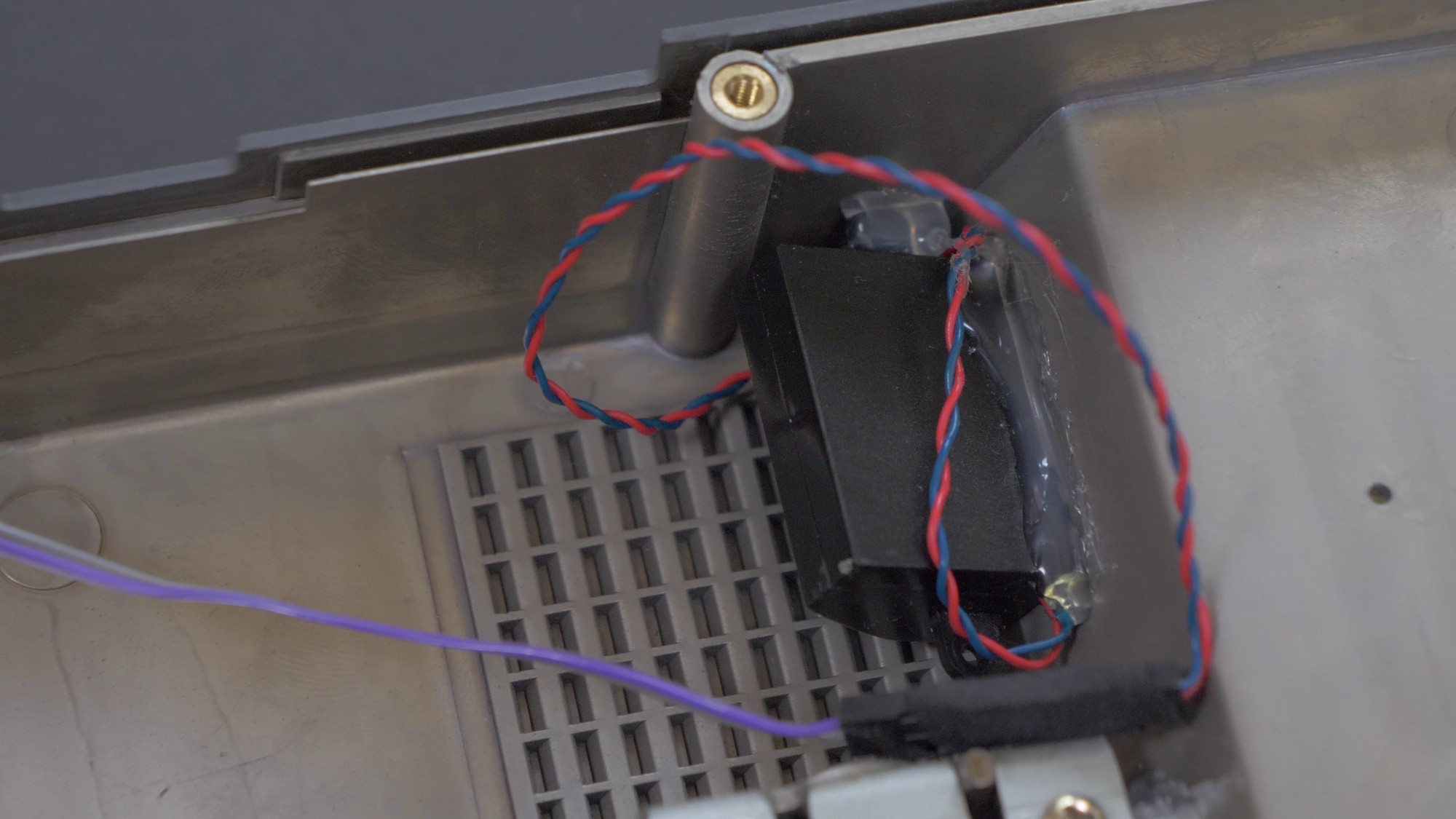
Installing speakers and a sound card
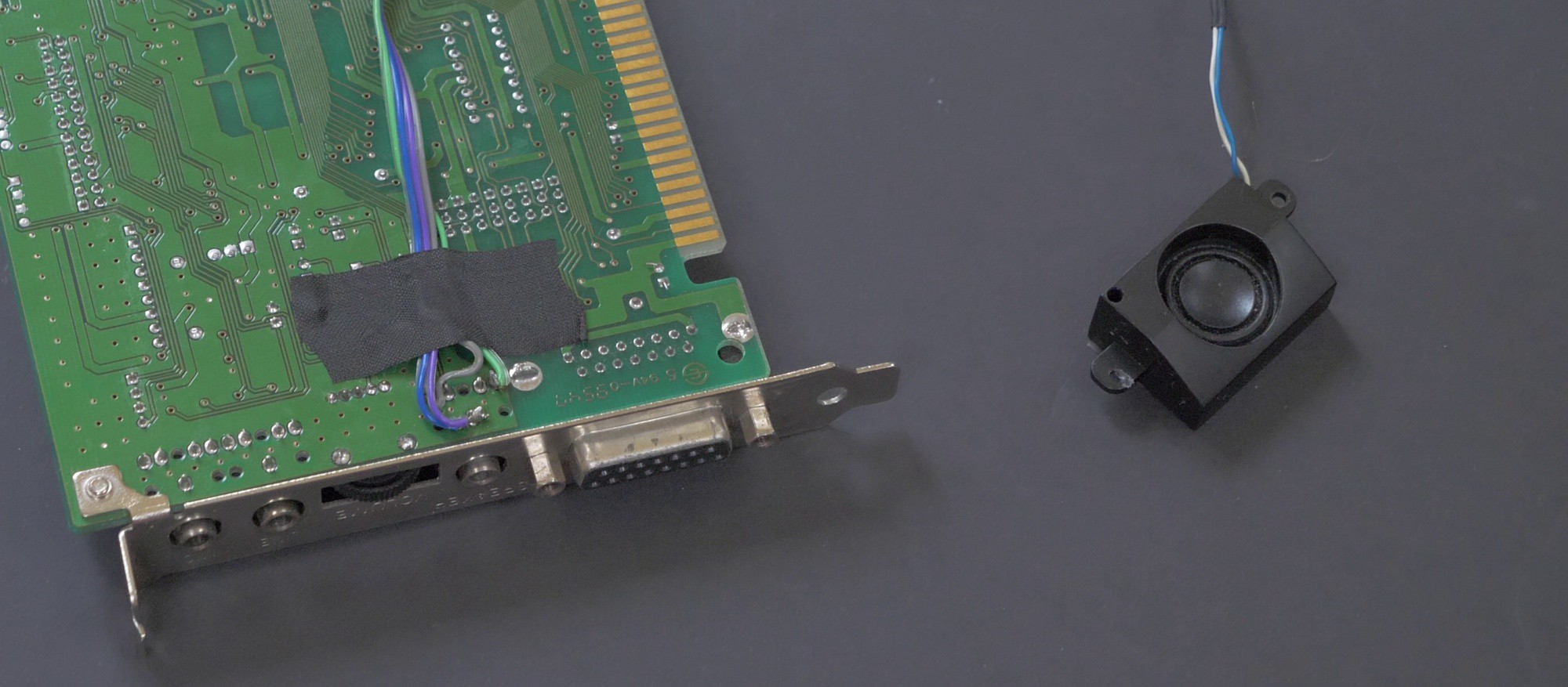
07/23/2022 at 23:28 • 0 commentsI managed to fit small stereo laptop speakers in the case. I just soldered some wires directly to the sound card (but I included a connector on the cable, so the speakers can be easily unconnected if needed).
![]()
![]()
![]()
-
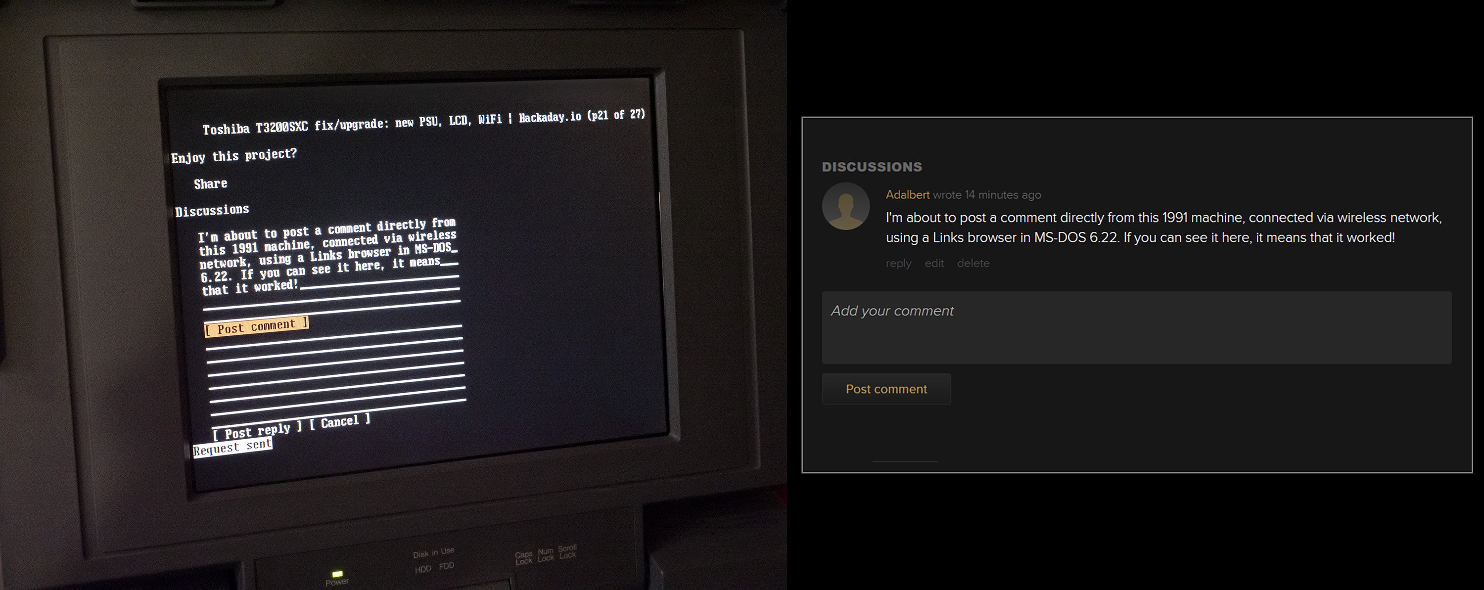
Getting it on wireless network
07/23/2022 at 22:30 • 0 commentsIt turns out that this 16MHz machine is quite capable, as I managed to connect it to wireless internet and post a comment on this very page:
![]()
I used a tiny A5-V11 router with RT5350F SoC: https://openwrt.org/toh/unbranded/a5-v11 that I flashed with OpenWRT. Currently I am connecting it externally to the ISA ethernet card attached to T3200SXC, however I plan to embed this tiny OpenWRT module directly onto the ISA card. This is how it would look like piggybacked:
![]()
It uses just around 1-2 watts of power, so I plan to find a suitable soldering point with +5V on the wireless card and solder wires in series with a small polymer fuse. The ethernet wires will need to be soldered between these two cards - i may desolder the RJ45 connectors completely. To avoid blocking the wireless signal, metal bracked will need to be replaced with a 3D-printed one.
On the software side, I prepared some scripts for both the MS-DOS machine and OpenWRT router, that allow for very simple scanning and connecting to the networks directly from MS-DOS. Details will be stored in this repository: https://github.com/adbrt/dos-wifi-solutions/
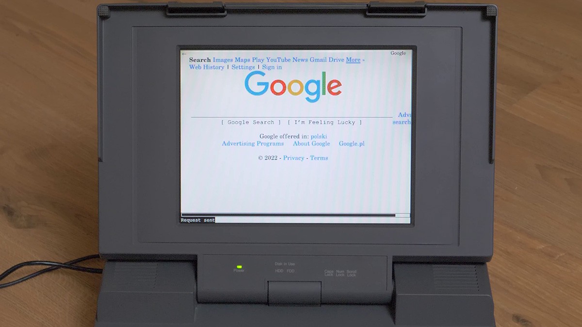
For a web browser, I'm using Links for DOS: http://links.twibright.com/download.php
It supports TLS 1.2 and it even has a graphical mode! However it slows things down quite a bit:
![]()
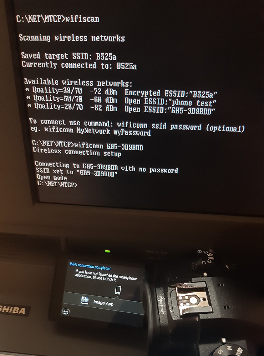
I also managed to connect to a Wi-Fi control interface of a digital camera (Lumix GH5). The camera detected that the connection has been estabilished. I wonder if I could take some photos, download them to the DOS machine and upload them online using HTTP interface of the camera. I will need to look into the protocol and try some things out. You can see here how the wifi scan / connect command works:
![]()
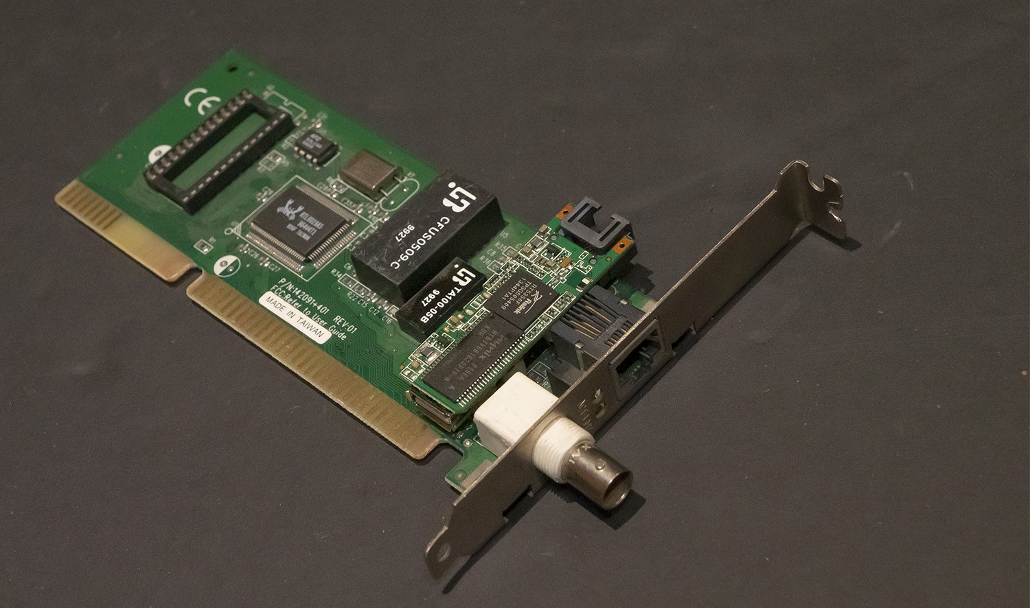
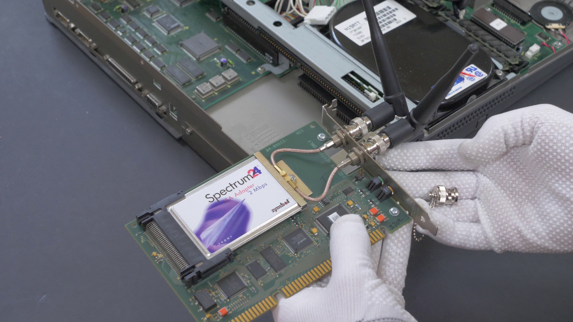
By the way, as a bonus, I will mention that old-school ISA 2.4GHz wireless networks adapters did exist, and in fact here is one that I tried to use with that computer!
![]()
However it is completely incompatible with modern Wi-Fi protocol - so it wouldn't be much of an use. Therefore I'm going with the embedded OpenWRT module option.
-
Replacement power supply
07/22/2022 at 14:55 • 0 comments and new, smaller power supply (bottom)")
Old (top) and new, smaller power supply (bottom) A prototype power supply was fabricated using mostly readily-available DC-DC modules and home-etched PCB made by exposing a board coated with UV-soldermask under a 3D-printed mask.
The power supply required following rails:
- +12V for mainboard/HDD
- +12V for LCD with turn on/off signal
- +5V
- -5V
- -12V

Schematic of the new power supply 
Preparing PCB for etching by spreading UV-curable soldermask and exposing it under 3D-printed mask 
New power supply I described the process of creating a PCB for this power supply in this project: https://hackaday.io/project/186467-making-pcbs-with-3d-printed-stencil-and-uv-paint
and in this video:
Major components of the power supply:- D24V22F12 12V 2.2A step down converter x2
- D36V50F5 5V, 5.5A Step-Down converter
- LC-MC34063A-NV negative voltage converter module
- LM7905 -5V negative voltage stabilizer
- 5V and 12V SMC and SMB TVS diodes for rudimentary overvoltage protection
- 5A polyfuse
- 250mA polyfuse
- low ESR capacitors, ceramic capacitors
The power supply will be able to operate on wide input voltage range (ca. 15-24V), as all of the voltage rails are generated using step-down converters. It could be more cost effective to use just 5V and -5V, -12V converters, and use +12V directly from the DC input, but that would require some additional, active overvoltage protection, as it would be much easier to mismatch the power supply. It would be also possible to use just one +12V converter if a mosfet would be used to power the LCD on/off, but two converters were used to spread the load. ENABLE pins of +12V and +5V converters were used to provide soft power on-off functionality and to allow switching the LCD on and off (with help of additional transistor).
-
Replacement LCD and signal adaptor
07/22/2022 at 14:01 • 0 commentsI wanted to connect replacement LCD to the original LCD connector, with no "ugly hacks" like interfacing with VGA connector and other workarounds. The original LCD used 9-bit TTL RGB interface (3 pins for red, 3 pins for green, 3 pins for red), which understandably is quite dated, especially considering the fact that this was probably the first laptop with color TFT screen.
I was able to only source replacement screens with 18-bit RGB interface (i chose Sharp LQ104V1DW01), with much slimmer outer casing (but the same screen area and resolution). Therefore I needed to adapt new screen both electrically and mechanically.
The original interface had 8 possible values for each color (0,1,2,3,4,5,6,7, or 000 to 111).
On new LCD, there are 64 possible values for each color (0 to 63 or 000000 to 111111).
The idea was just to ommit half of the R, G, B pins. The lower pins (RGB0,1,2) on new LCD would remain unconnected. The upper pins (RGB3,4,5) would be connected with RGB0,1,2 from the computer. Now the maximum value for each color will be 111000, which is 56 out of 63. That limits the maximum brightness of the screen to 89%, but this should not be a big deal.

Schematic of the LCD adaptor There are also UD (up-down), RL (left-right) pins on the new LCD, which can be pulled either to ground or VCC. They can be used to rotate or mirror the image. I left them floating, however a option of jumpering them remains if ever needed.
A prototype was produced using a single-sided home-etched (laser toner transfer) PCB, with 2.0mm 28pin header and directly soldered 0.5mm 32-pin ribbon. Because the board was single sided, it required a bit of jumper wires. The screen did work and I partially potted the PCB in epoxy.

Prototype of LCD adapter. Two additional wires were routed only because I damaged two pads on the adapter. The backlight inverter also needed to be hacked, as I didn't have a matching one for the new screen, and I couldn't use the old one. There was no brightness level signal on the T3200SXC, so I had to connect EN pin with ADJ pin. That way the backlight was on as soon as +12V was provided to the board.
This is how a more production-ready board would look like, with a double sided PCB, pads for FPC connector and some mounting holes:

Updated version of LCD adapter
Toshiba T3200SXC fix/upgrade: new PSU, LCD, WiFi
Restoration of 31-year old first* portable with color TFT screen. Re-designed PSU, adaptor for new LCD, WiFi with untouched chassis

 and new, smaller power supply (bottom)")


