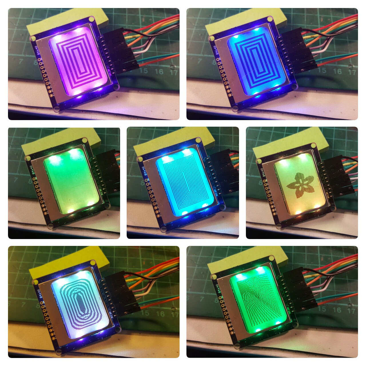
Notes:
- definitely order 0.8mm boards (I failed because it was after midnight... )
- pins for display can be shortened by shield -> edit footprint!
- 5V stuff is confusing! I only considered it for getting more "bang" for the buck
- next version should have Attiny13 for I2C RGB control
- maybe add an ESP12 foot print
- play with MQTT (red alert / temperature stuff)
- also RGB pinout is not correct!
- resistors for colors are not in the same order and values must be corrected
- ESP12 analogWrite has 10bit resolution!

 davedarko
Discussions
Become a Hackaday.io Member
Create an account to leave a comment. Already have an account? Log In.
Nice!
Are you sure? yes | no
It's pretty bad when your buck converters give you bang.
Are you sure? yes | no
yeah, but when you forget that for 3V3 you have to connect some pads first to make it work ... then I really don't see the point in it at all. If some people still uses 5V boards than they should buy some cheap converters on eBay or something :)
Are you sure? yes | no
That backlighting is pretty slick. Did you use regular smt LEDs or did they have to be right-angle?
Are you sure? yes | no
regular 0603 / 0606 smd rgb leds, I think they mostly reflect on the metal case, they shoot straight up into the plastic, but it looks even better in real life :)
Are you sure? yes | no