 John Anderson
For the second iteration of the Digital Dice Tower, I decided to add some sound. At first, I was simply going to add some beeps and boops to make the die rolling a little more interesting. But, then I decided to take it to the next level with sampled PCM sound of dice rolling in one my "analog" dice towers. Once I got that working, I decided to challenge myself to make it talk. After all, how hard could that be?
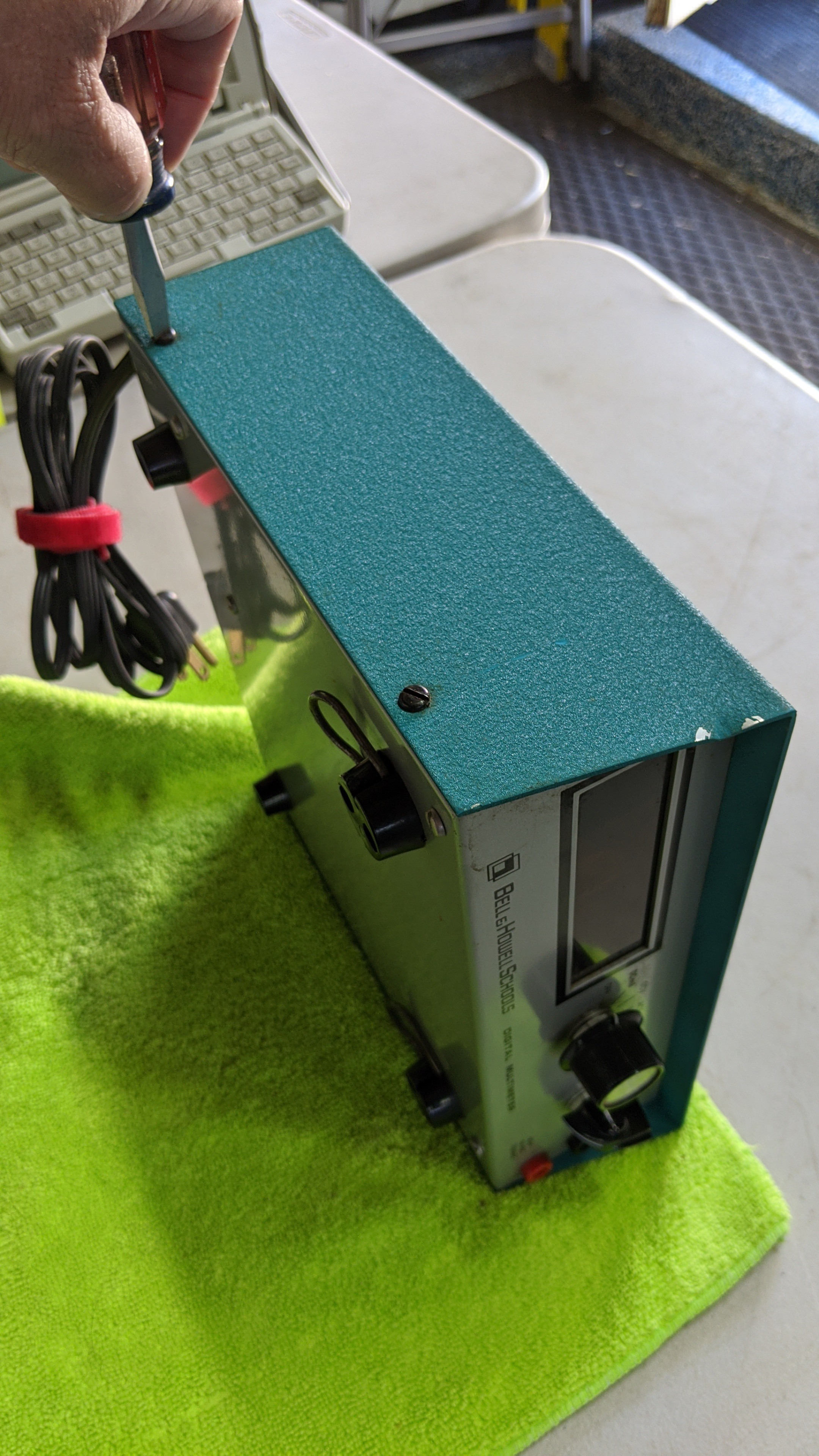
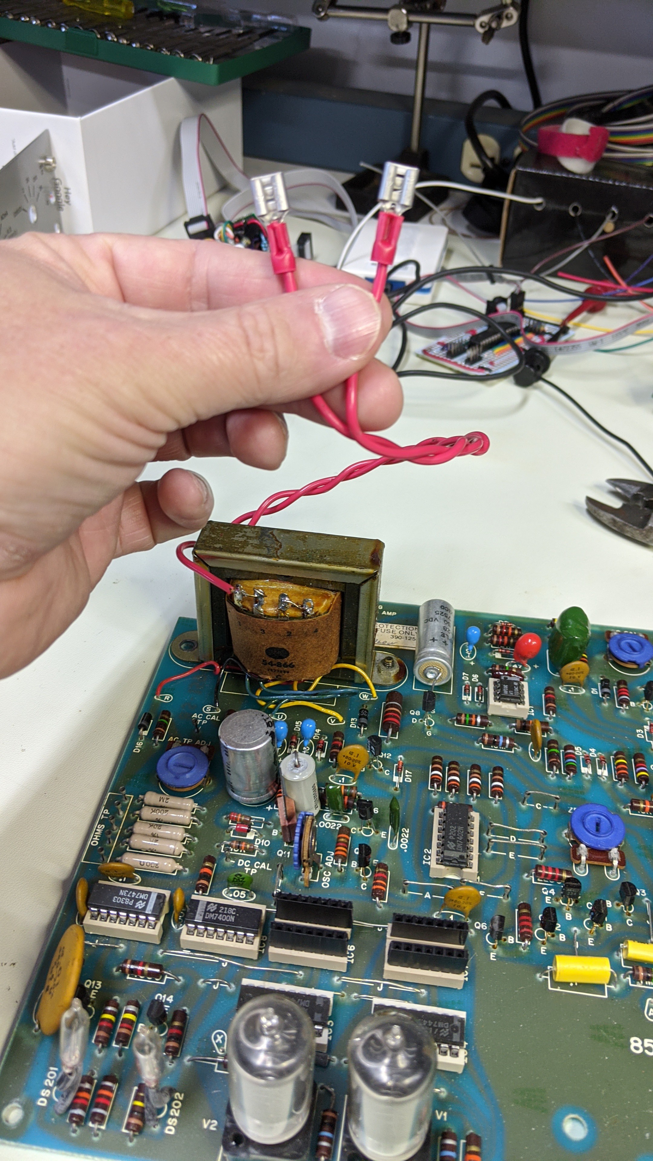
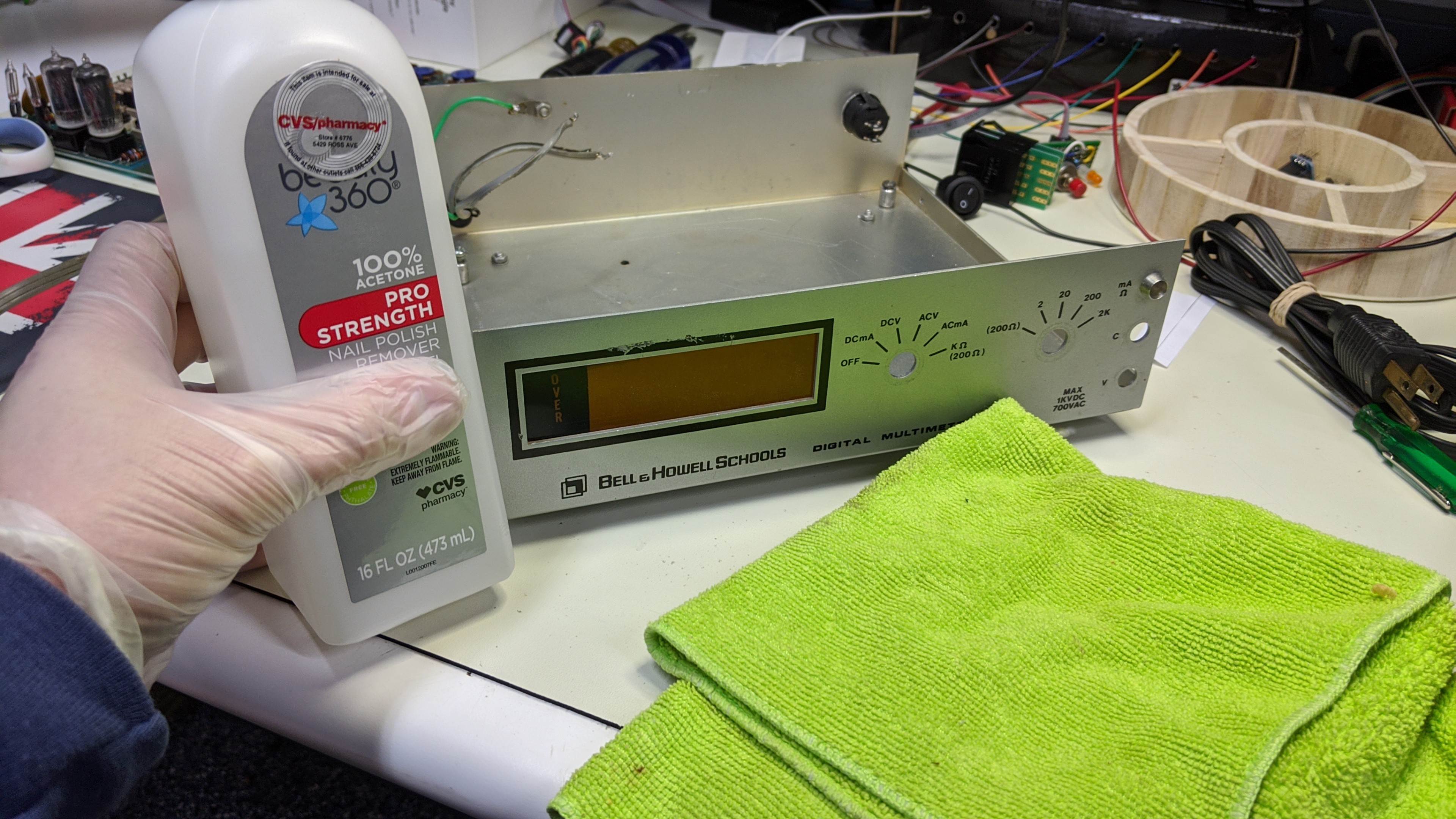
Before I could worry about making sounds, I needed to build the next piece. Again, I decided to "recycle" a Bell & Howell IMD-202-2 Multi-meter.
Gut it and Prep it...
Step 1, open the case.
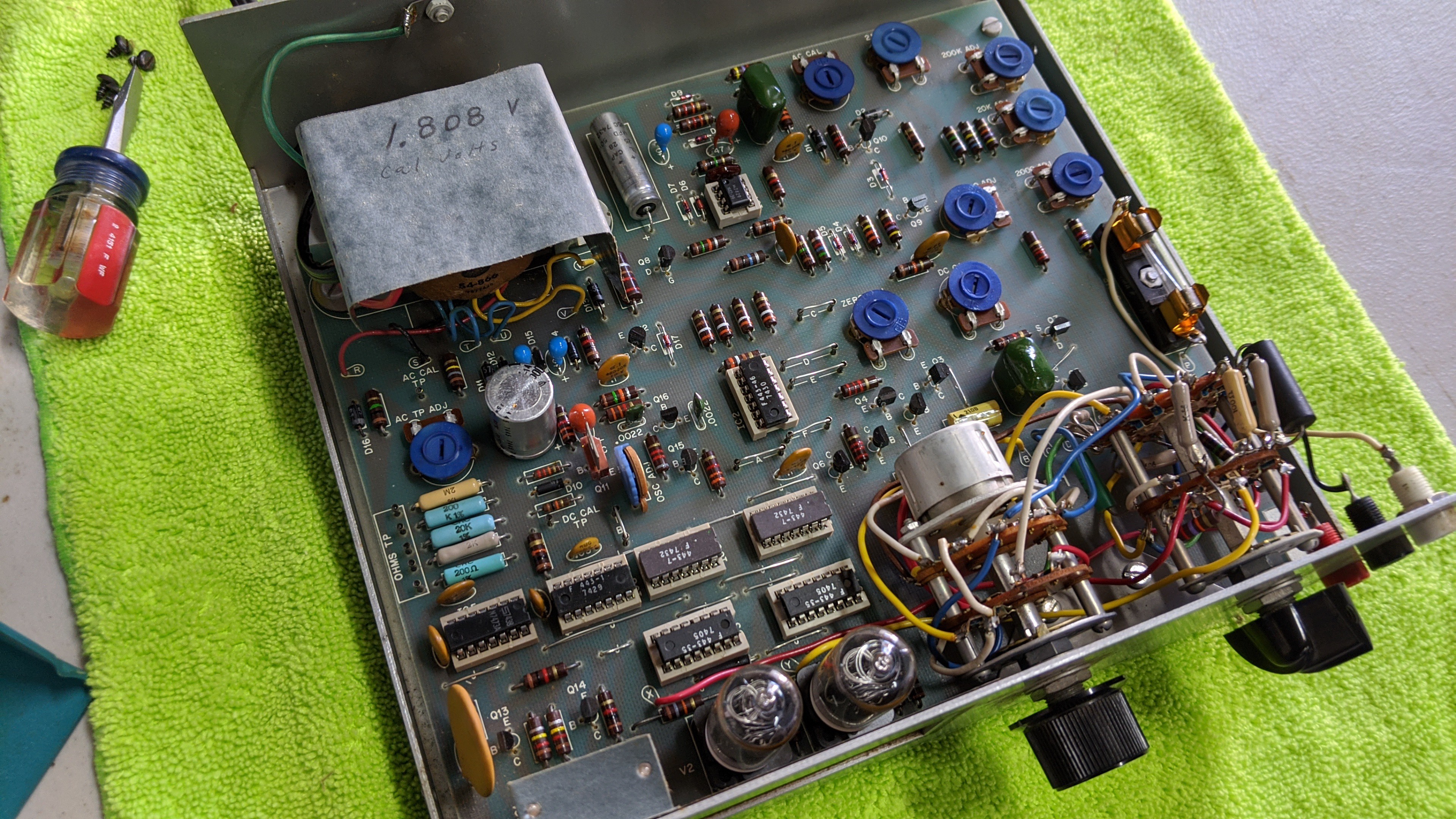
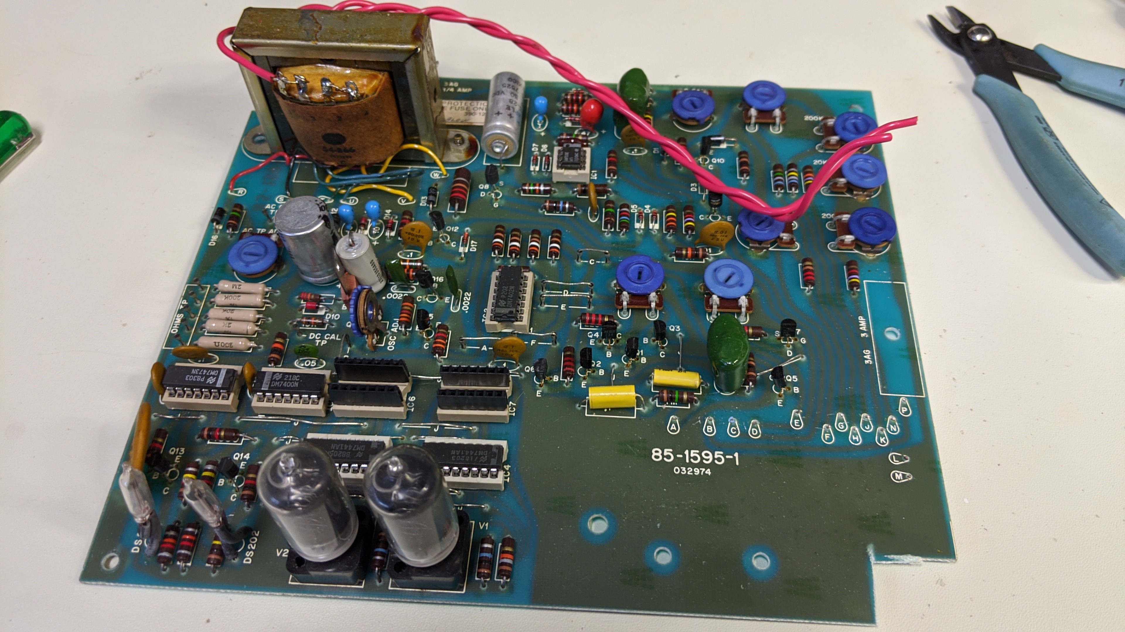
Remove the switches and PCB. Note: I notched the PCB to make room for the speaker, button, LED daughter board.
Install a rocker switch in the rear of the case for power on/off.
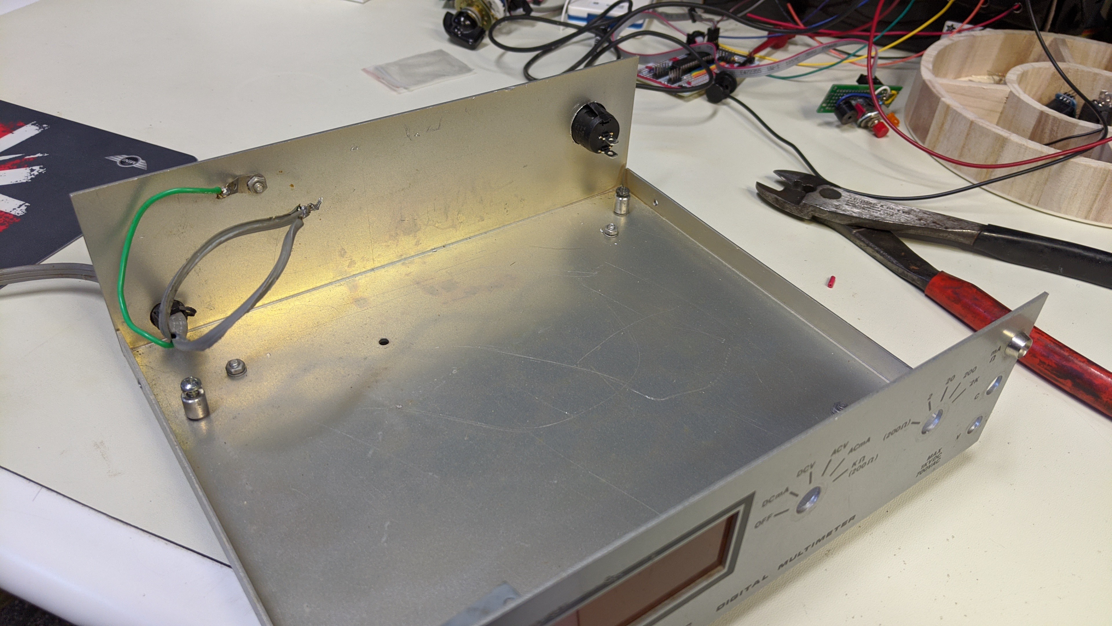
Wire up the transformer to the new power rocker switch.
We Have Assumed Control...
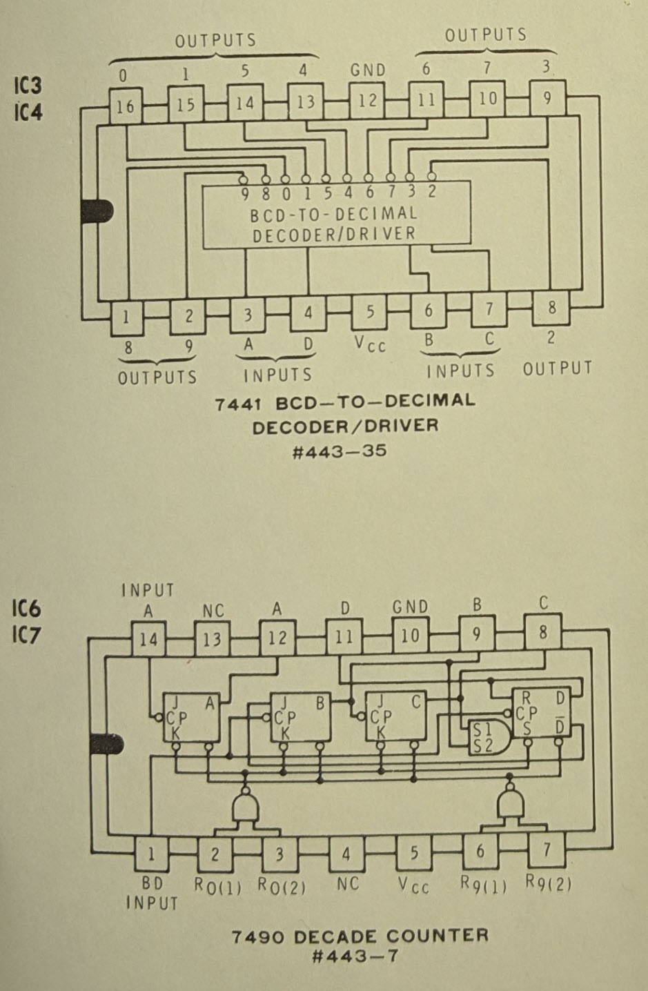
The next step is to build the controller board and interface it with the original PCB with power supply, 7441 decoders/drivers, and nixie tubes.
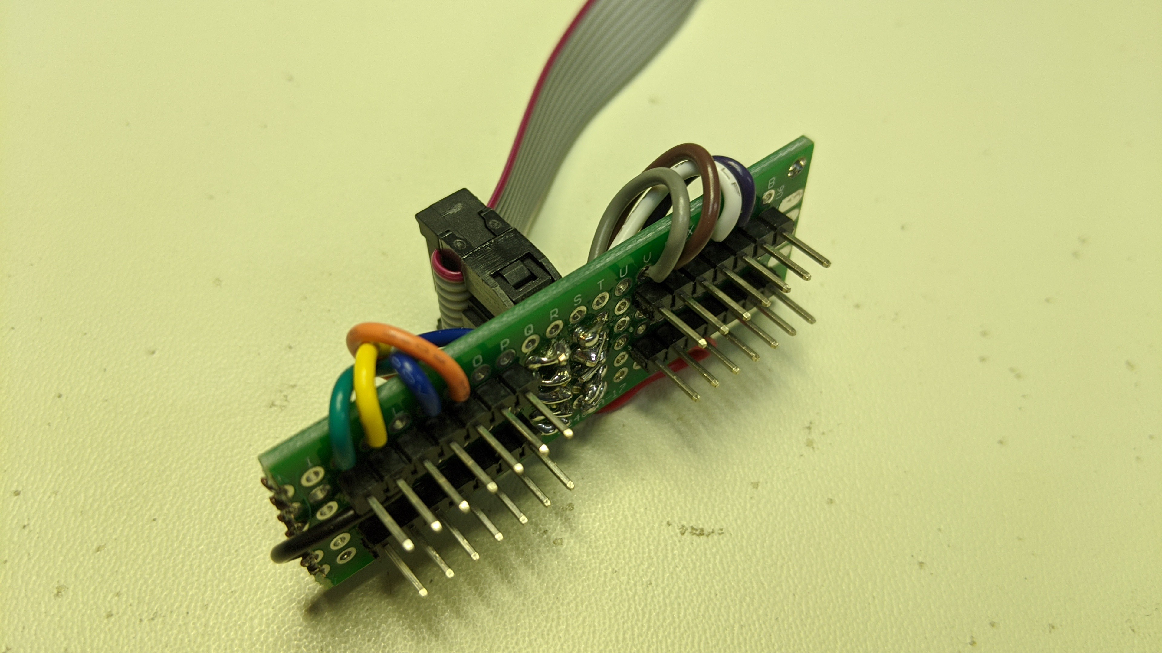
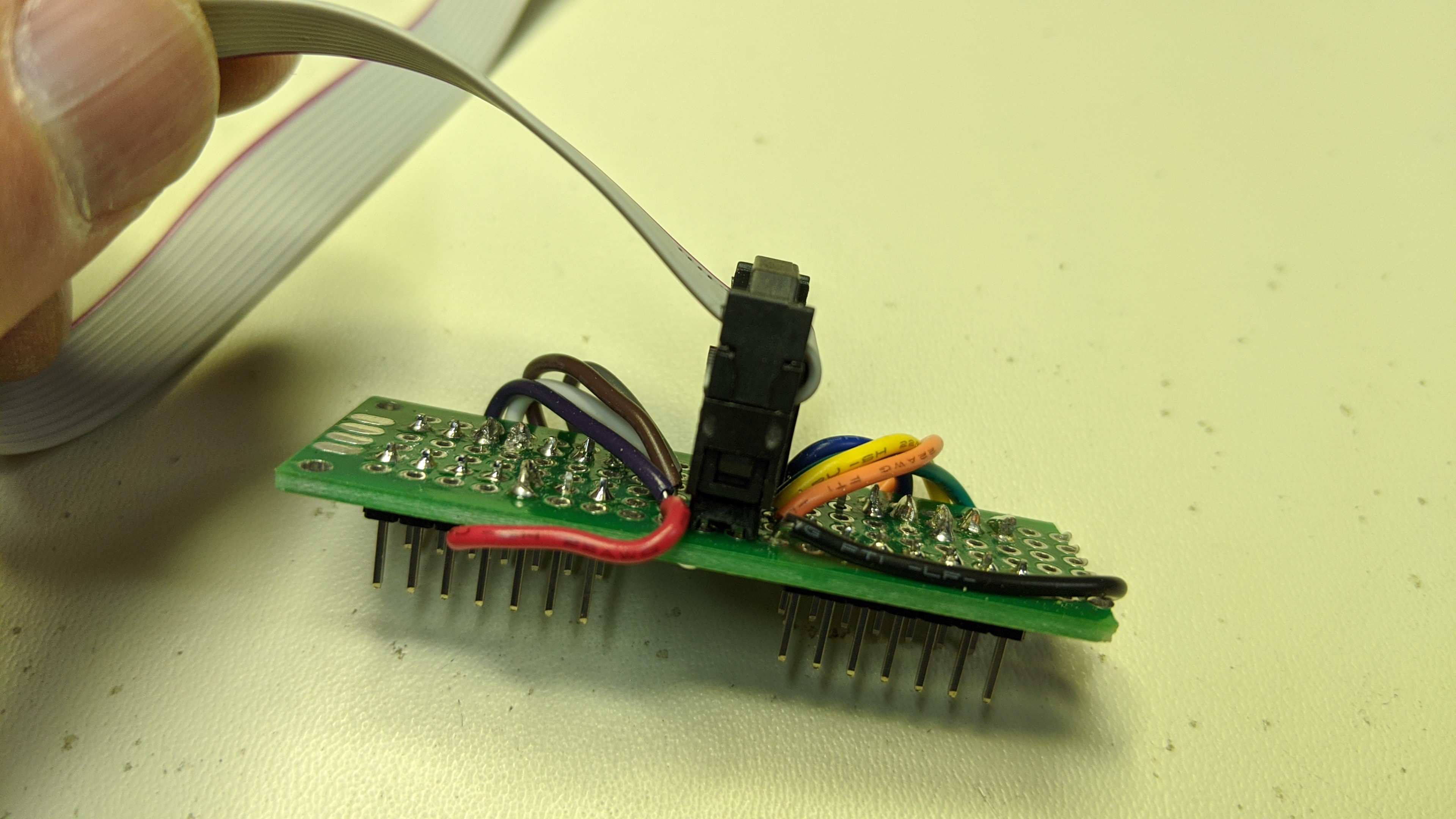
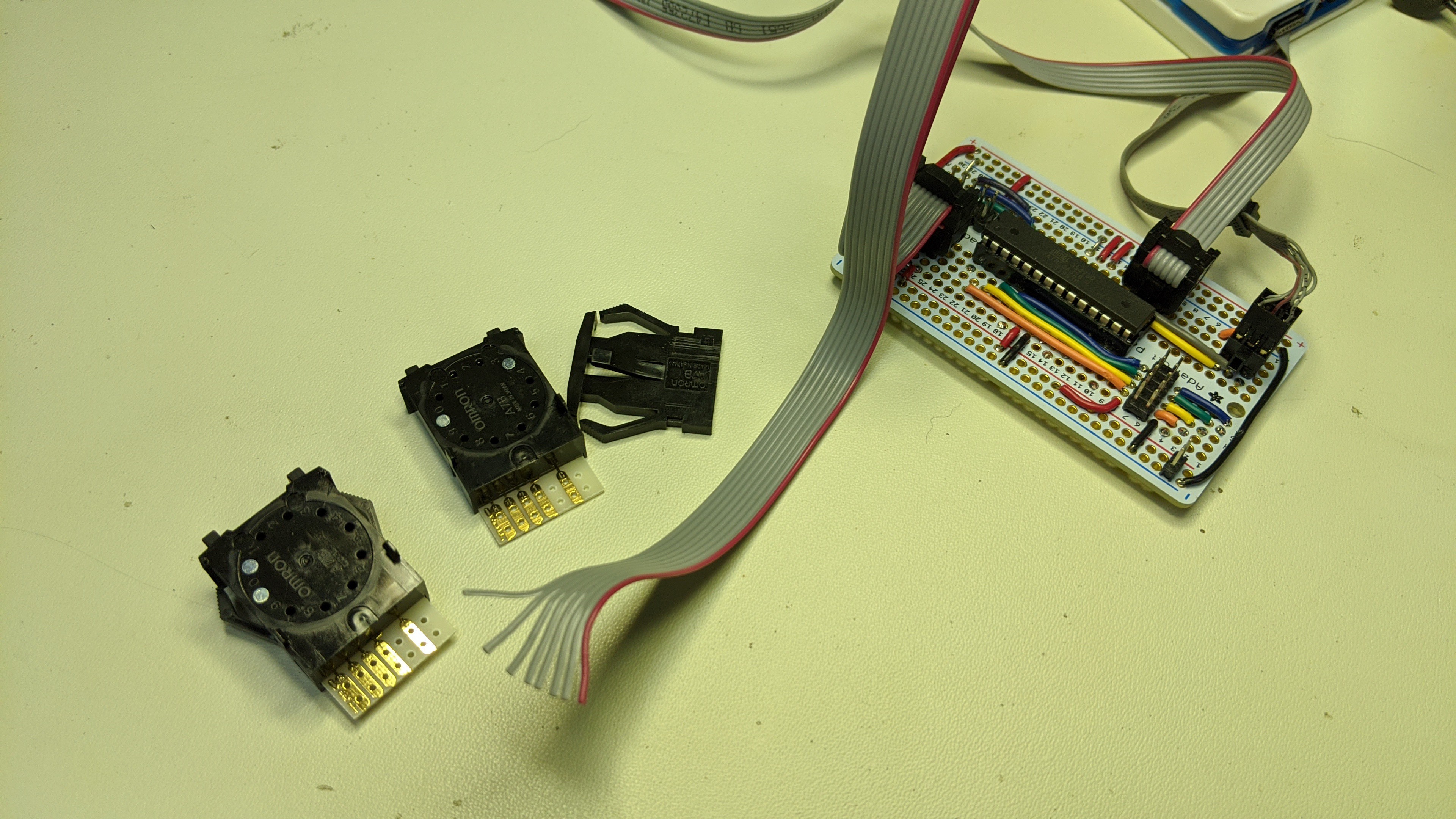
I started with the interface to the PCB. I wired up the a small piece of protoboard with four 7 pin single row headers and a 10 pin dual row header. The single row headers line up with the 7490 decode counter sockets in the original PCB. To make that work, I pressed the single row headers into the sockets and then put the protoboard onto the headers. I soldered the headers to the protoboard there in place. This ensured they line up perfectly. Then I wired up the Vcc, Gnd, Output A, Output B, Output C, and Output D to the 10 pin connector.
For more details and schematics regarding the original PCB, checkout these logs from the original project: Let there be light... and Getting Started...
The protoboard that interfaces to the original PCB looked like this when I was done.
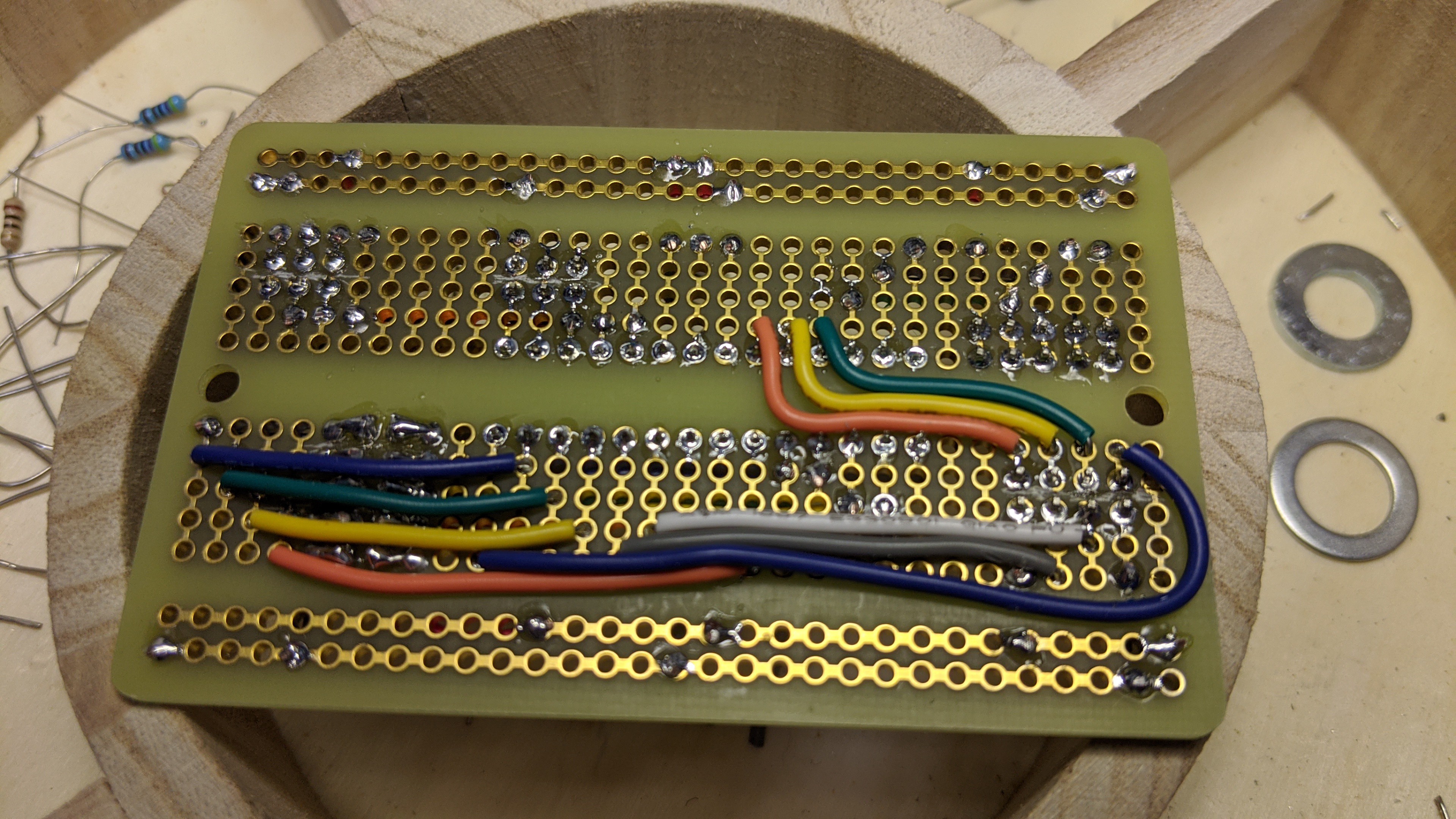
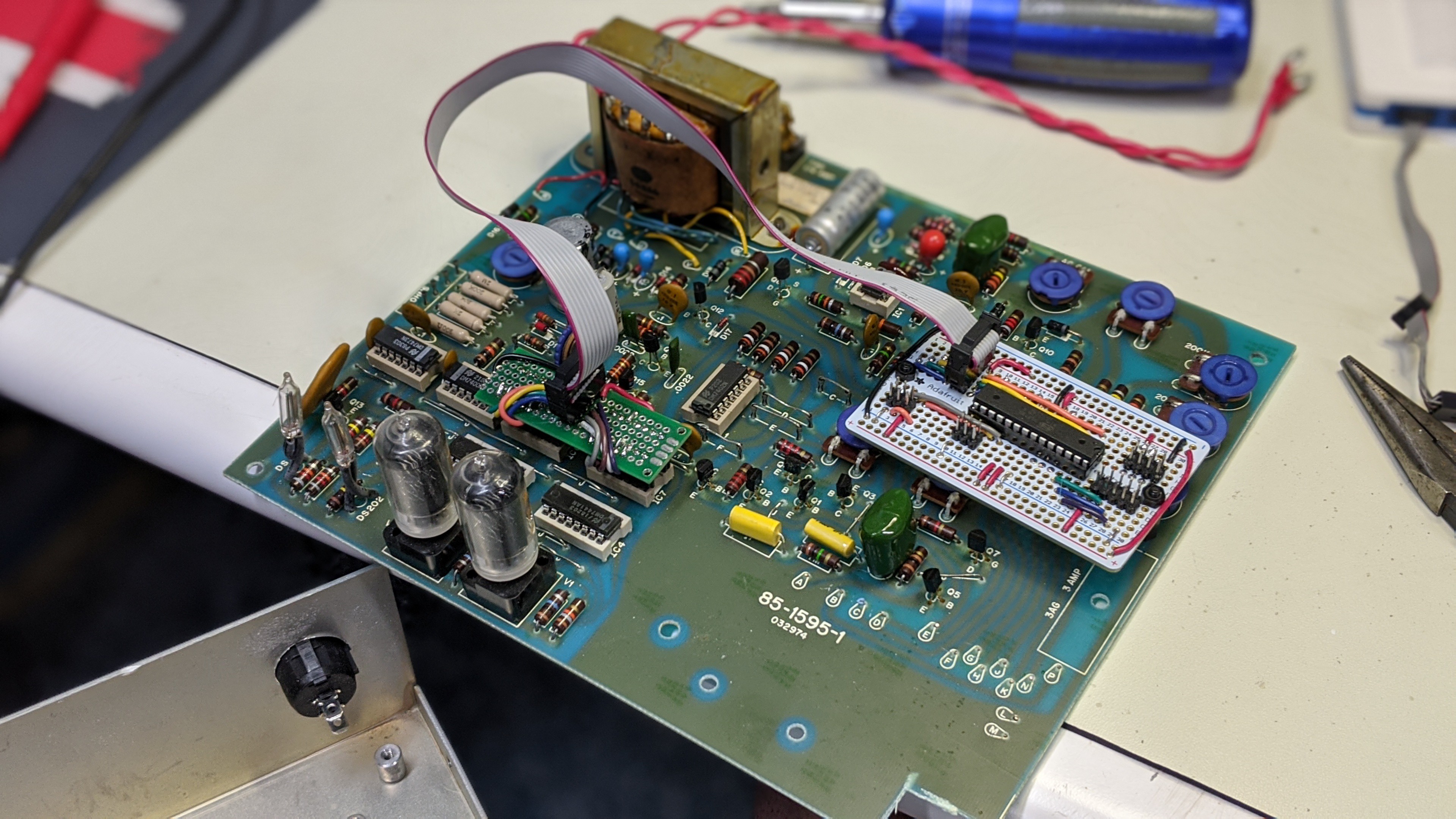
Next, I wired up the controller board. It contains the ATmeg328 microcontroller and connectors to the original PCB, thumbwheel switch, rotary switch, LED/push button/speaker daughter board, and ISP programming/debug port. I am using the integrated oscillator so once again the controller board is just the controller, wires, and connectors.
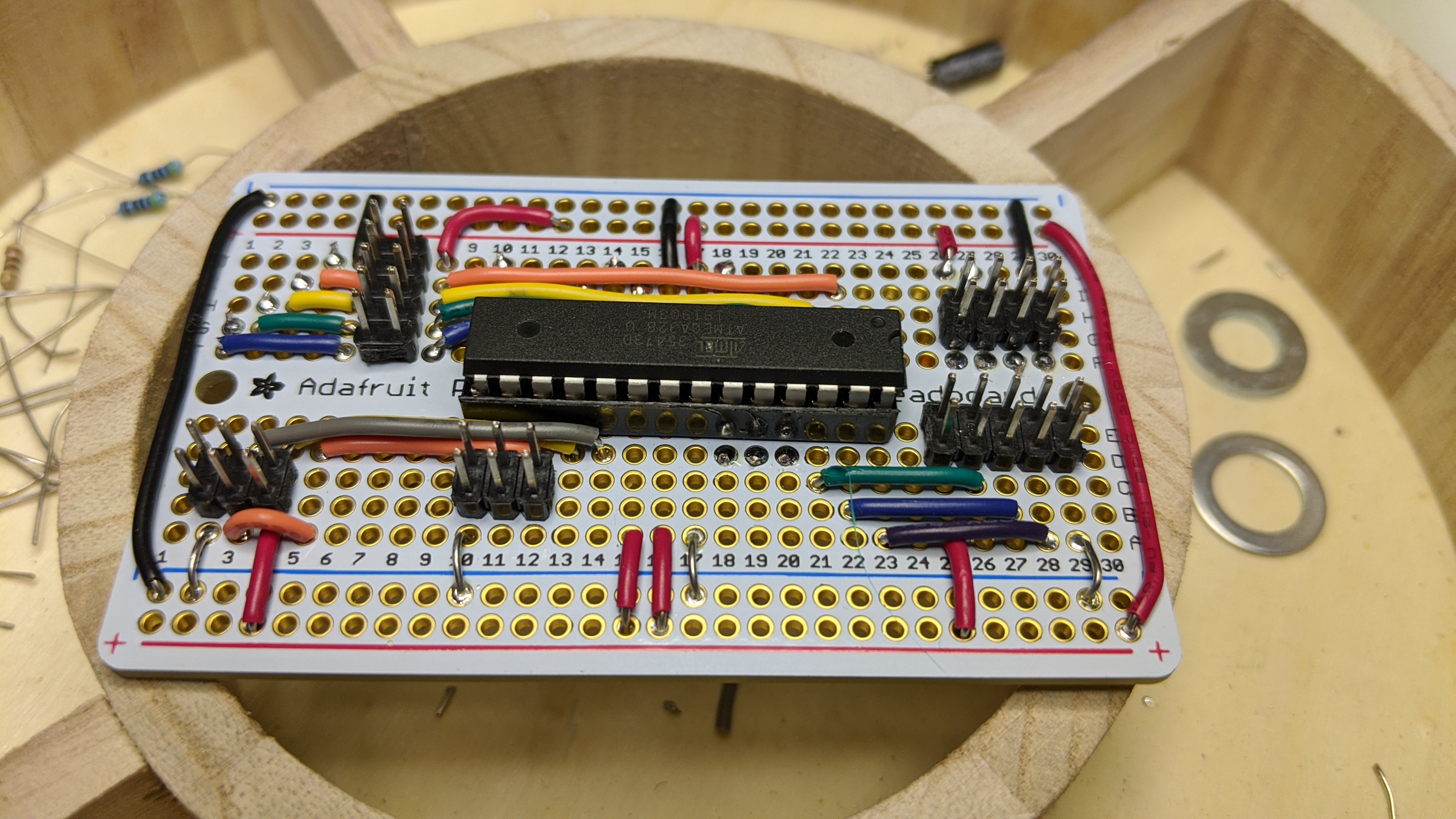
Note: If you look closely, you can see where I cut traces on the protoboard so I could used the dual row connectors. I've seen some breadboard style protoboards lately that have the traces on both sides under a solder mask. Don't buy those. I really like these Adafruit protoboards because they use thin traces that are easy to cut and the holes are plated through.
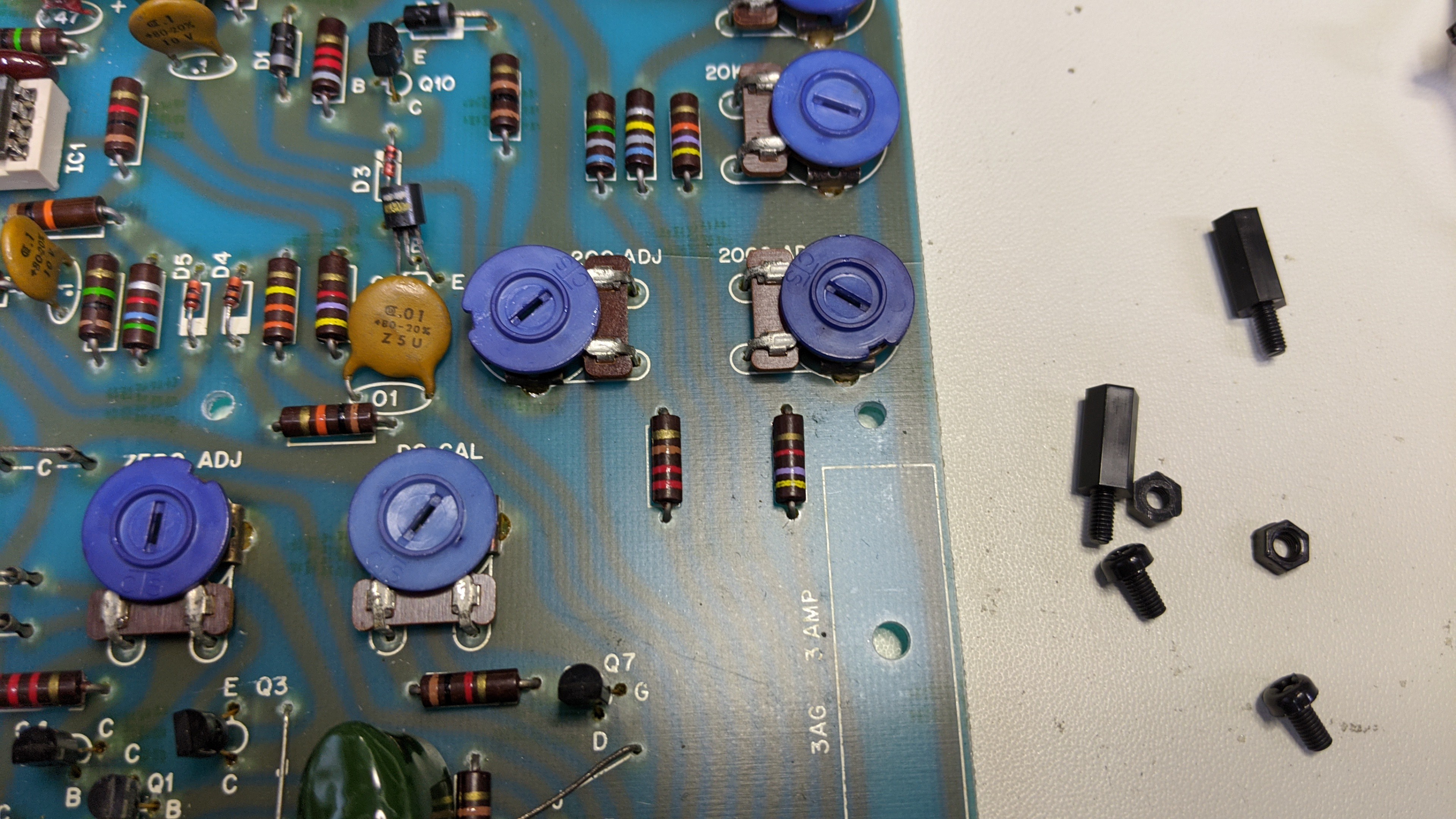
Lastly, I selected a location on the original PCB to mount the controller board. I picked a spot on the right side of the board behind the switched where I could drill without cutting existing traces.
Installed the standoffs.
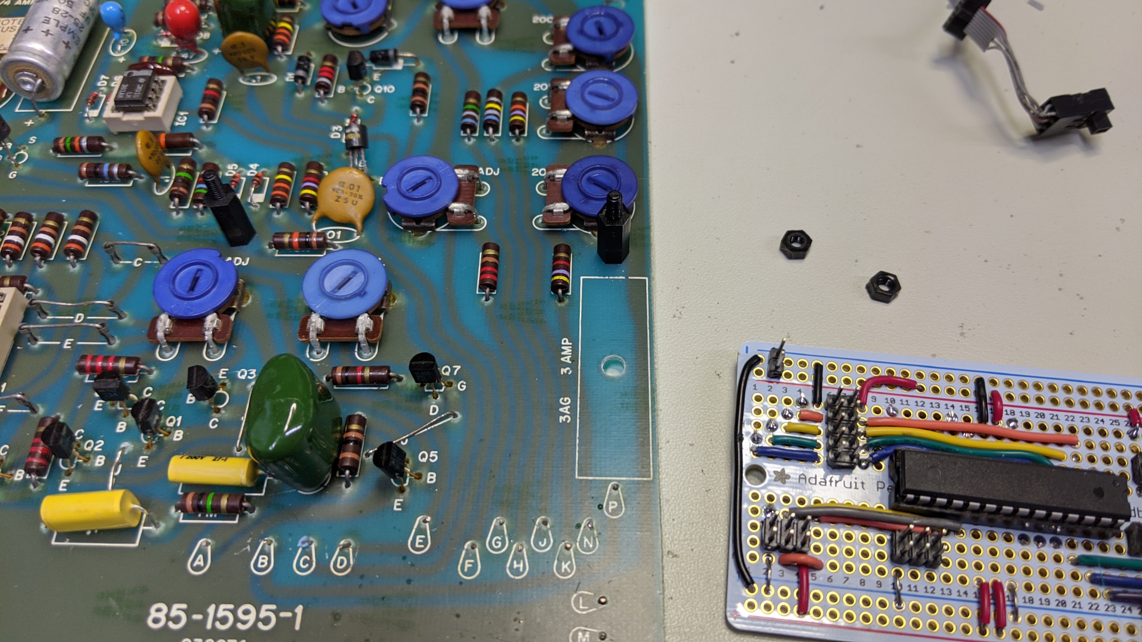
And, installed the controller board.
Mod the Case...
Now that I had the control board built and connected to the original PCB, I needed to modify the case so the new switches can be installed. As mentioned before, I tried to simplify the modifications to the front faceplate this time. Instead of cutting a larger hole in the original faceplate and riveting a new faceplate over it, I decided to modify the original faceplate to install square thumbwheel switch and use existing holes in the faceplate for the rotary switch, LED, push-button, and speaker hole.
The first task was cleaning the old graphics off the original faceplate. I used some 100% acetone and rag to do that.
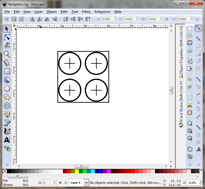
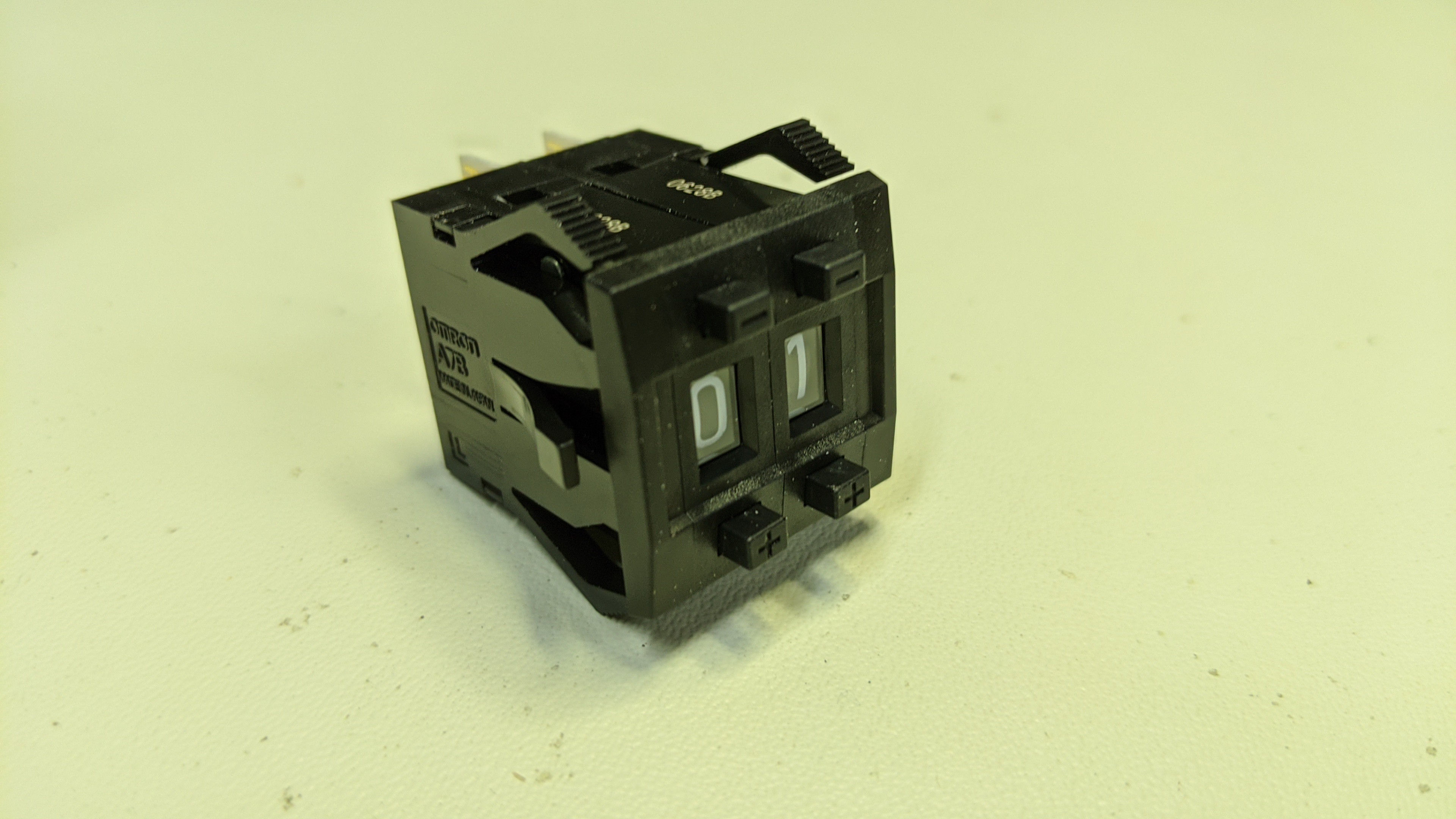
Then I drew up a template for the 22.5 mm x 22.5 mm square hole required for the 2 Digit Omron A7BS BCD encoded thumbwheel switch and end caps. I used Inkscape to draw it to scale and printed it.
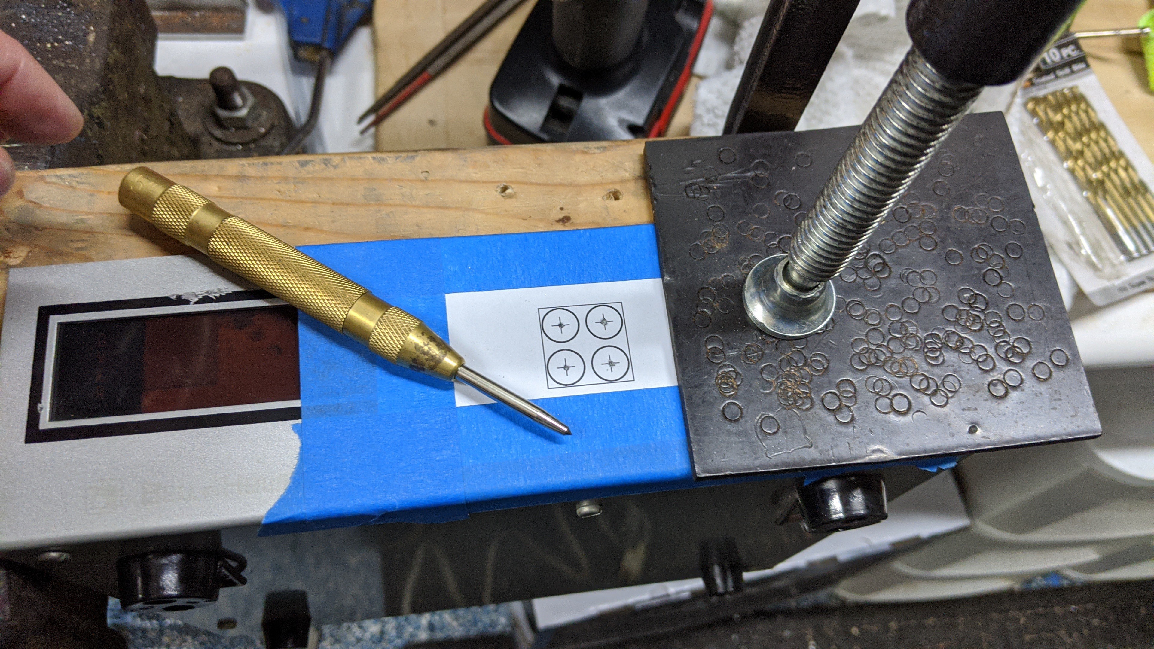
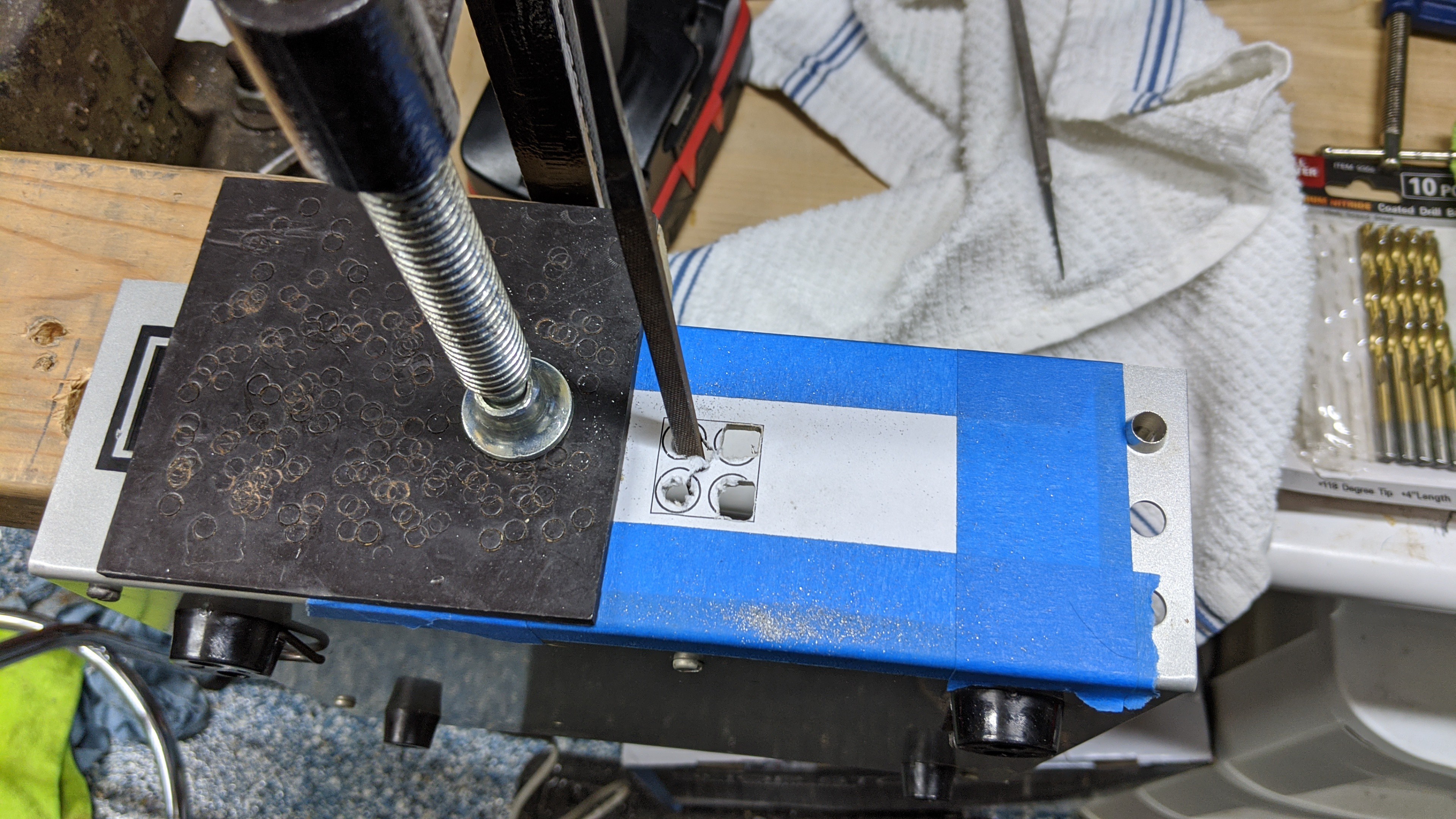
I then taped this paper template to the front faceplate of the case and secured it to a scrap piece of 2x4. I was generous with the template and painters tape used to secure it. This provides a protective barrier the prevents scratches on the faceplate while drilling, filing, cutting, etc.. Once secured in the vise, I punched the center point of the marked drill holes in the template.
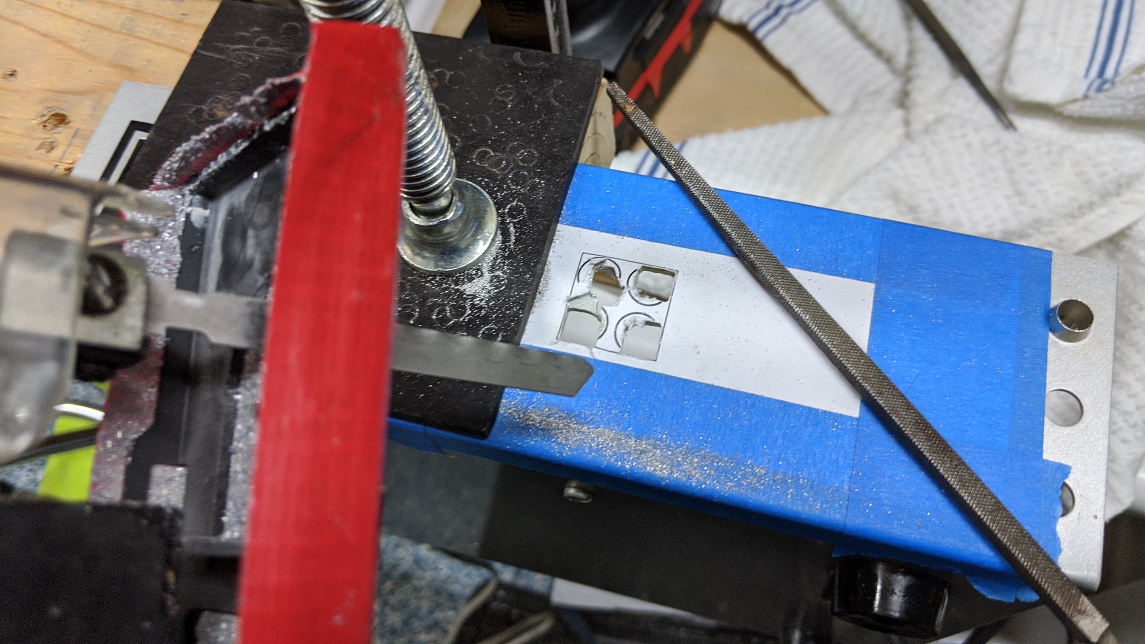
Next I drilled the holes and used a square file to start squaring off the corners marked by the template. I had to be a little careful to keep everything inside the lines of the template. The aluminum sheet metal files very easily.
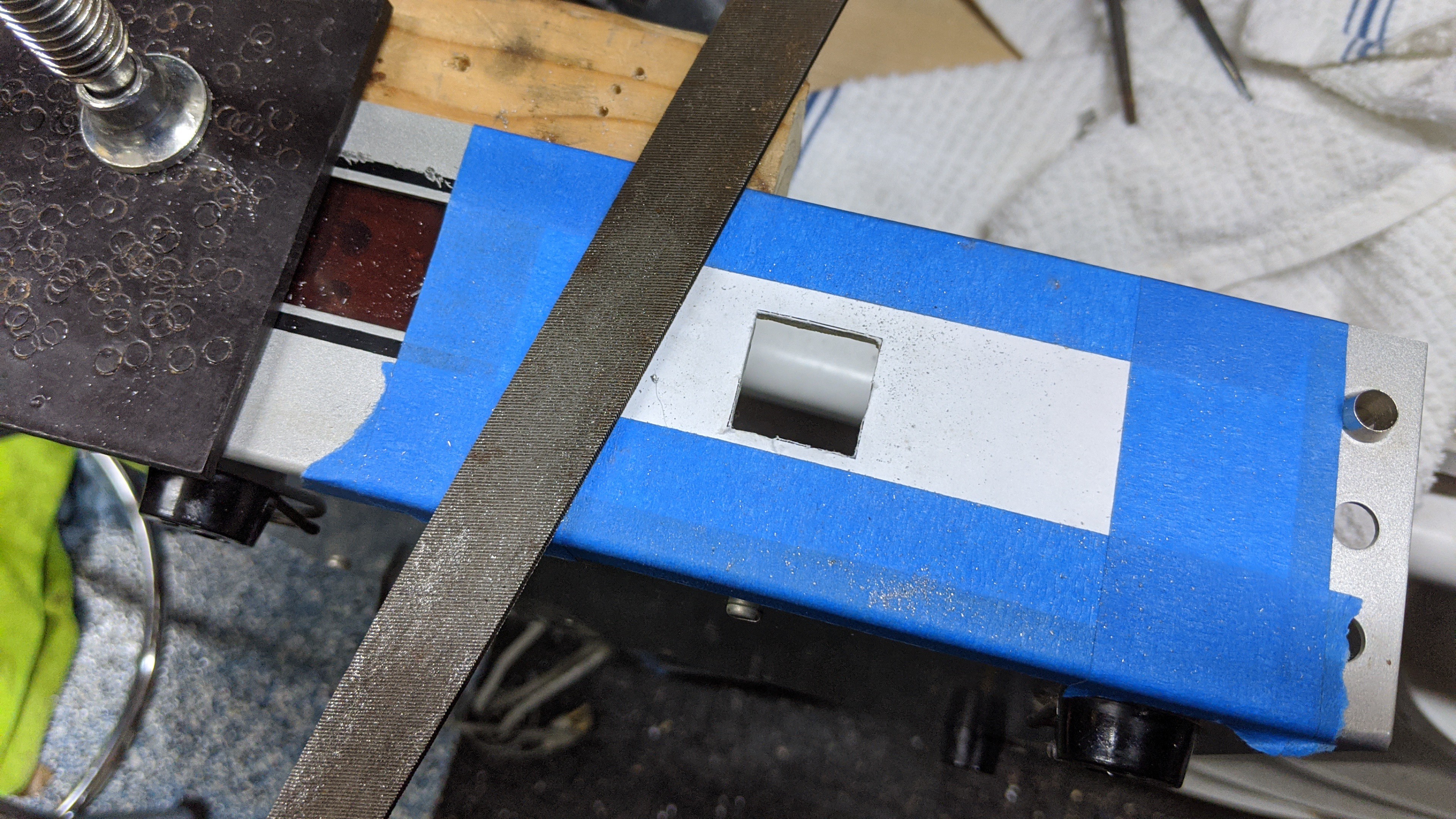
Once three of the four holes were squared to the corners of the template square, I used a jigsaw to cut out each side of the square. The filed holes were just large enough to fit the jigsaw blade flush to each side of the square. Again, I had to be very careful to cut slowly following the template line and not cutting past the perpendicular line of the next side.
With the cuts complete and the remaining bit of metal removed, I used a larger metal file to clean up the square a little. I then test fitted the thumbwheel switch and filed a little more until it slid in snugly. My template was intentionally about .2 mm too small so I wouldn't end up with a hole too large. I knew filing the last .1 - .2 mm would be more precise than cutting. It was easy to file and took just a couple minutes to get it just right.
Once I was satisfied with the fit, I pulled off the tape and template paper.
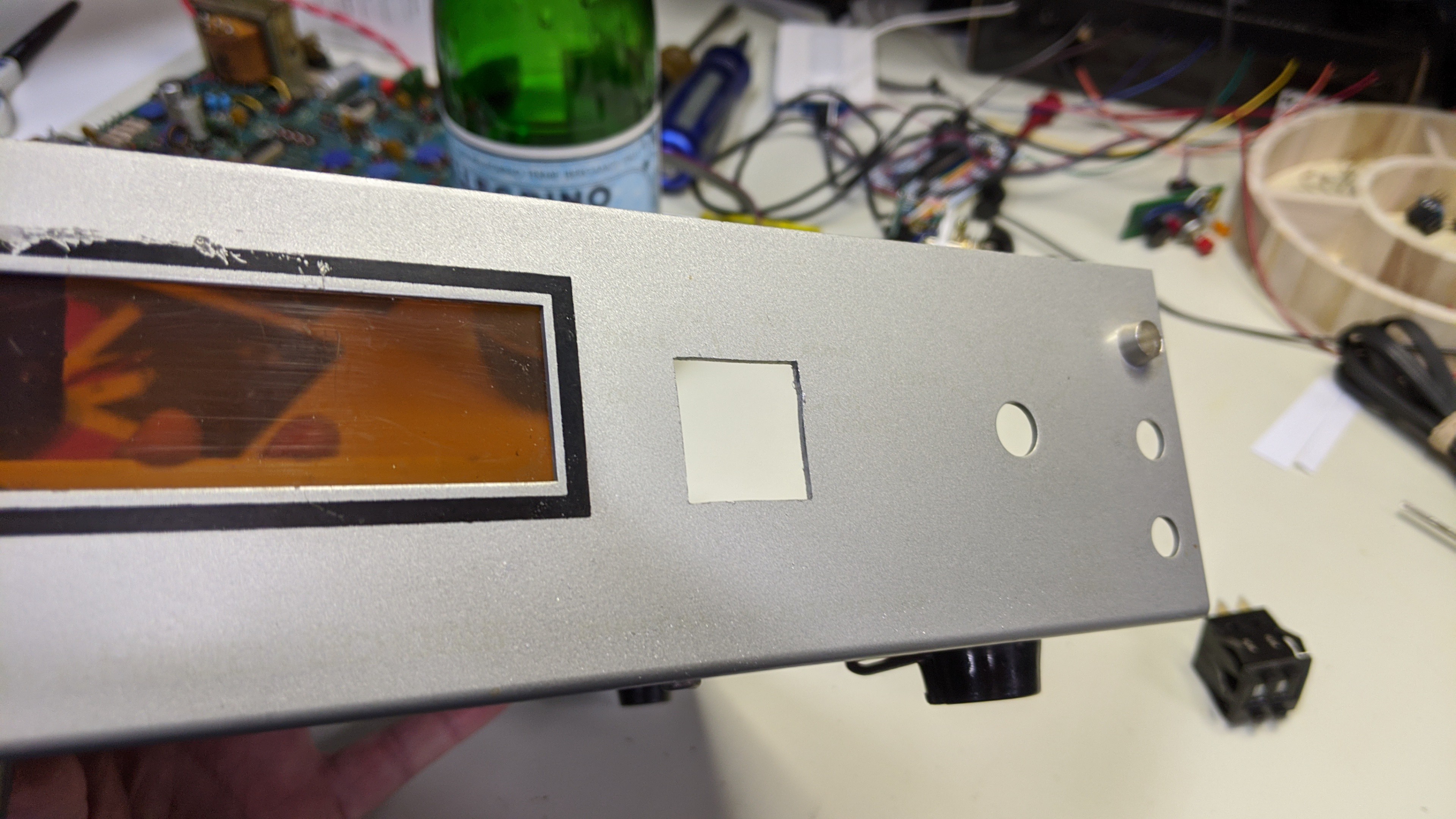
And, the fit for the switch looked like this. BTW, don't press the switch into place just yet. Once it snaps into place it's difficult to remove. I still needed to configure and solder the cable to the switch.
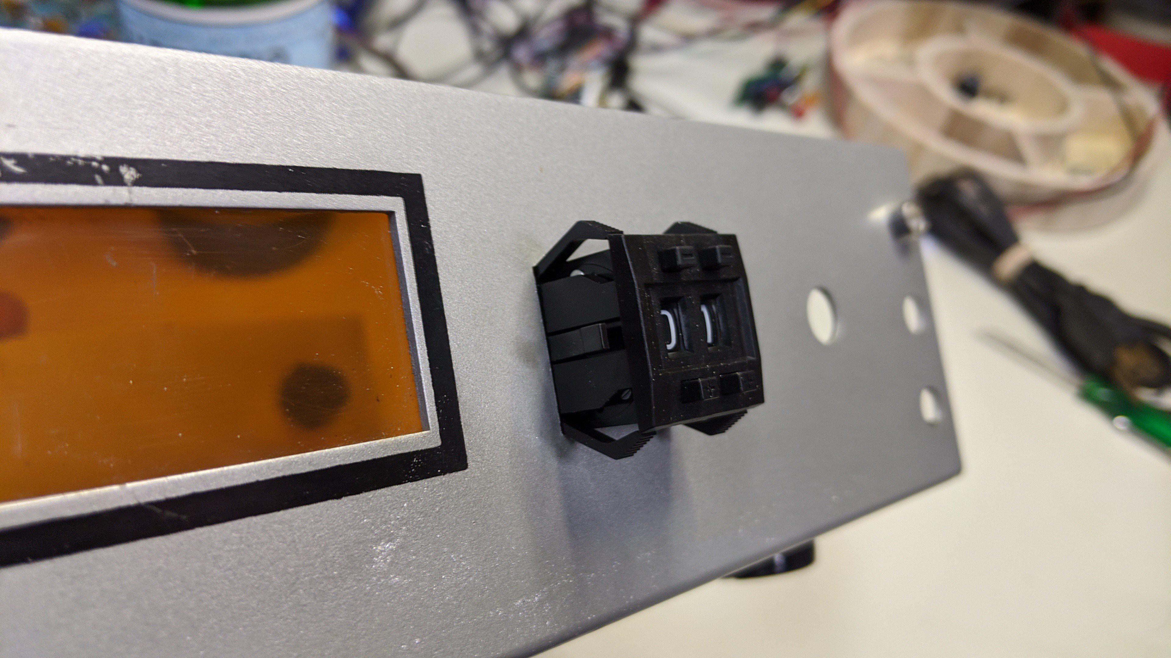
The rest of the holes will be used as is. In the pics above, you can see that I also test fitted the panel mount LED holder as well.
User Interface Circa 1978
The next step was to configure/build the new user interface switches, button, and speaker and wire those to the controller board.
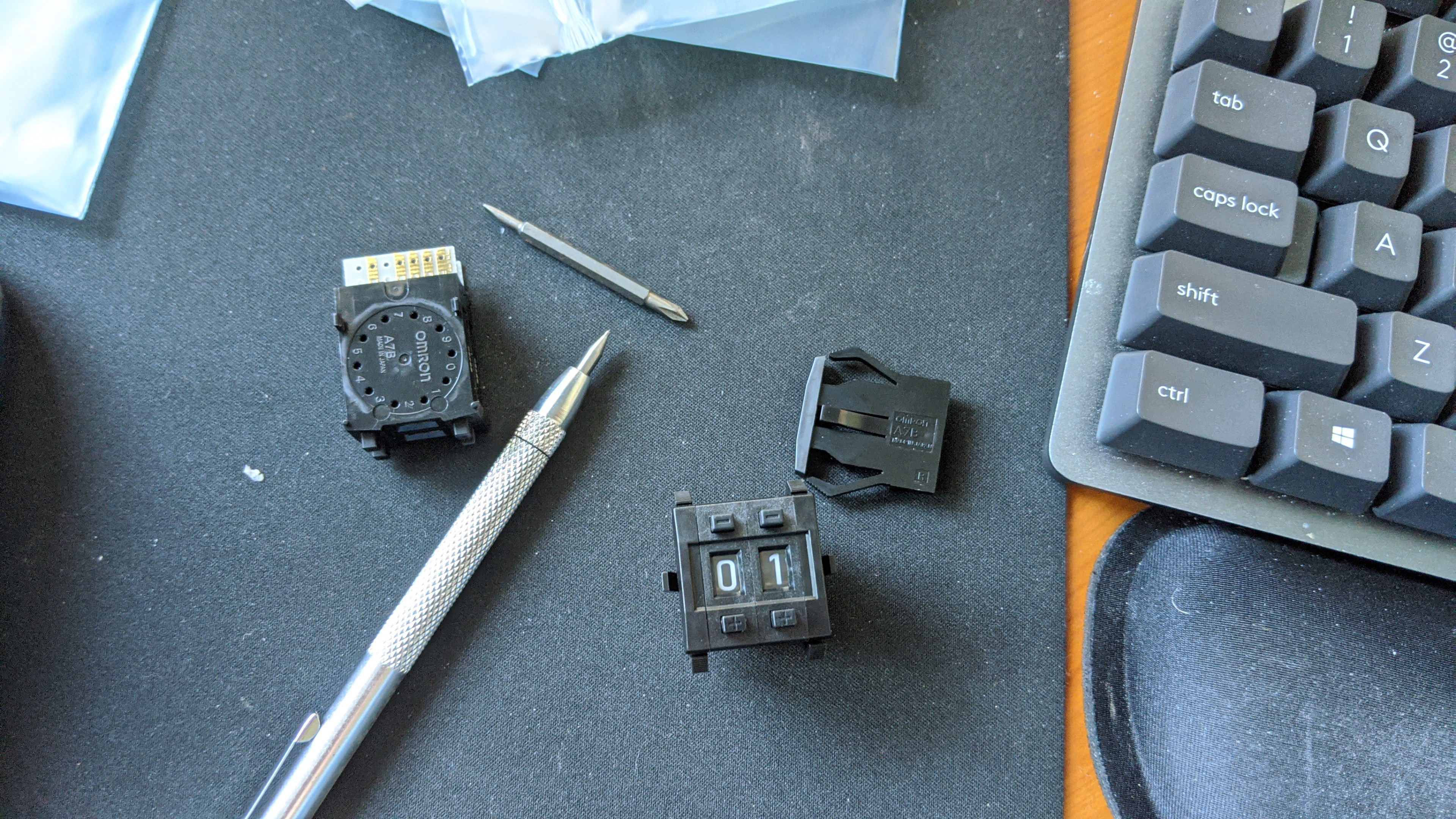
The two digit Omron Thumbwheel is configurable. It comes with pins that you install. This pins act as stops preventing the user from selecting a range of numbers. This is useful because I could reduce the range of selectable dice counts down to something realistic and reduce the number input pins required on the microcontroller. So, I installed the stops making the selectable tens digit range 0-3. This makes the user selectable range for the number of dice 0-39 and reduces the pins required for the dice count input from 8 to 6.
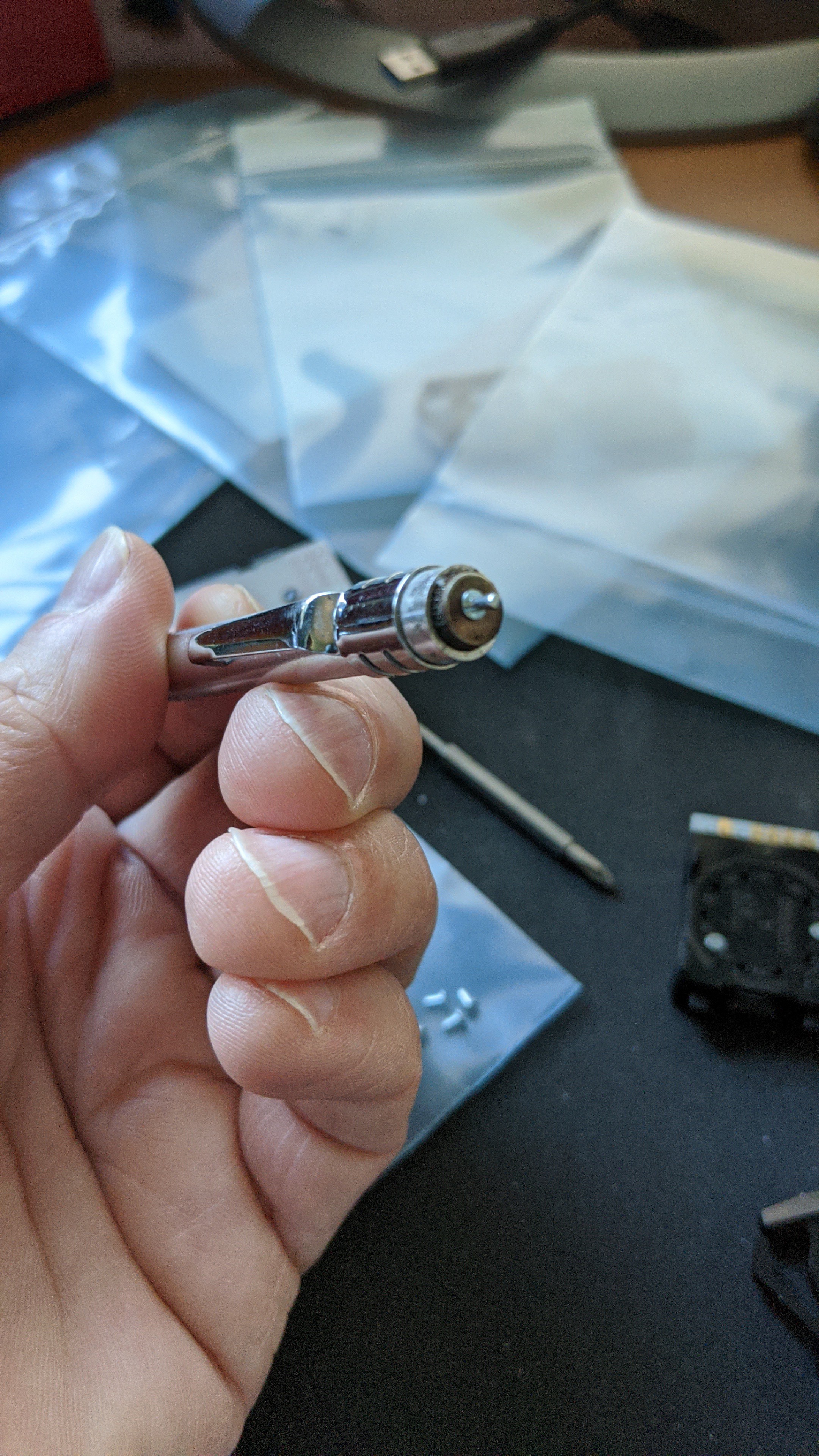
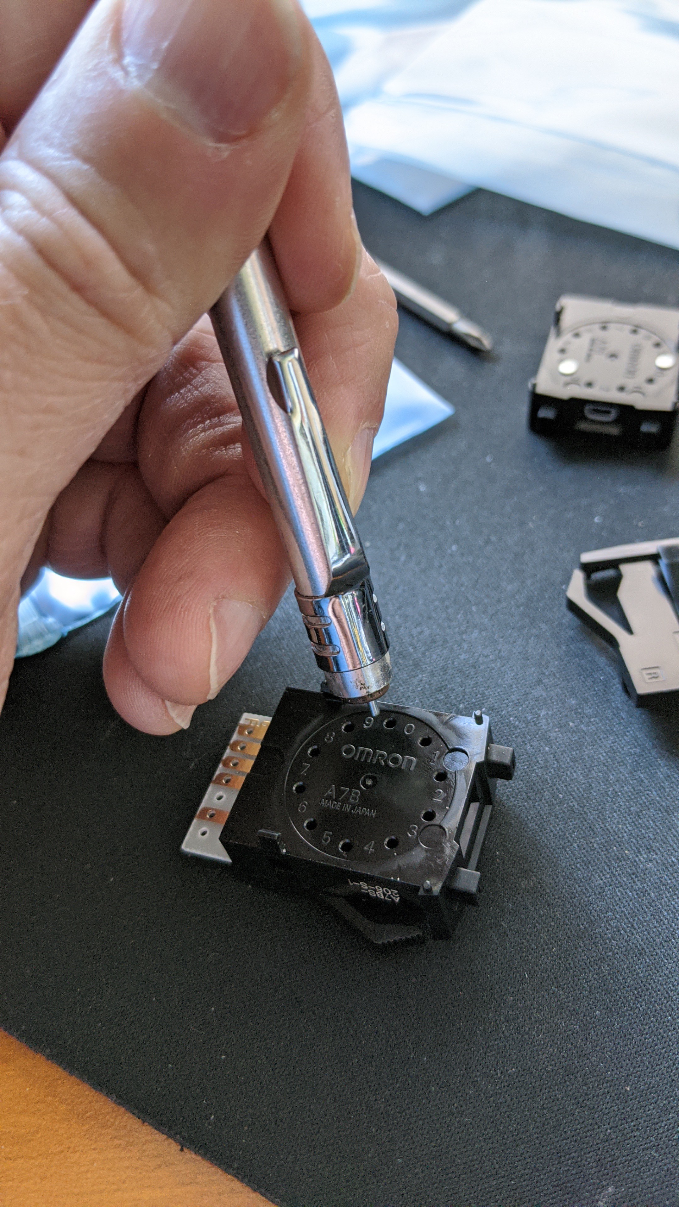
The pins that came with the switch are rather small and difficult to handle with my fingers. But, they are made of a ferrous metal. I discovered that I could used the magnetic end of my scribe tool to hold the pins and install them.
With those in place, the two digits snap together and the end caps snap onto each side of those.
After the thumbwheel was all configured, it was a simple matter of soldering a 10 pin cable to the 4 BCD traces of the ones digit, the common on the ones digit, the 2 low order BCD traces of the tens digit, and the common on the tens digit.
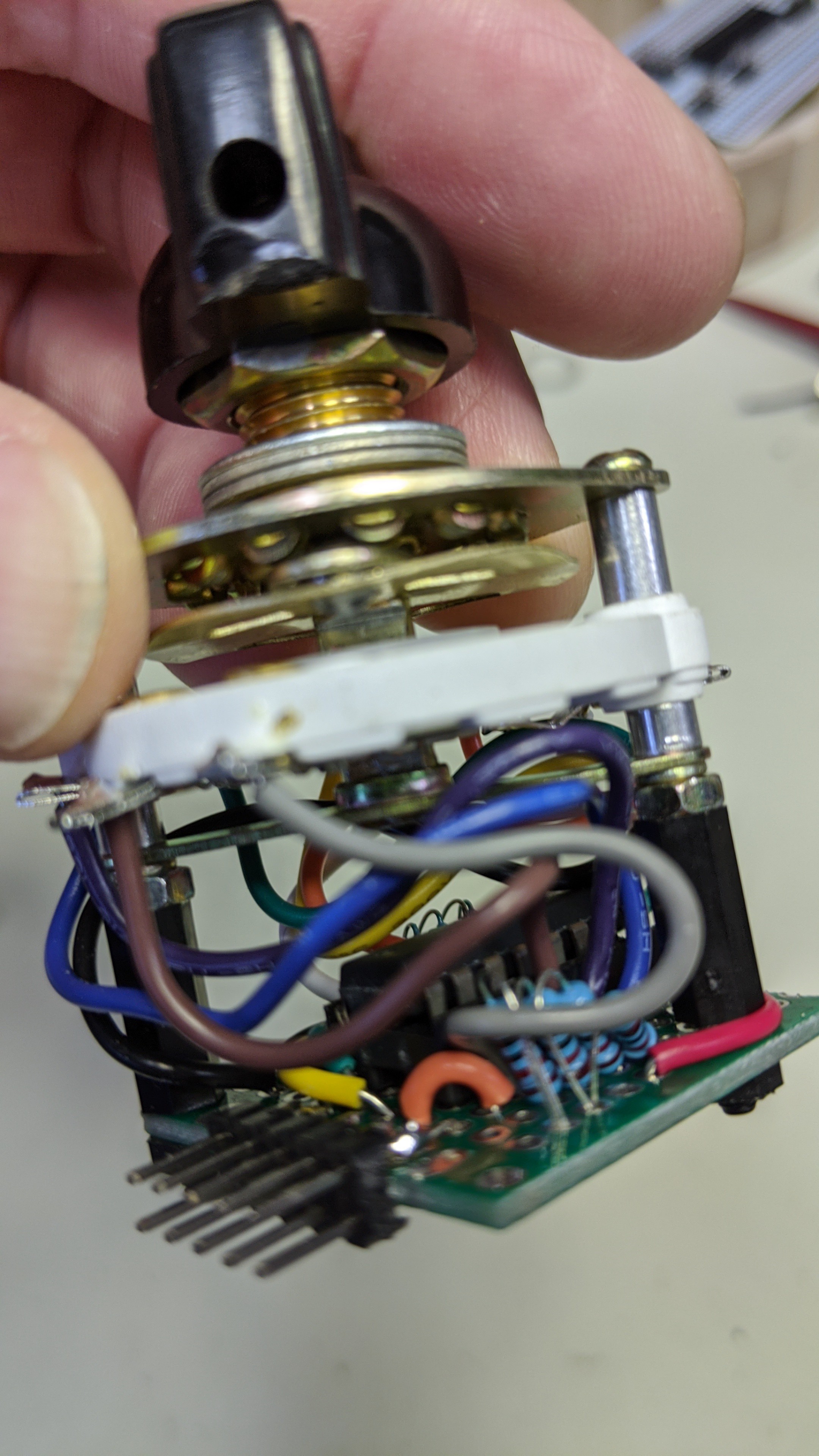
The rotary switch required a little more effort to wire up. Just like the previous version of the dice tower, I used a simple single pole 8 way rotary switch. However, I wanted to minimize the cable conductors and controller input pins required. So, I wired up a 74HC148 8 line to 3 line priority encoder on a small proto-board.
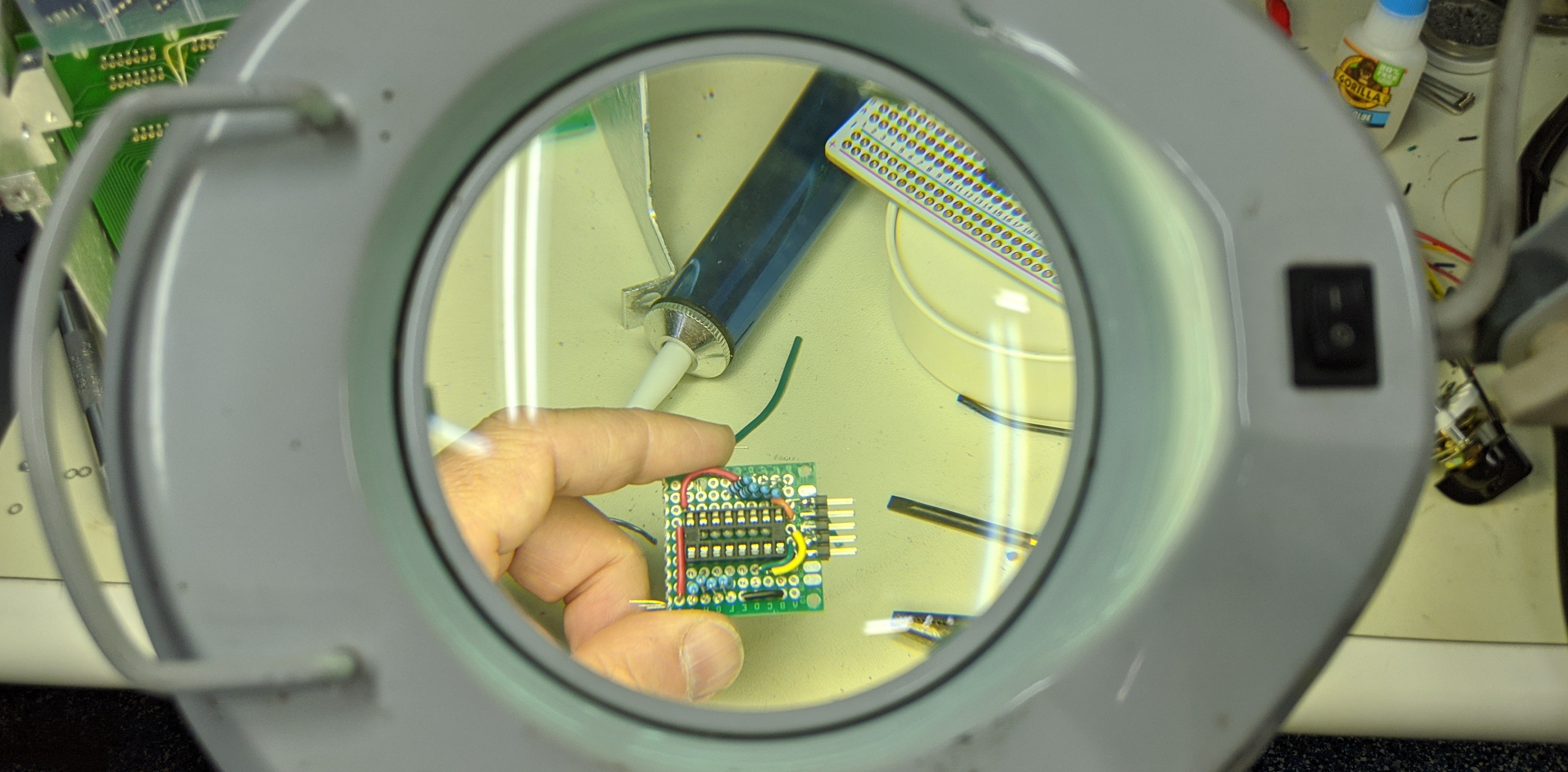
I then wired the board to the common and 8 selector lugs and used a couple stand-offs to connect it to the back of the switch.
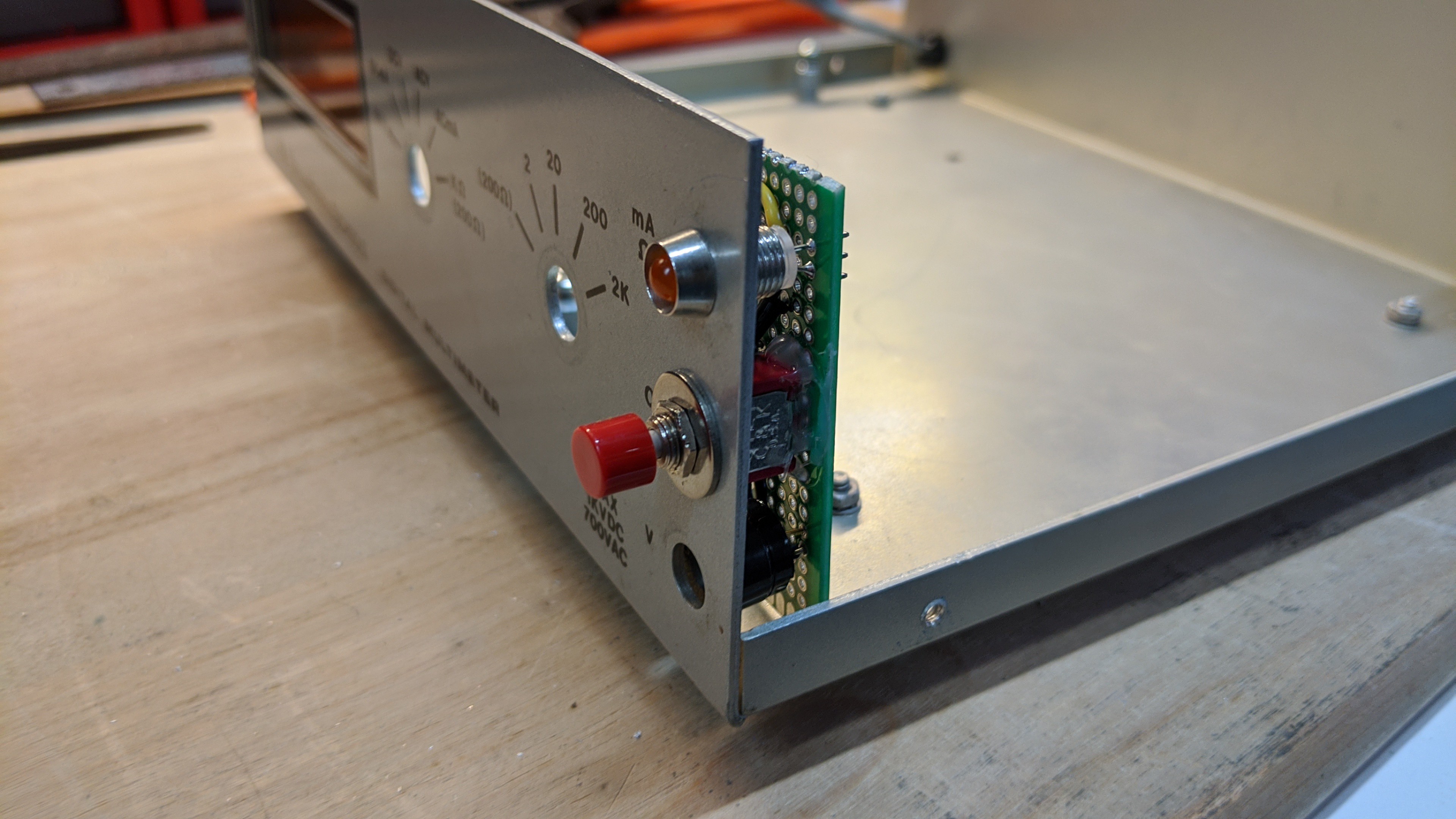
Lastly, I cut another small piece of proto-board and soldered up a connector, LED, push button, and speaker to it so they lined up with the holes in the case.
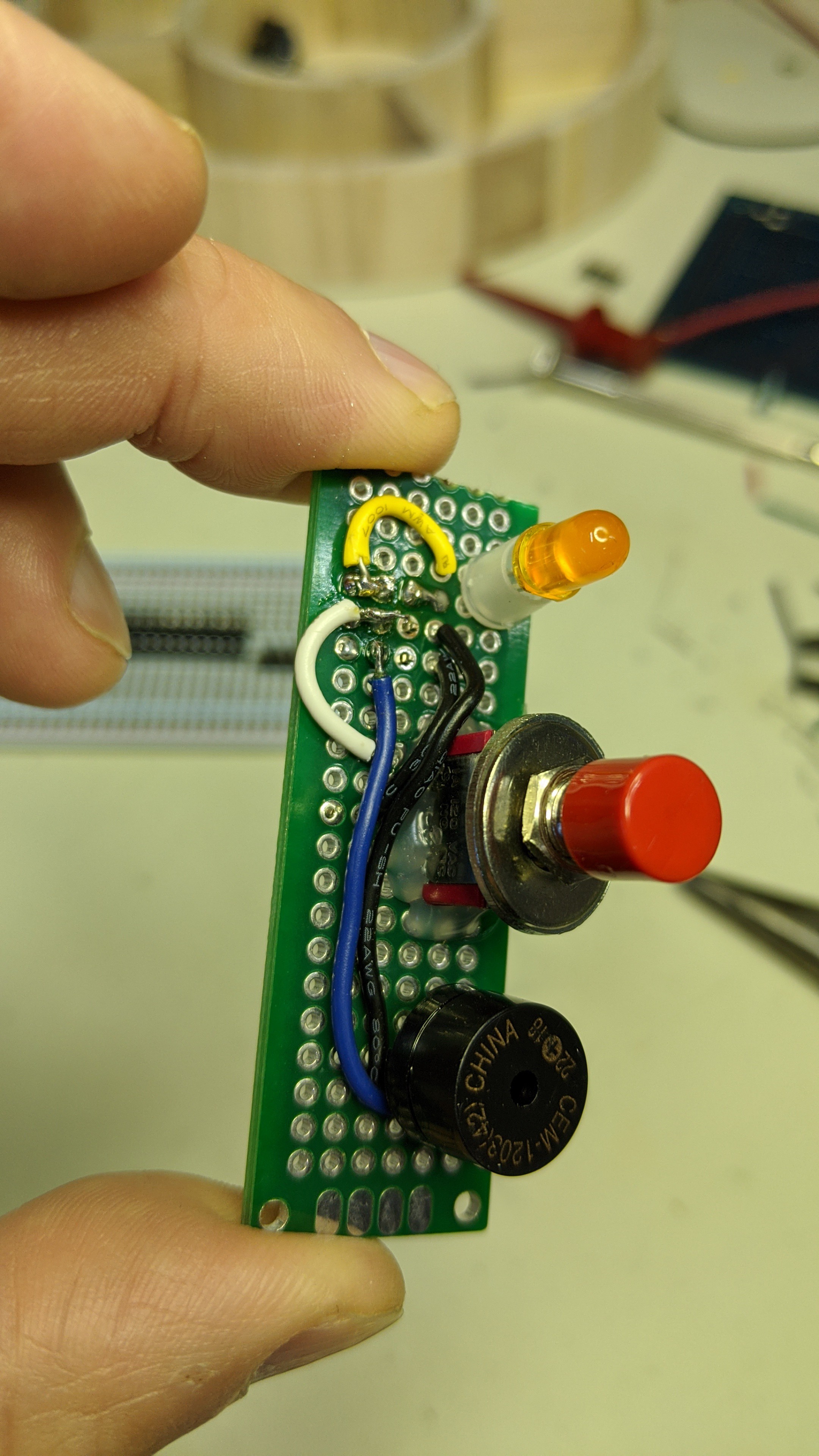
It looks like this installed.
It Speaks!
With all that done, how do I get sound out of a ATmega328? The short answer is you use the PWM peripheral to output a signal (wave) that drives a speaker. In fact, the outputs on the AVRs are stout enough to drive a tiny speaker directly. I think Sparkfun and/or Adafruit sell the little speakers. The sound is a little quiet, but it's pretty good. In this latest build of the dice tower, I added a simple LM386 op amp circuit to drive a slightly bigger 8 ohm speaker for better sound. I also inserted a simple RC low band pass filter circuit between the timer compare output pin on the AVR and the op amp. I used a .01 uf capacitor with a 200 ohm resistor to filter out frequencies roughly above 8 kHz.
There's lot more details to reproducing sound involved here. But, I'm not going to try an explain all of that. I assume there are several sources on the inter-webs and text books that explain pulse code modulation or why I added a low band pass filter much better than I can.
I wrote a simple AVR PWM "driver" that sets up the ATmega's Timer/Counter 2 in fast PWM mode, sets the period to 7812 Hz at the 8 mHz internal oscillator clock rate, and loads 8 bit pulse code modulated (PCM) data from the program space (flash) into the comparator each cycle.
At this point, I had a dice tower that could play PCM sound data. I sampled the sound of dice tumbling down one of my "analog" dice towers and set it up to play when the pushes the roll button.
So how do I make it talk?
This isn't a full speech to text implementation. It can only speak the numbers 1 through 999 and pronounce "Dee" as in the letter "D" or "roll six D six for damage on that fireball." But, that's still pretty good for a little 8 bit microcontroller with just 32K of Flash, 2 K of RAM, and a simple built-in PWM peripheral. For perspective, that 32K of Flash will store just 4 seconds of 8 bit PCM encoded mono sound sampled at ~8 kHz. Try to count from 1 to 999 out loud in less then 4 seconds and make it easy to understand. It ain't gonna happen.
So, I figured I could just sample the unique words that are used to say the numbers one to nine hundred and ninety nine. I started by snagging an older version of the Microsoft text to speech demonstration application TTSApp. I liked the dated quality of the speech generated by the app and it was very easy to generate wave source files of the words I wanted. I could even control how fast the words were spoken. I generated .wav files for all the words that represent the numbers 1 to 20 and Thirty, Forty, ..., and Ninety. I then used the Audacity application on my little Linux notebook to max out the sound levels on the samples.
Next, I needed to get those .wav files into the ATmega328's flash memory. The easiest way to do that with the minimum amount of additional program memory overhead is to convert the data the sound files represent into C arrays and link that code with my application. There are likely some existing programs out there to do that, but I decided to write one myself. I figured there was a good chance I might want to do some additional processing on the data.
I wrote a simple Linux command line application in C to convert the .wav files into text files that represent the data as C arrays of type uint8_t. To save the headache of trying to figure out how to decode a .wav file and add some additional features like converting mpeg and other sound/video files and changing the sample rate from any source sample rate to a user provided rate, I piped the output from the FFMPEG application into my app and output the text file with all the C required stuff. Now my source file could be just about any type of media file and I could convert it to mono 8 bit PCM data at any sample rate I chose and my little command line app would spit out some statistics like the total size of the data.
I used the new app to build a single .h file with the C arrays from the .wav files I mentioned above. Once it completed, it reported that the total length of the sampled sound was over 8 seconds and the memory required to store it would be more than 64K. At that point, I just about gave up on the whole speech idea. But, I decided to see what I could do with a little compression on the data.
First, I added simple run length encoding. This lossless form of compression simply substitutes a reserved value followed by a count whenever it comes across more than one instance of the same value sequentially in the source data. So, if the source .wav file had the value 0x80 ten times in row it would replace that with two bytes. The first byte would be the reserved token 0x00 and the second byte would be 0x0a (the value ten). In this manner, 10 bytes in the source data is stored as 2 bytes. 8 bit PCM sound data represents a wave form. Values greater than 0x80 represent a "positive" pulse and values less that 0x80 represent a negative pulse. If all is quiet in the original source data, the value 0x80 is repeated at the sample rate. Looking at the source data for the sound samples I could see this 0x80 value repeated from time to time. Very few other values seemed to be repeated more than twice. I decided that I would reserve the token 0x00 followed by another byte representing 0-255 bytes of repeating values 0x80. I coded this up and re-ran my little command line application. I got about 20% - 30% compression on my original sources.
This wasn't enough but it was a pretty good start. I looked at the raw source data again and saw that sound waves didn't instantly return 0x80 as the source data got quieter. It tended to bounce around the value 0x80 plus or minus a small number. These low energy pulses would barely be audible and might not even move the diaphragm on my cheap little speaker. So, I changed the app again. Now I could provide a value that would be used as a +/- deadband around the value 0x80. I rebuilt the .h file from the original .wav sources using a deadband value of +/- 5. This gave even better compression. I then modified my AVR application to recognize this new token and expand it appropriately as it loaded bytes into the counter comparator for the PWM. I played one of the sampled words and it sounded great. I then tried to link all the words/numbers. Unfortunately, my data was still just a little too big.
So, I rebuilt the .h file one more time using a deadband value of +/- 7. This just barely fit when I linked all the numbers and the sound for "D". I had like 100-200 bytes to spare. But how would it sound? Well, scroll to the bottom of this log post and hear for yourself.
The rest was just a matter of selecting and playing the sound samples sequentially to represent the numbers selected by the user and resulted from the pseudo-random number generator.
And it works...
Discussions
Become a Hackaday.io Member
Create an account to leave a comment. Already have an account? Log In.