 John Anderson
Now it's time to solder the connections to the nixie display drivers, lamp transistors/drivers, and the current limiting resistor for the LED result indicator.
Do these steps in the order presented and it will make the soldering easier.
First, determine where to connect the microcontroller digital outputs to the 1's Nixie digit. For this, I happen to have the original assembly manual for these digital multi-meters.
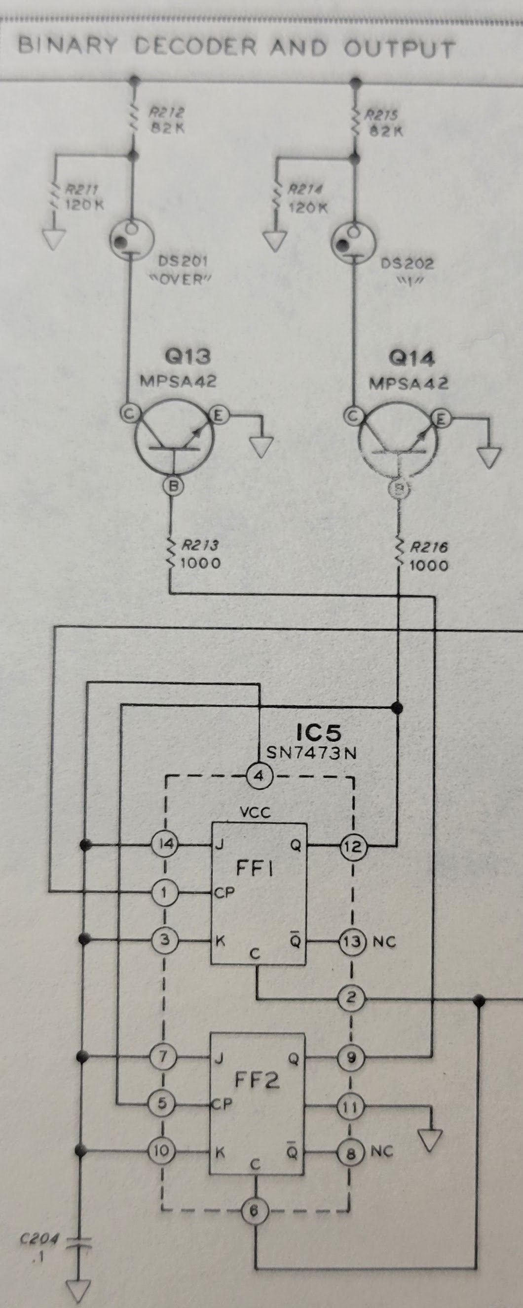
And it has a full schematic of the circuit board.
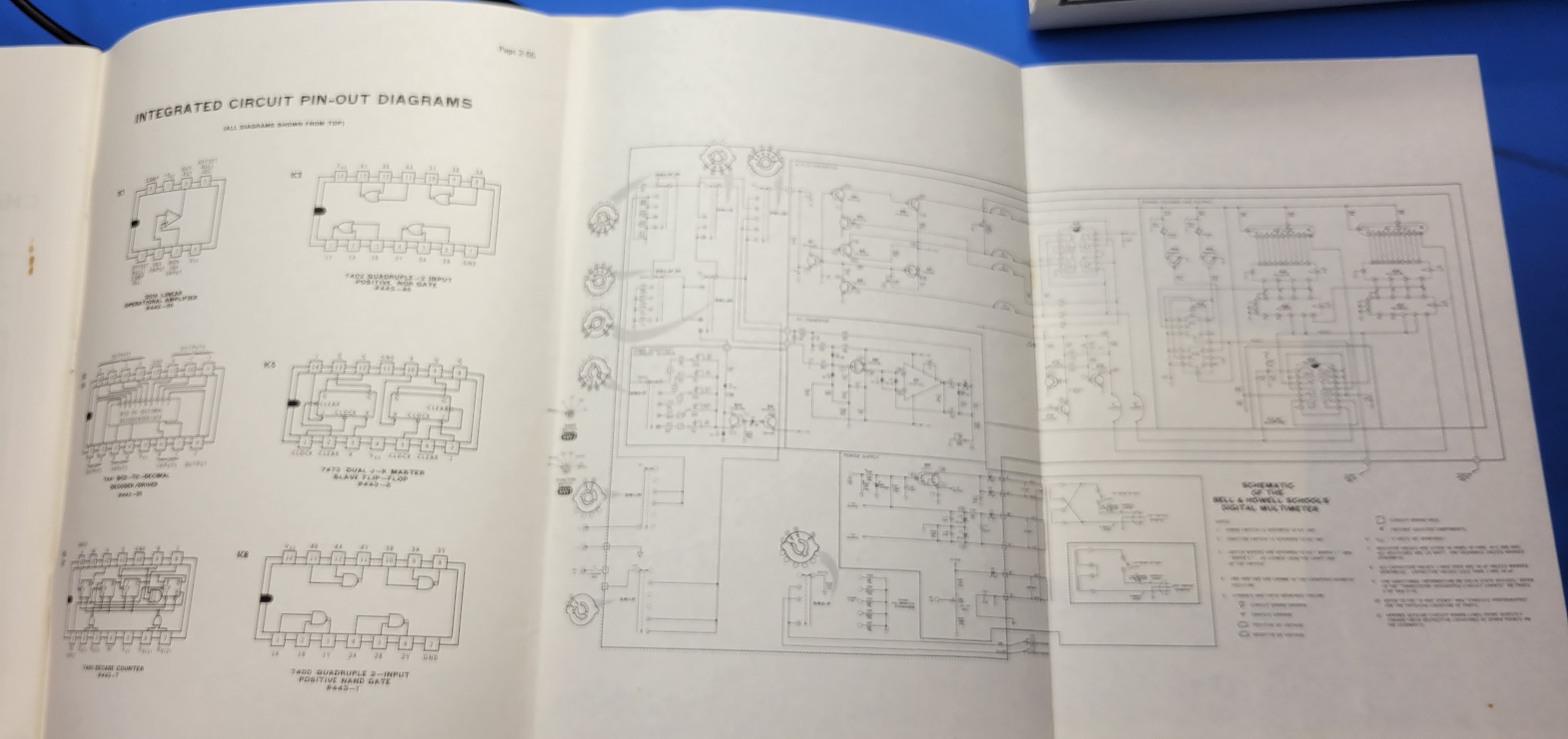
I won't bore you with all the details. But, we are interested in how to drive the Nixie displays. So, here's the relevant part of the schematic. It shows how the original 7490 decade counters (IC6 and IC7) connected to the 7441 BCD to decimal decoder/drivers (IC3 and IC4).
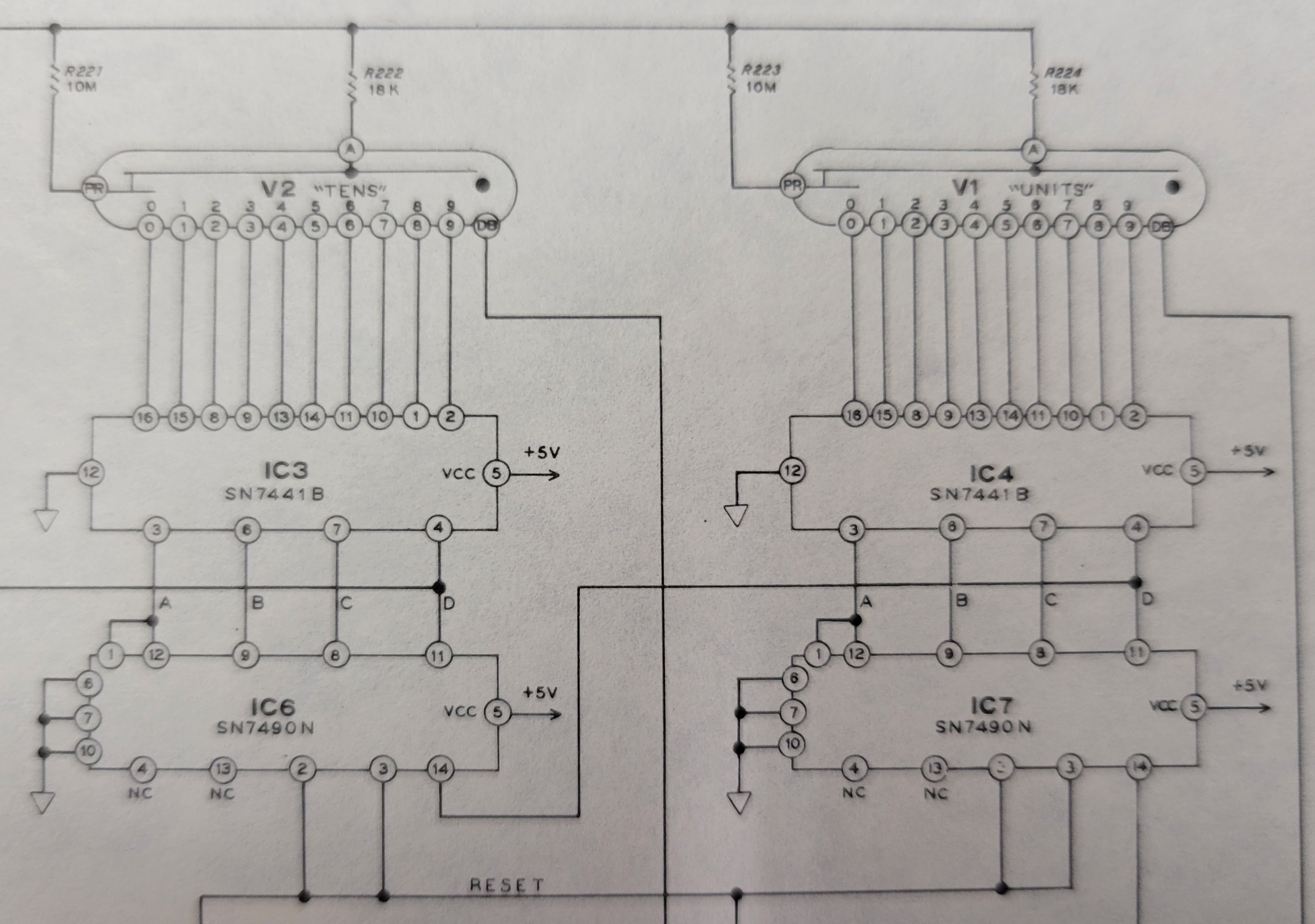
The controller board plugs into the sockets that used to contain IC6 and IC7. The interface here between the old 7490 decade counters and the 7441 decoder/drivers is TTL logic levels. This is compatible with the digital outputs on the ATmega 328P microcontroller. So, wiring this up will be simple. The outputs from the microcontroller can directly drive the inputs on the 7441 decoder/drivers.
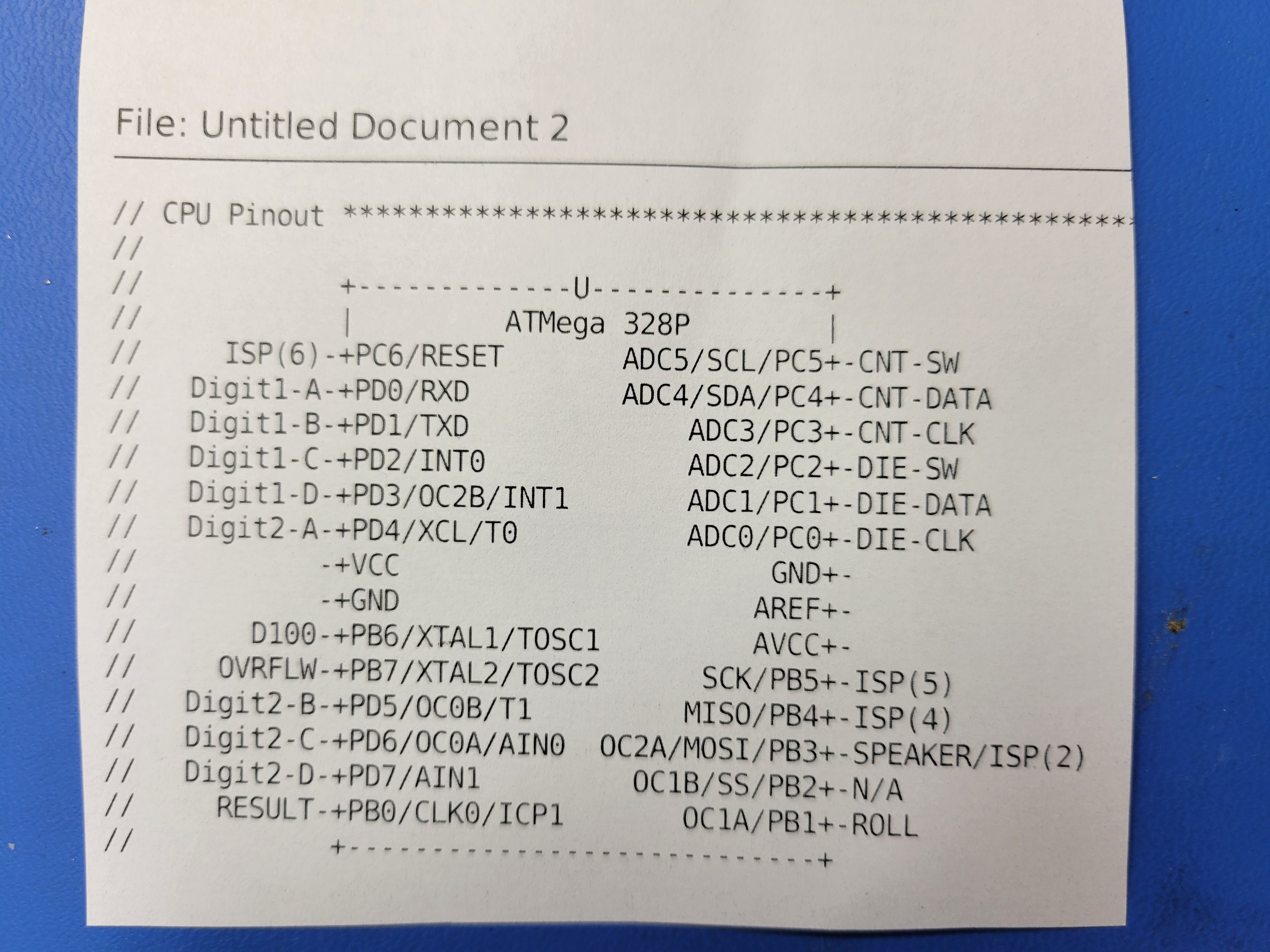
Here's the pinout for the microcontroller. Pins 2-5 are the outputs for the 1's digit.
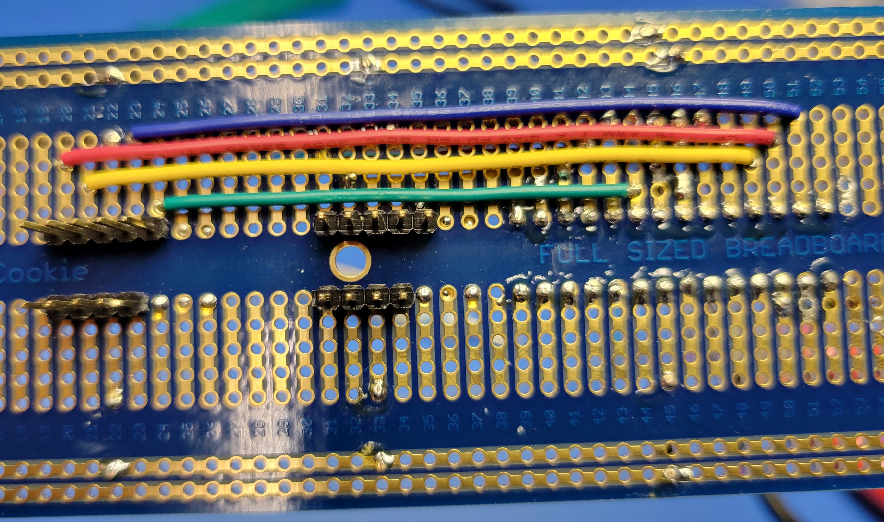
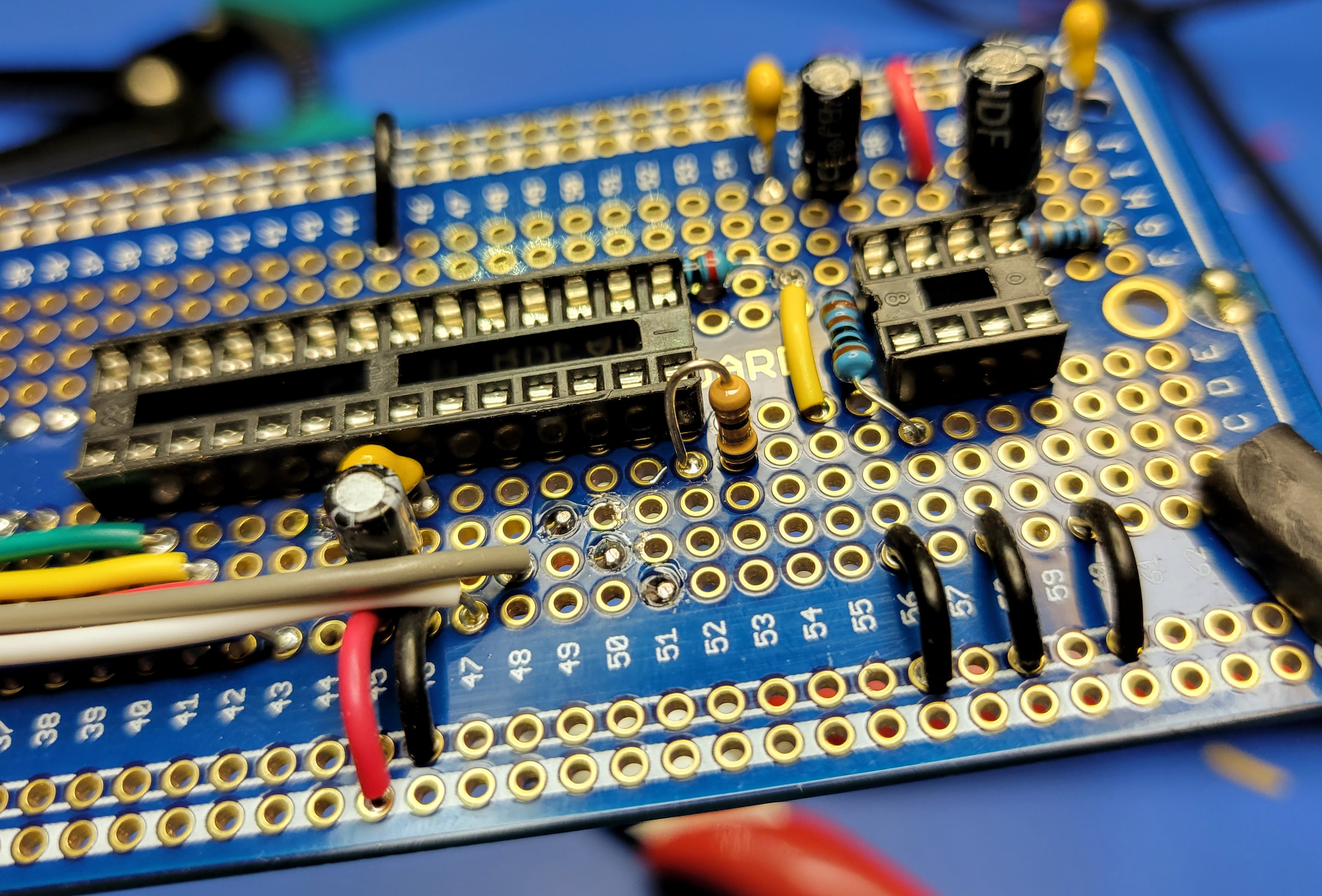
On the controller board, it looks like this for the 1's digit Nixie display.
- Pin 2 (row 40 column D) of the microcontroller connects to pin 12 (row 35 column D) of IC7
- Pin 3 (row 41 column C) of the microcontroller connects to pin 9 (row 32 column C) of IC7
- Pin 4 (row 42 column B) of the microcontroller connects to pin 8 (row 31 column B) of IC7
- Pin 5 (row 43 column A) of the microcontroller connects to pin 11 (row 34 column A) of IC7
Run these wires on the top side of the board and solder from the bottom side.
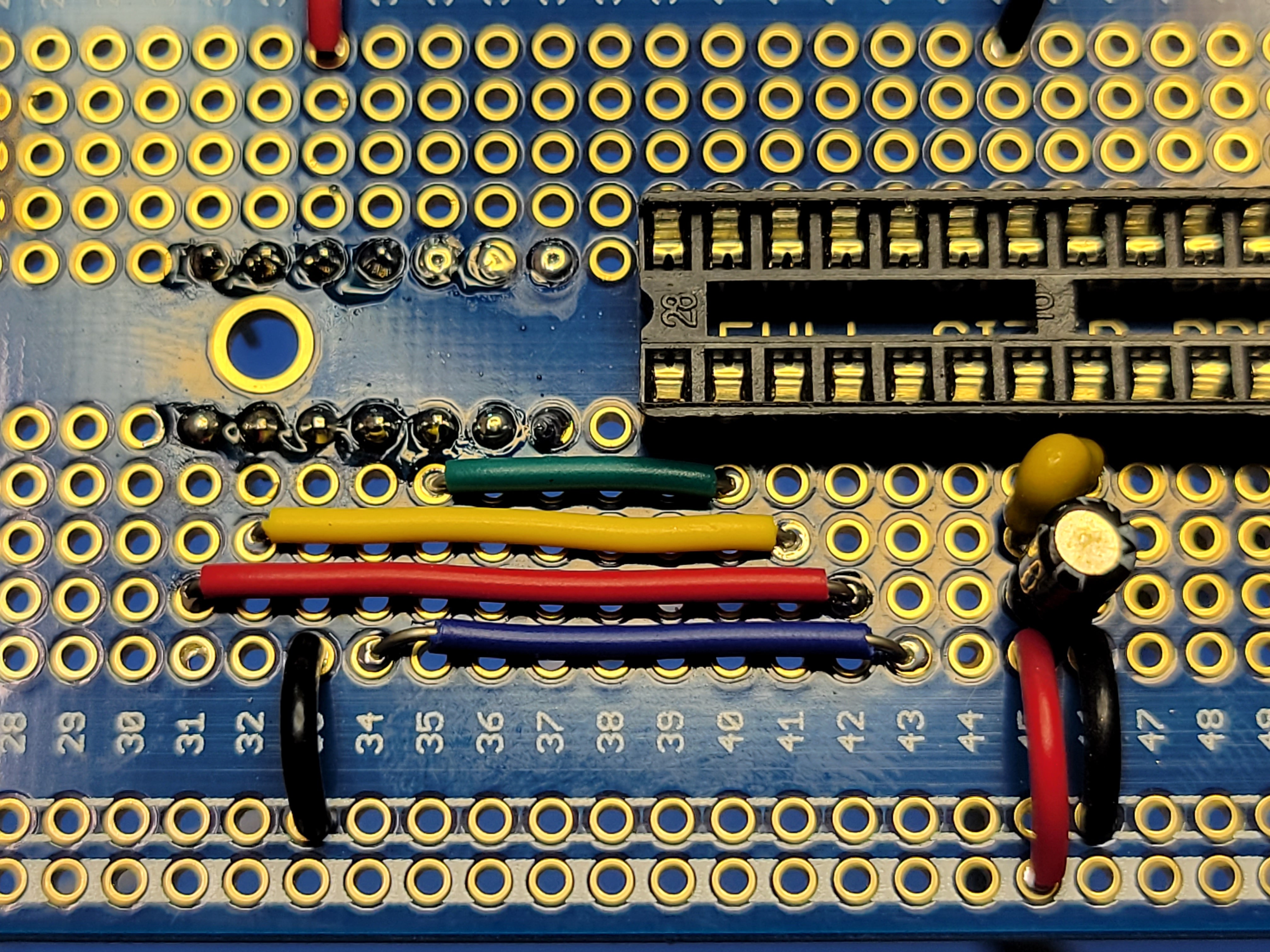
Next, connect the 100 digit (it's just a neon lamp representing the digit 1) and the overflow indicator (another neon lamp).
As you can see from the original schematic, the 1's digit is driven by pins 5 and/or 12 on IC5. The overflow indicator is driven by pin 9 on IC5. Again, these are TTL level compatible. So, they can be driven directly by the microcontroller.
It looks like this on the controller board.
- Pin 9 (row 47 column A) of the microcontroller connects to pin 5 (row 3 column G) of IC5
- Pin 10 (row 48 column B) of the microcontroller connects to pin 9 (row 2 column B) of IC5
In hindsight, I could have connected 100's digit to pin 12 of IC5 and saved the jumper wire between rows 10 and the wire from row 10 column G to row 3 column G. That would have required a 5 pin header instead of the 4 pin header I had installed. Lesson Learned: Use a pair of 7 pin headers for the IC5, IC6, and IC7 socket connections.
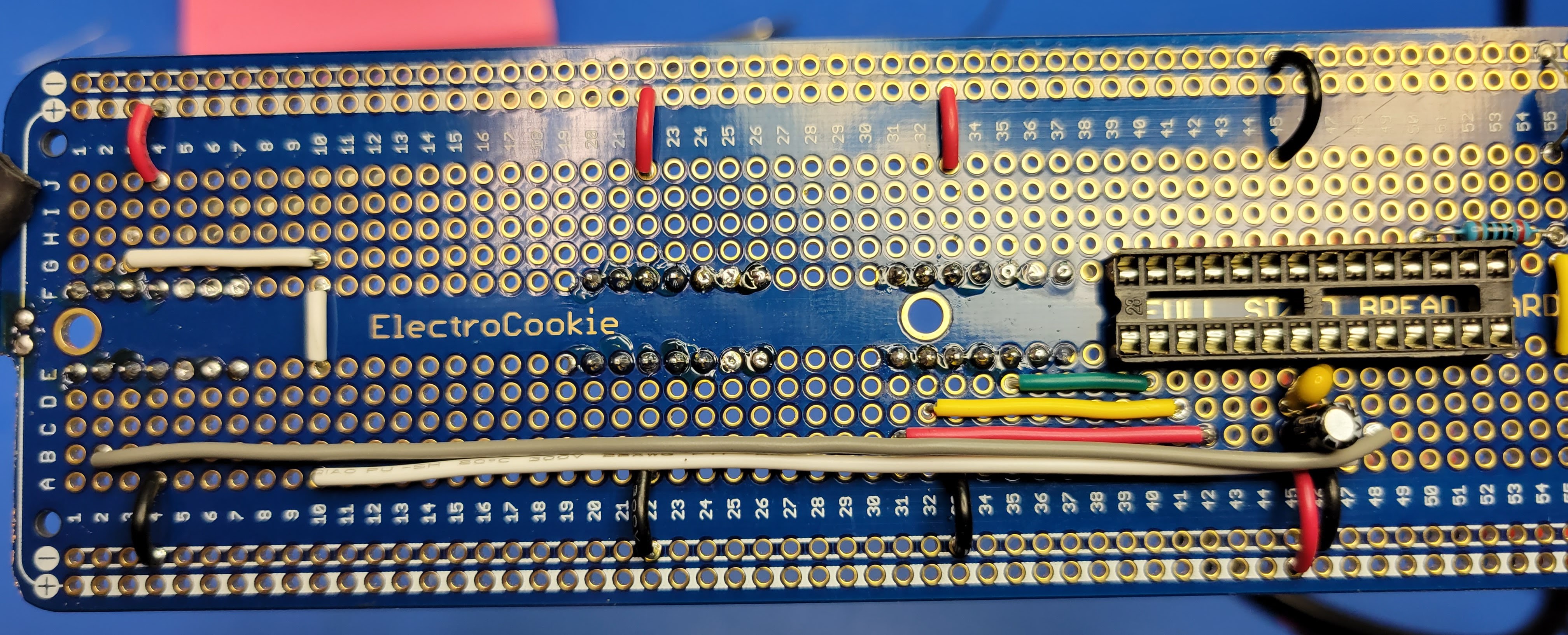
Now, wire up the connections for the 10's Nixie digit. These wires will be run on the bottom side of the board and soldered from the top side. This will keep everything cleaner.
It looks like this on the controller board.
- Pin 6 (row 44 column D) of the microcontroller connects to pin 12 (row 24 column D) of IC6
- Pin 11 (row 49 column C) of the microcontroller connects to pin 9 (row 21 column C) of IC6
- Pin 12 (row 50 column B) of the microcontroller connects to pin 8 (row 20 column B) of IC6
- Pin 13 (row 51 column A) of the microcontroller connects to pin 11 (row 23 column A) of IC6
Lastly, solder up the current limiting resistor for the result LED indicator. I am using a 5mm green LED for this. So, I used a 68 Ohm resistor. Pin 14 on the microcontroller drives this indicator. So, solder the resistor from pin 14 (row 52 column D) to row 53 column D. Row 53 columns A, B, C will connect to the positive lead on the LED when we wire up the external switches, speaker, and LED indicator in the next blog.
With that, all of the visual indicators are wired up.
Discussions
Become a Hackaday.io Member
Create an account to leave a comment. Already have an account? Log In.