 Guillermo Perez Guillen
MKR WAN 1300
Features:
- MKR WAN 1300 is a powerful board, and Its the ideal solution for makers wanting to design IoT projects with minimal previous experience in networking having a low power device.
- The Arduino MKR WAN 1300 includes Lora connectivity that can perform very long-range transmission operations consuming low power. The MKR WAN 1300 is incorporated with the Microchip® SAMD21 which is a low-power processor.
- A range of technologies available for the communication between IoT devices including WiFi and Bluetooth. But there is one major problem with these technologies – they consume a lot of power.
- The operating voltage of the circuit is 3.3V while the voltage through Vin and USB is 5V.
- There are total 8 digital I/O pins incorporated on the board while the number of analog pins is 7. And the pins that can be used for the PWM motor control are 12.
- The board controller comes with a flash memory of 256KB while the SRAM memory is 32KB. While the SRAM memory is reserved to generate and manipulate variables when it runs.
- Interface this MKR board with Arduino IoT cloud that guarantees safe communication between all connected devices.
- The carrier frequency of this board is 433/868/915 MHz which is termed as the frequency of a carrier wave, calculated in cycles per second, or Hertz.
Pinout:
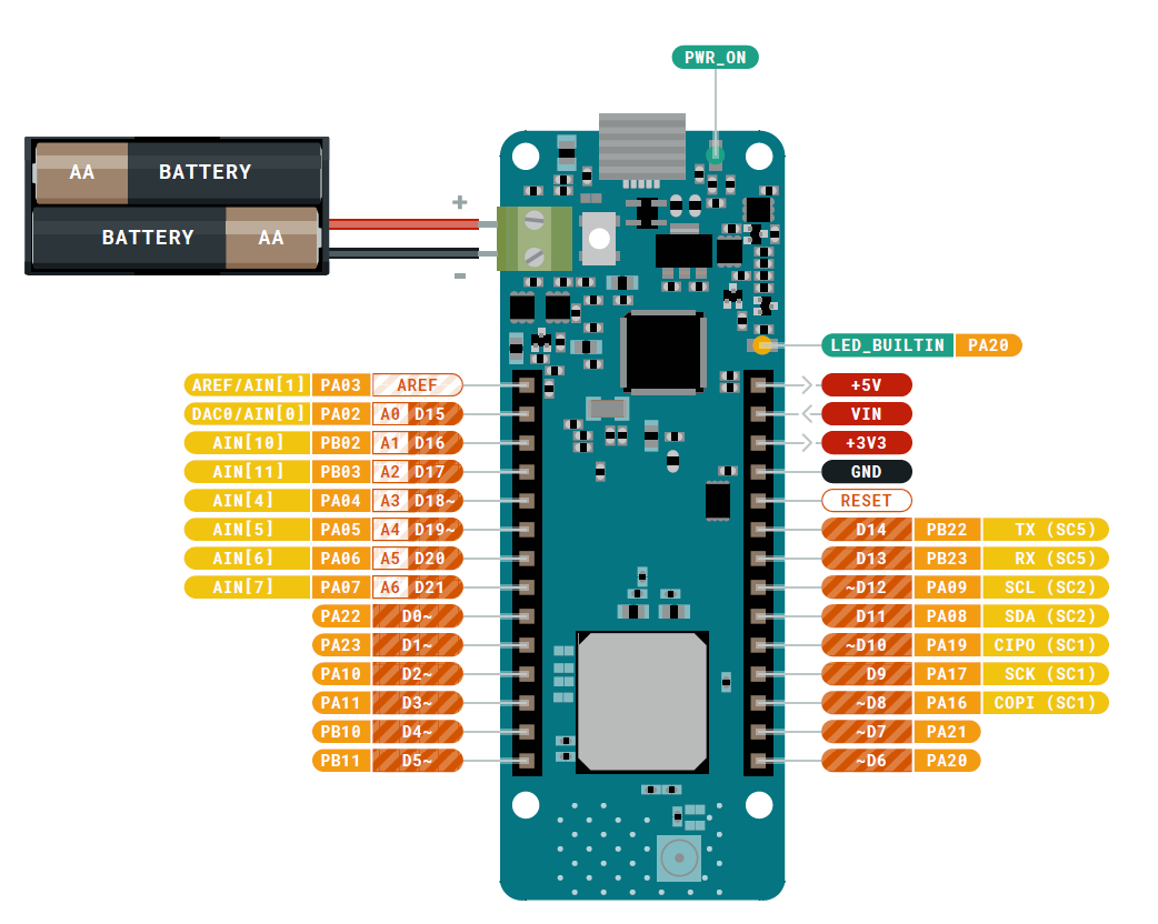
Pin Description:
- Analog Pins: There are 7 analog pins available on the board. These pins can get any number of values.
- Digital Pins: Total 8 digital pins are installed on the board which you can use either as an input or output based on the requirement. These pins offer only two states HIGH or LOW.
- PWM Pins: The number of pins that can be used as PWM pins is 12. These pins generate analog results with digital means when PWM pins are activated.
- UART Pins: The board contains two pins Rx and Tx for the serial UART communication. The Rx line is used to receive the serial data and the Tx pin is used to transfer the serial data.
- SPI Pins: This device also offers an SPI communication protocol that is mainly used to develop communication between the microcontroller and other peripheral devices like sensors. Two pins: MISO (Master Input Slave Output) and MOSI (Master Output Slave Input) are employed for SPI communication between devices. These pins are used to send or receive data by the controller.
- 12C Pins: The WAN board comes with a two-wire communication protocol known as the I2C protocol. This features two pins SDL and SCL. The SDL is a serial data line that carries the data while SCL is a serial clock line that is mainly employed for the synchronization of all data transfer through the I2C bus.
PROGRAMMING:
This board is programmed using Arduino IDE software which is an official software to program all Arduino boards: https://www.arduino.cc/en/software
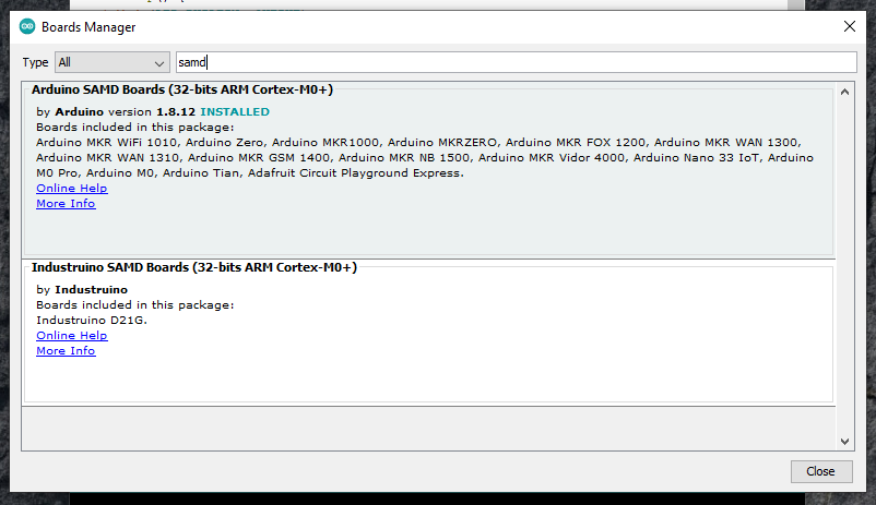
If you want to program your MKR WAN 1300 you need to add the Atmel SAMD Core to it. This procedure is done selecting Tools menu, then Boards and last Boards Manager as shown below.
Now that the SAMD Core is installed, you can connect the board to the computer using a standard USB cable. Select your board type and port From Tools select the Board Arduino MKR WAN 1300. From Tools select the Board Arduino MKR WAN 1300.
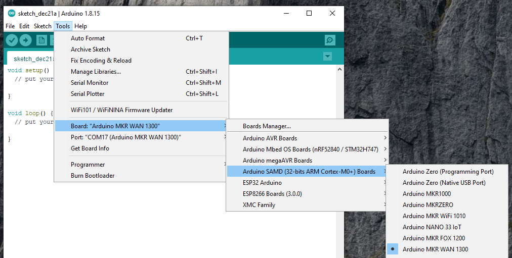
Check the serial communication port.

Now before you get started you will have to update the latest firmware on the MKR 1300 using the MKRWANFWUpdate_standalone sketch here: https://github.com/arduino-libraries/MKRWAN/tree/master/examples/MKRWANFWUpdate_standalone
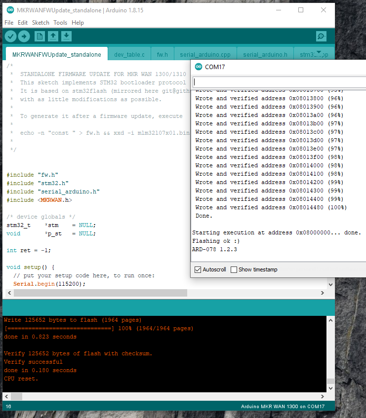
After these steps, you are ready to start programming your MKR WAN 1300 board. For example you can try the blink sketch.

Discussions
Become a Hackaday.io Member
Create an account to leave a comment. Already have an account? Log In.