 Guillermo Perez Guillen
In this part of my project, the challenge is to connect my LoRa network to an IoT provider, but one with cost-effective. Below is the schematic diagram.
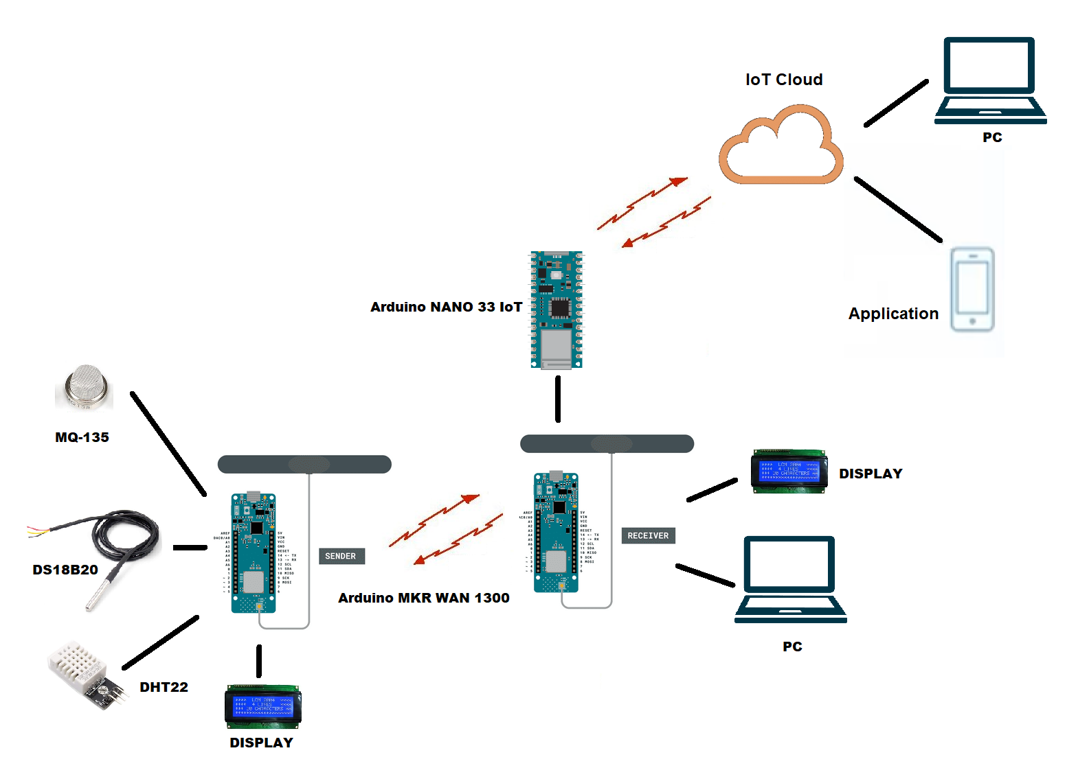
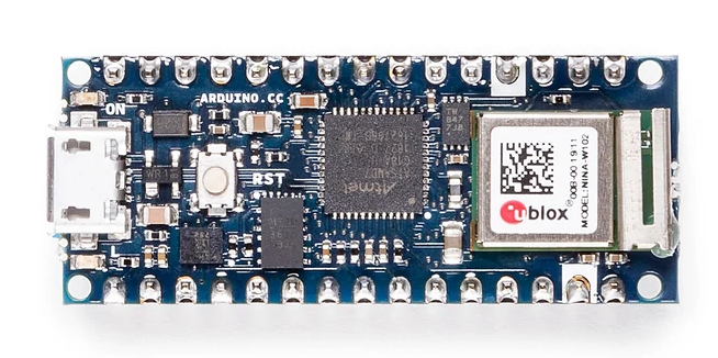
In this project I am going to connect my LoRa network with an IoT provider through the Arduino NANO 33 IoT board. Reason:
Its an economic solution, since the Arduino NANO 33 IoT board has an average cost of $20.70 USD.
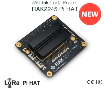
On the other hand, the Gateway Lora RAK2245 board has a price of: $ 154.55 USD.
Creating a New Serial Port to the Arduino MKR WAN 1300 Board
When I checked out the ATSAMD21 chip (the processor used in the Arduino MKR WAN 1300 board), I was very happy to see that the chip has 6 "SERCOM"s, a.k.a SERial COMmunication modules. Each one of these modules can be used for I2C, SPI or Serial. That means you can have 3 UART's & 3 SPI's, or maybe 2 SPI's and 4 I2C's. Basically, you have a ton of options for adding more hardware support for the most common 3 chip-to-chip protocols.
UART has only 2 pins, RX & TX. UARTs are a real pain to emulate or bitbang due to their very precise timing and their asynchronous RX lines are very difficult to do if you dont have hardware interrupt pins available. For that reason, being able to create new Serial's is awesome.
Now, what I need is to create a new serial port on the Arduino MKR WAN 1300 board to connect it with the Arduino NANO 33 IoT board via serial port. In this way the Arduino NANO board will receive the data from the sensors and can send them to any IoT provider.
How Serial is Created Now
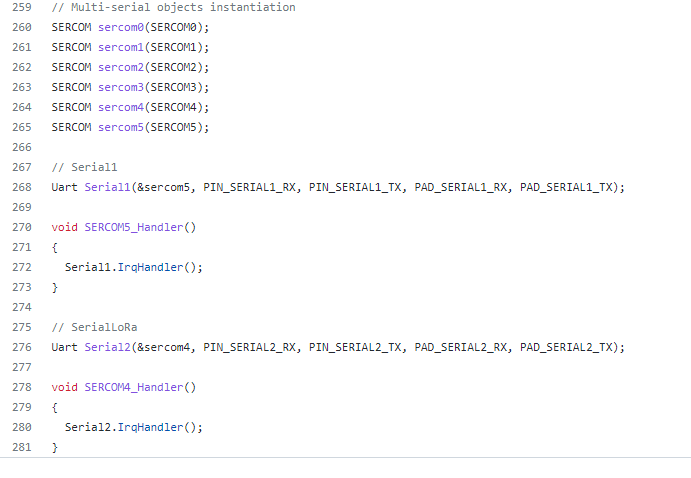
You can find the actual code that is used to create the "Serial" SERCOM in variant.cpp
You will see the serial objects on:
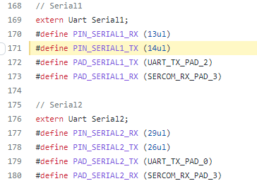
The actual definitions of those macros is available in variant.h
OK so let's make a new Serial SERCOM already
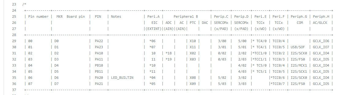
I want to make a Serial! Lets try creating a new SERCOM and testing it out. Let's make a Serial device on SERCOM #1, lets look at what pin muxing options we've got:
| PIN number | PIN arduino | SERCOM |
| PA16 | D8 (MOSI) | SERCOM1.0 |
| PA17 | D9 (SCK) | SERCOM1.1 |
| PA19 | D10 (MISO) | SERCOM1.3 |
| PA18 | D24 (USB) | SERCOM1.2 |
Rules:
- Tx only works on PAD 0 and PAD 2
- RX works in any PAD
I have selected next pins:
- D8 FOR TX
- D9 FOR RX
In the next chapter I will show you how to program this data into the Arduino MKR WAN 1300 receiver board.
Discussions
Become a Hackaday.io Member
Create an account to leave a comment. Already have an account? Log In.