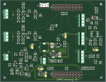
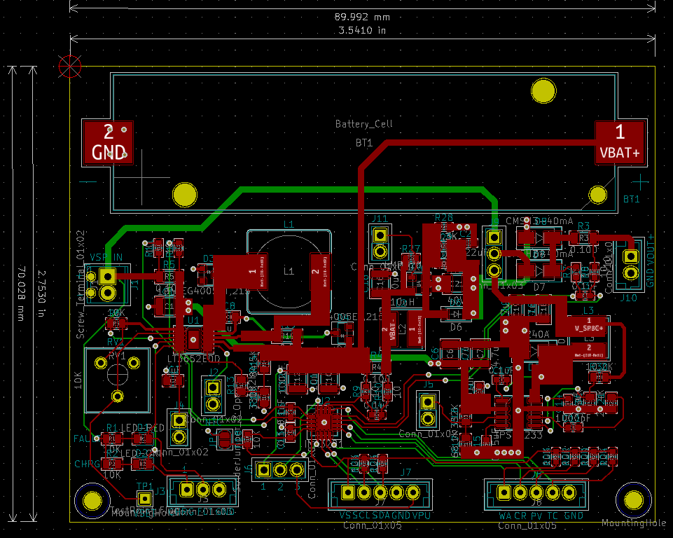
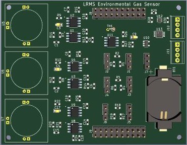
The LRMS analog I/O board is intended for analog sensors or custom sensor designs that do not have digital interfaces. In addition to the analog I/O the board also supports I2C and TTL UART connections.
A high speed amplifier with a sample and hold peak detector with a DC boost converter has been included for photo detectors such as a silicon photo-multiplier.
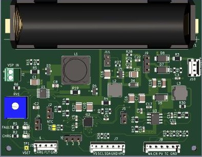
Board Connectors:
J1 & J2 : Two Configurable nano power operational amplifiers, can be configured as Differential, Single ended Non-Inverting/Inverting. Each amplifier output is buffered with a unity gain amplifier to the ADC channels.
(6Kz unity gain, 350nA per channel)
J3 : One high speed non-inverting operational amplifier with sample and hold peak detector.
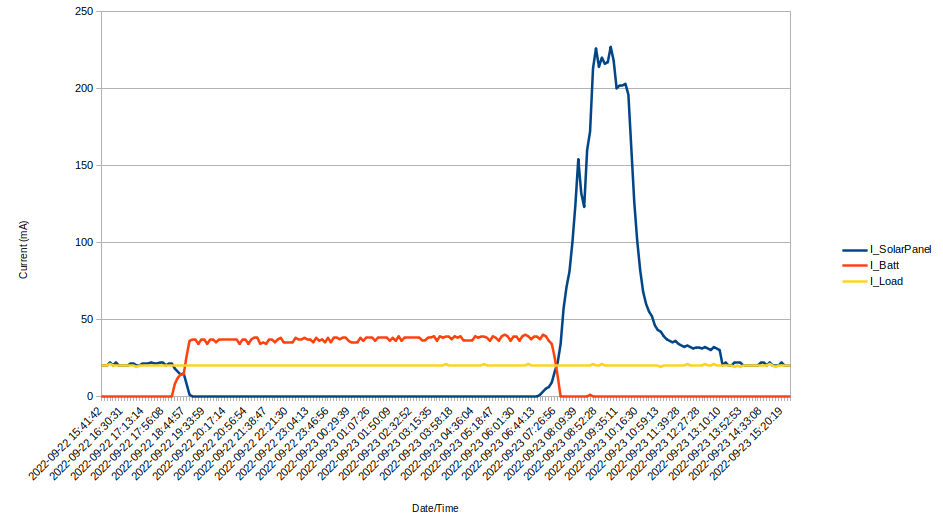
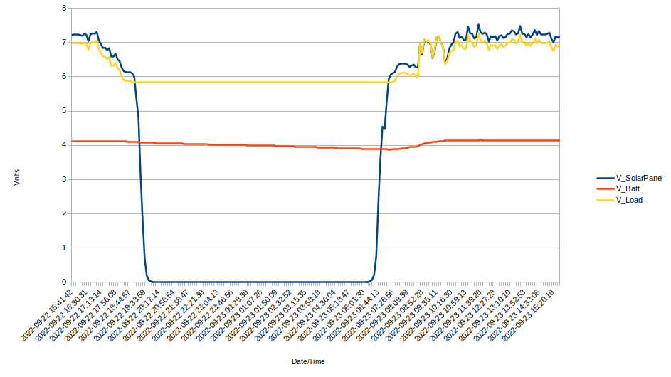
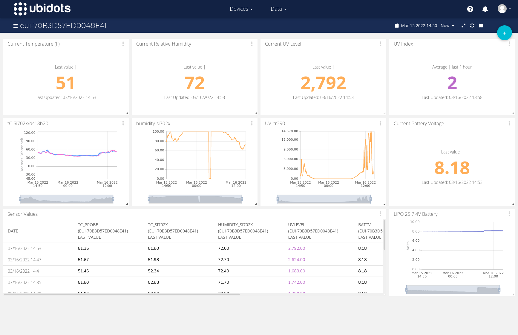
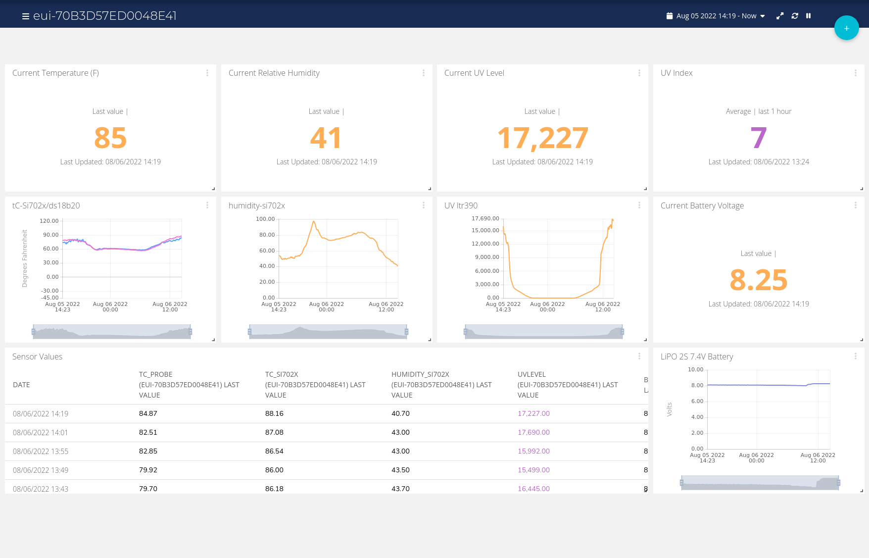
Revision 1 of the LRMS monitoring station has been continuously operating outdoors for 8 months beginning January 2022. The sensors for the station are the usual temperature and humidity sensors found on many projects but I added a UV sensor to make the R1 station more unique and test the hardware and software.
Here are a couple of screen shots showing the data collected from LRMS R1
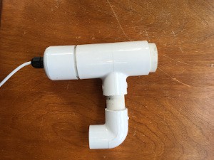
The sensors used are a DS18B20 temperature probe, Si7021 temperature and humidity sensor, and a LTR390 UV sensor in a PVC T pipe fitting.
UV & Humidity Sensor Module
The UV sensor has a 20mm x 20mm fused silica window epoxied in front of the LTR390 sensor (right side of photo) to protect from weather and for maximum transmission of UV to sensor.
The Si7021 located inside of PVC L fitting.
The DS18B20 is a water proof module and is shielded from direct solar exposure with a PVC pipe section.
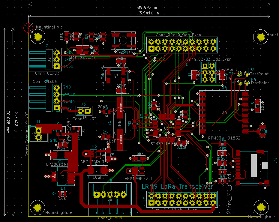
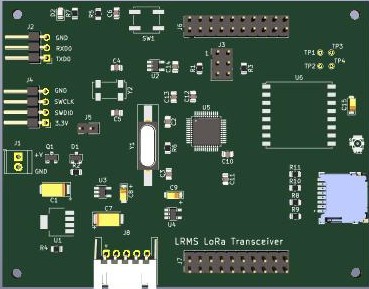
LoRa_RMS on Github has been updated to include initial release of code and installation instructions. See Software directory for details. LoRa_RMS is the directory for the system.
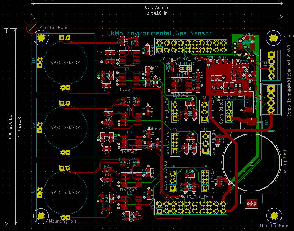
 Spec Sensors Electrochemical gas sensor array