-
1The printed circuit board (PCB)
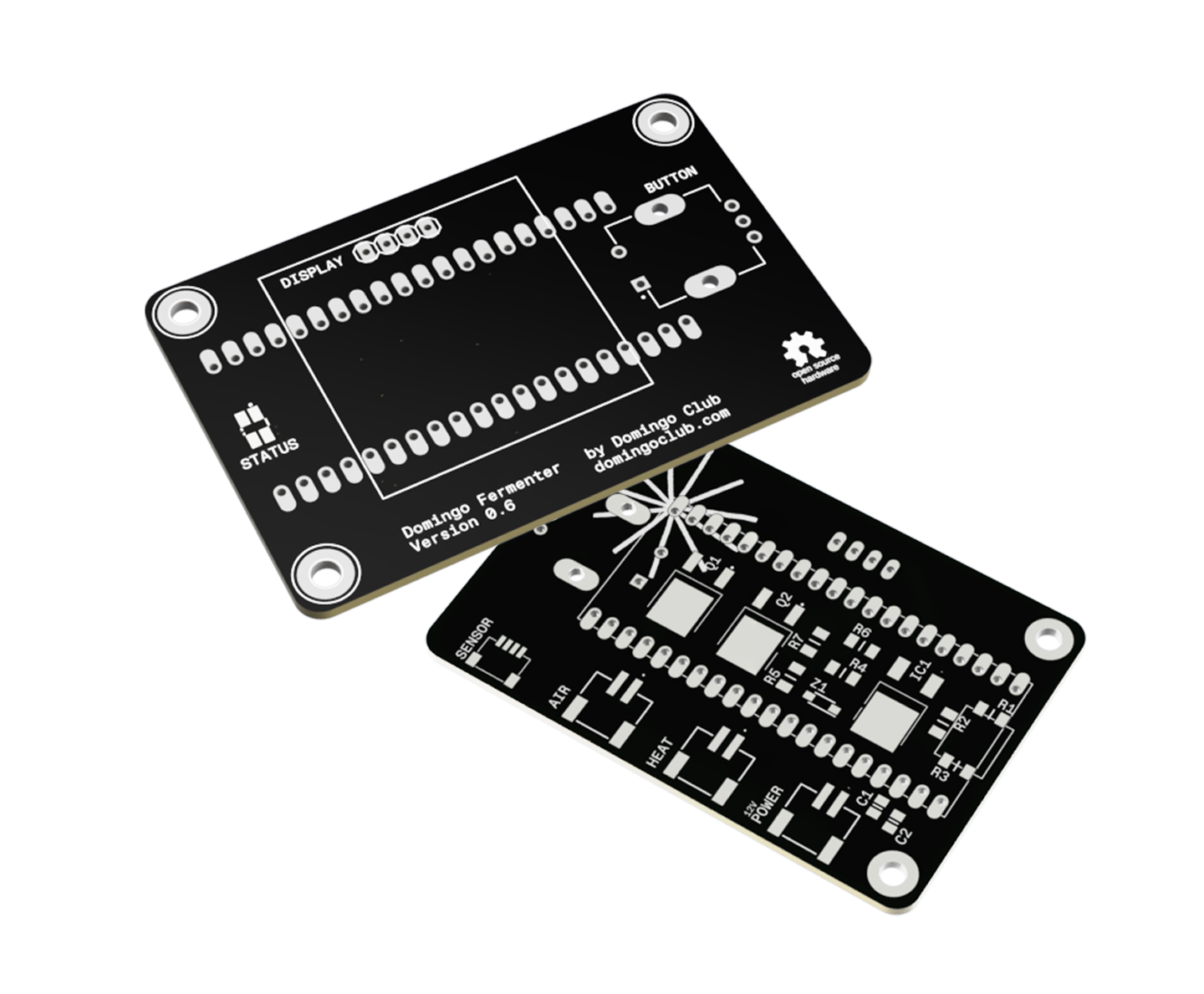
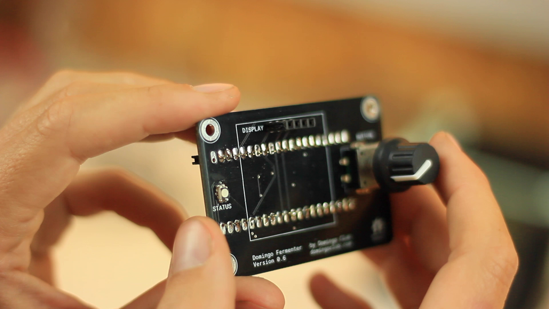
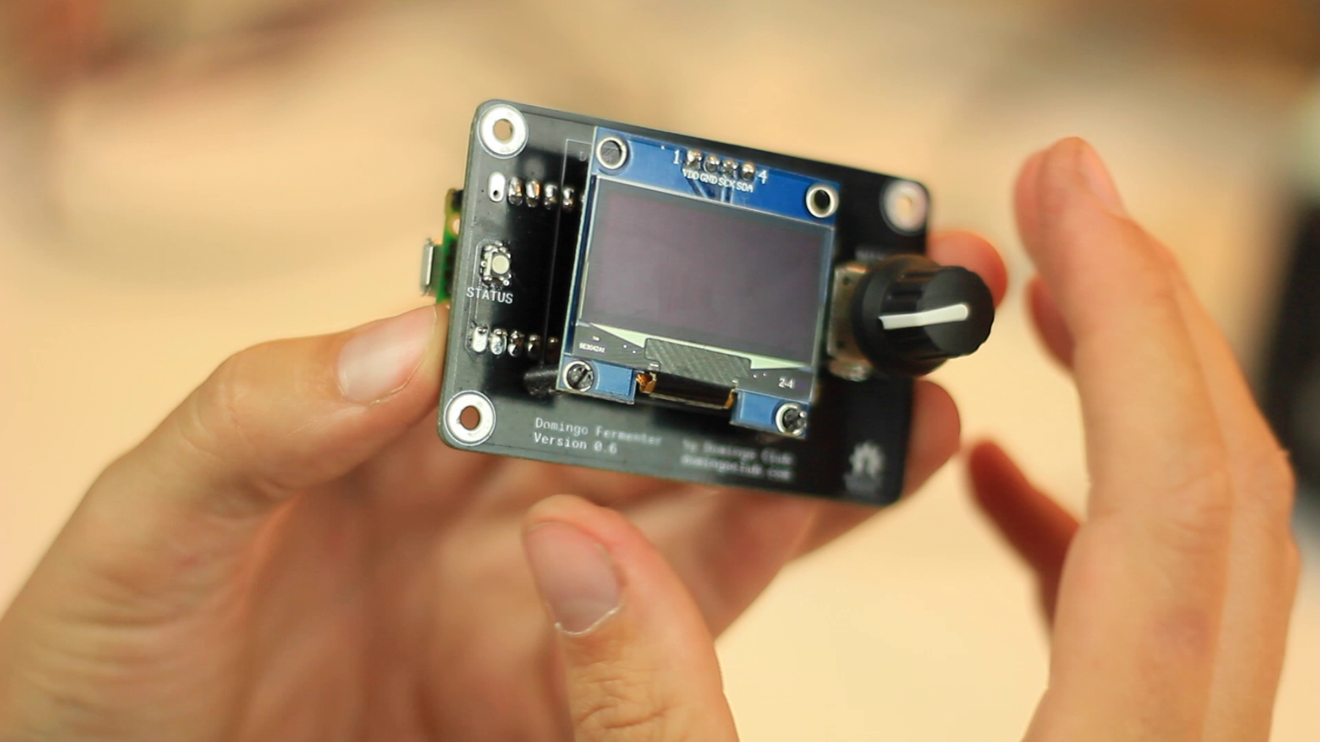
To obtain the PCB, you have three options. The first is to mill the PCB yourself using a mini-milling machine. This is what we did at the beginning of the project, but as the size of the PCB gets smaller and the number of via's increases, it becomes more and more complex, although still possible. The second option would be to send the "DOMINGO_FERMENTER_BOARD_PRODUCTION" folder to a PCB manufacturer, they would then take care of the production. The third and easiest option is to buy the PCB directly from us. You can buy it with or without components, already assembled or to solder yourself. Contact us for more details.
![]()
-
2Soldering
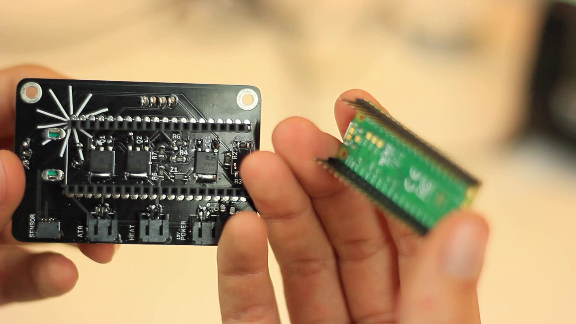
Solder the components by following the instructions printed on the PCB, or by referring to the board design or schematic file. Below is a legend of the components that could lead to confusion.
- Q1, Q2: Mosfets
- IC1: Voltage regulator
- R4, R5, R6, R7: 10K resistors
- Z1: Diode
- R1, R2, R3: 220R resistors
- C1, C2: Capacitors
Soldering tips and tricks
- We find it easiest to start soldering the small components on the back side (where the Domingo logo is) so you can keep the PCB flat on your work surface.
- The diode has a direction and therefore a line painted on its packaging. It indicates the ground. It goes to the side of the longest line seen on the PCB.
- The connectors have legs on both sides that must be soldered as well to strengthen the components in place. Especially because they will receive forces when connecting and disconnecting cables.
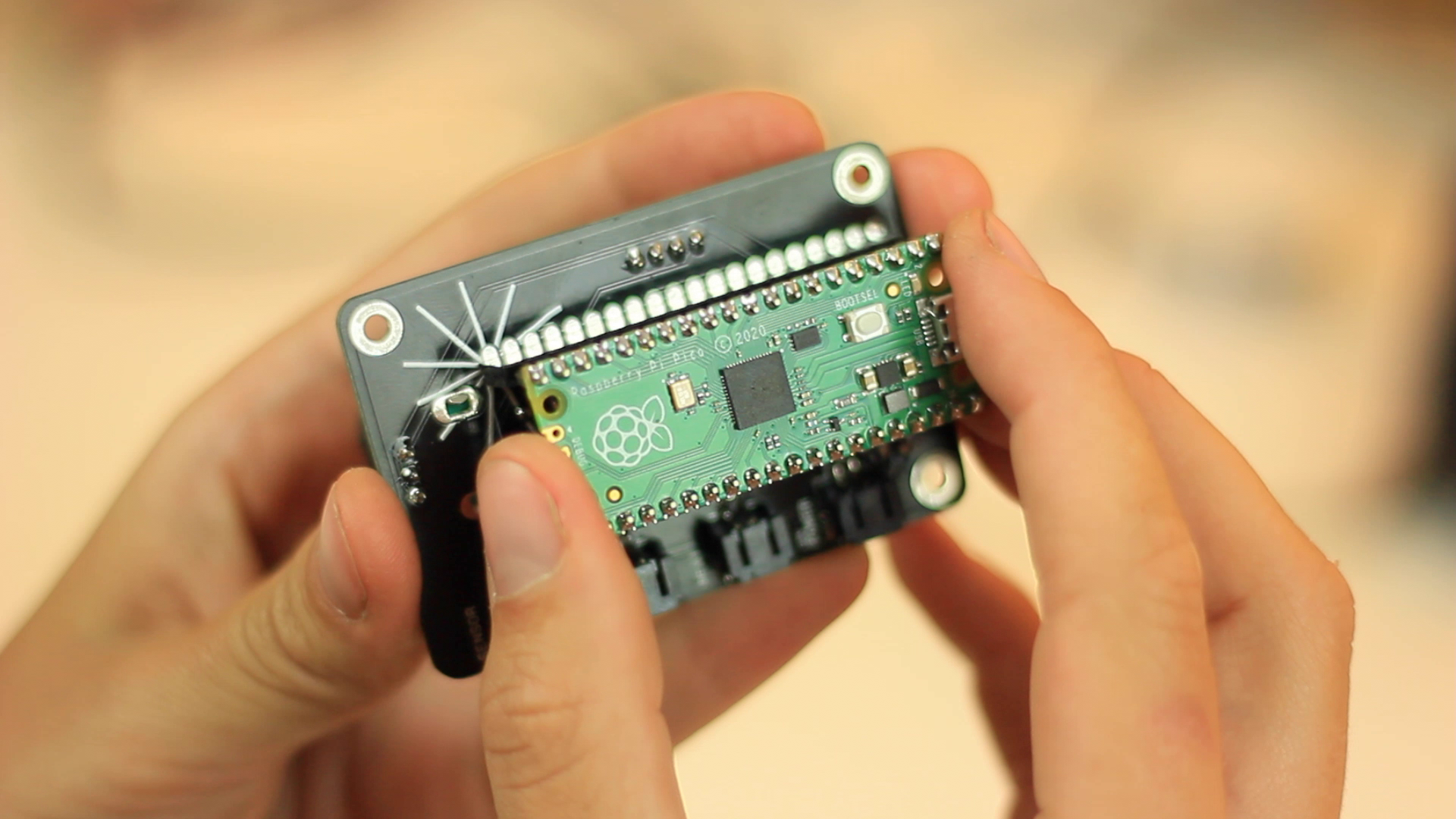
- The direction of the Raspberry Pico can be seen from the small rectangle on the PCB indicating the Pico’s USB port. Solder it accordingly.
- The RGB LED ground leg can be identified by the white dot printed on the PCB.
![]()
![]()
![]()
![]()
![]()
-
3Connecting i/o
- The JST-2Pin connectors are placed so that the 12V line is on the right pin and the GND line on the left pin. Make your cable accordingly.
- The sensor cable comes ready to use, so no potential mistakes here.
-
4Installing and updating the fermenter code
Installing CircuitPython
- Download CircuitPython from circuitpython.org
- Connect your board with a good USB data cable.
- Click on the BOOSTSEL button and connect your board to your computer. From here you should see a new device called RPI-RP2 connected to your computer.
- Now find the file you downloaded. Drag this file to the new RPI-RP2 device. If all goes well, the device should disappear for a second, then reappear as CIRCUITPY.
Bravo you have successfully installed CircuitPython on your fermenter’s microcontroller!
Installing the fermenter software
- Download the fermenter software from Github, select the latest release.
- Delete all the content present on the CIRCUITPY device
- Unzip the folder you have just downloaded and enter the software folder. Select all its contents (boot_out.txt, code.py and the lib folder) and drag it on the empty CIRCUITPY drive.
And voila, the Domingo fermenter software should be installed and working.
Troubleshooting
Let us know if any of these steps don’t work and we’ll see what we can do to help you. Contact us by email at hola@domingoclub.com
-
5CNC milling of the enclosure
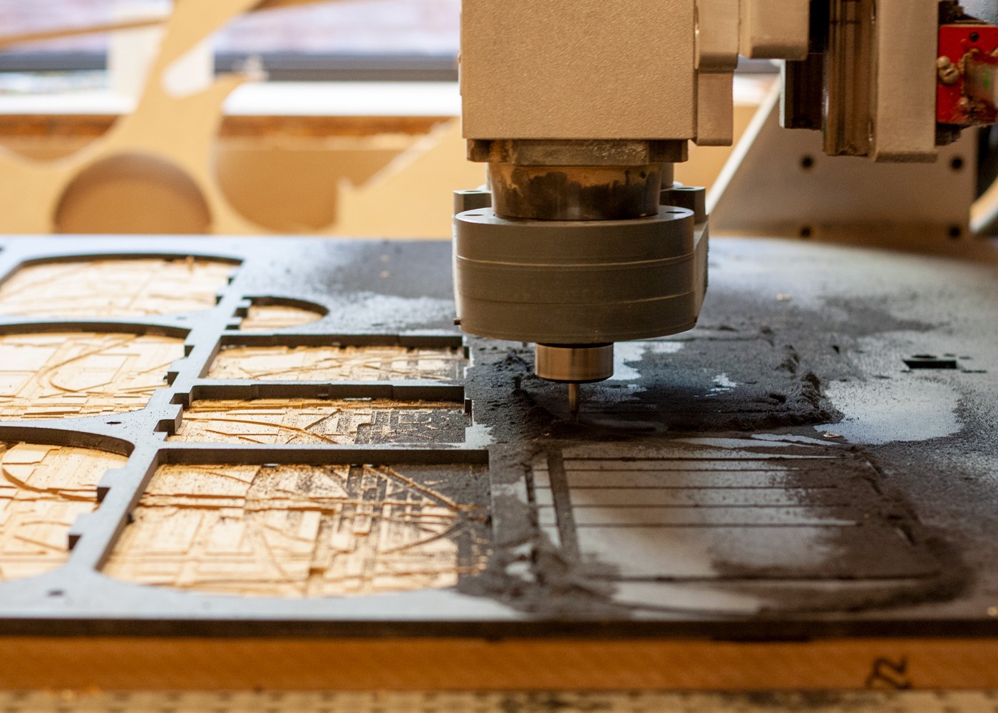
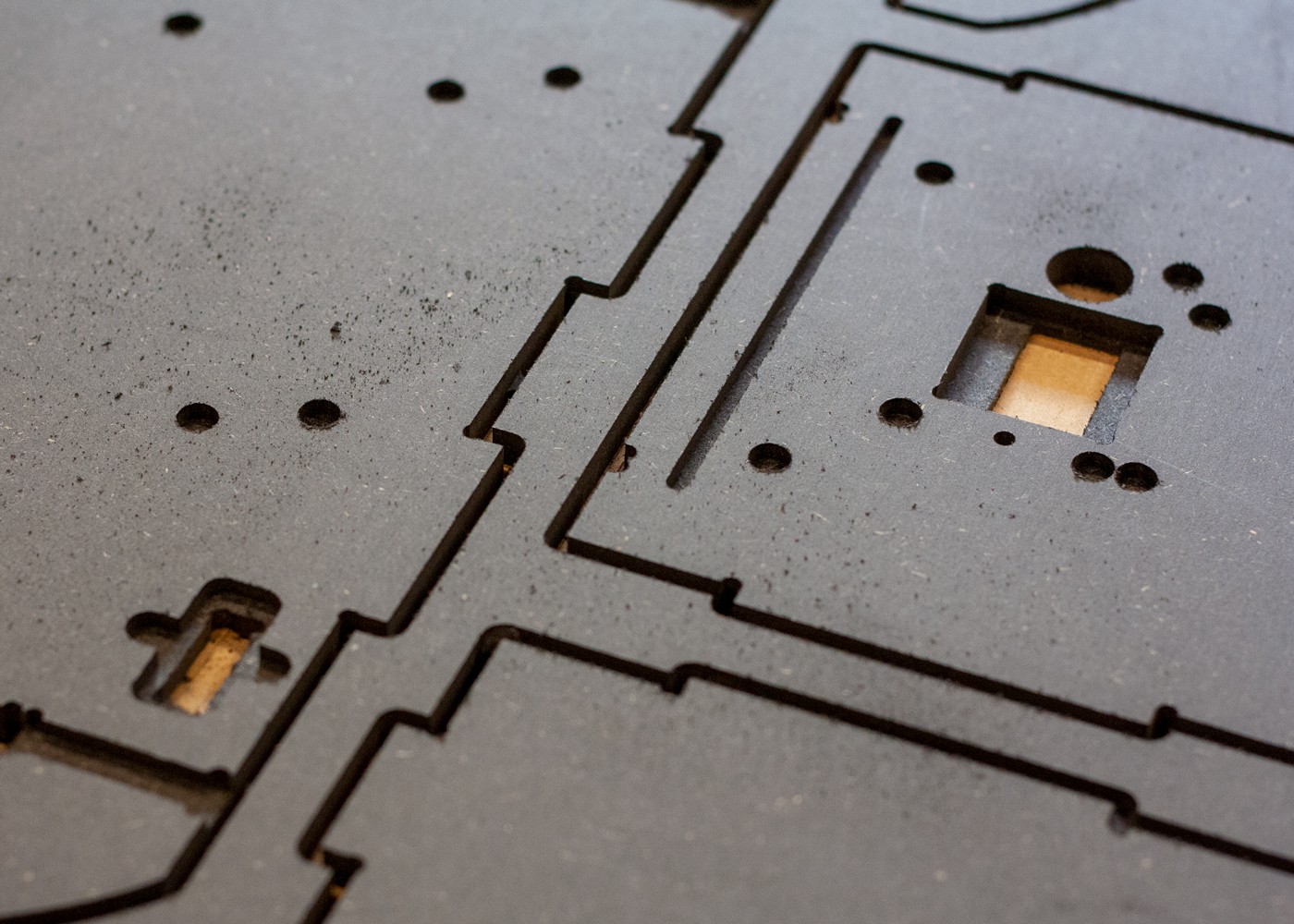
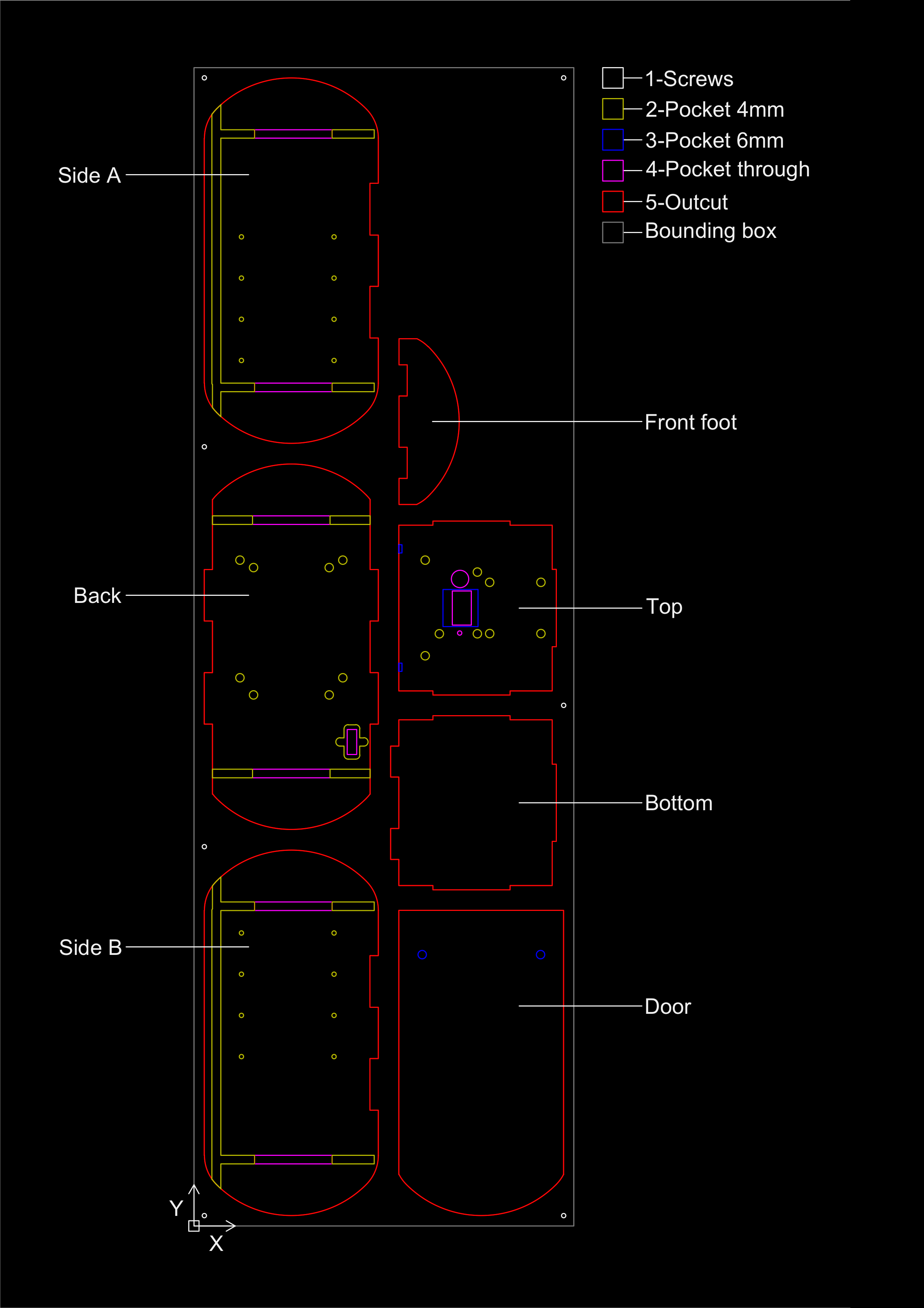
This design has been made to be CNC-milled on an 8mm thick board. We use Valchromat but it can be any 8mm thick plywood or composite board. The fabricated pieces are flat-packable and slot together without the need for screws or glues. The file has a tolerance of 0.1 mm. Beware, there are no T-bones / Dog bones yet, they are to be generated in the CAM, depending on the diameter of the bit you use. We recommand to use a 4mm flat mill for a better render.
![]()
![]()
Here is a preview of the cut file of the enclosure including all the parts and its strategy. The bounding box has a size of 369 mm x 1125 mm.![]()
-
6Laser cutting the technical panel and the shelves
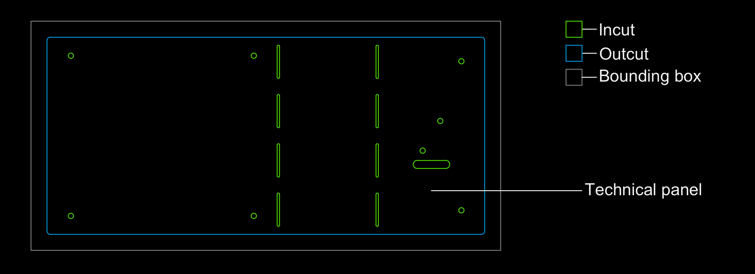
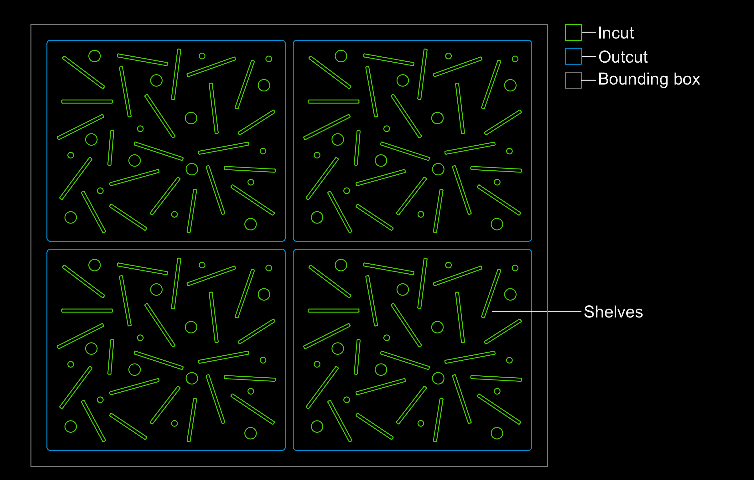
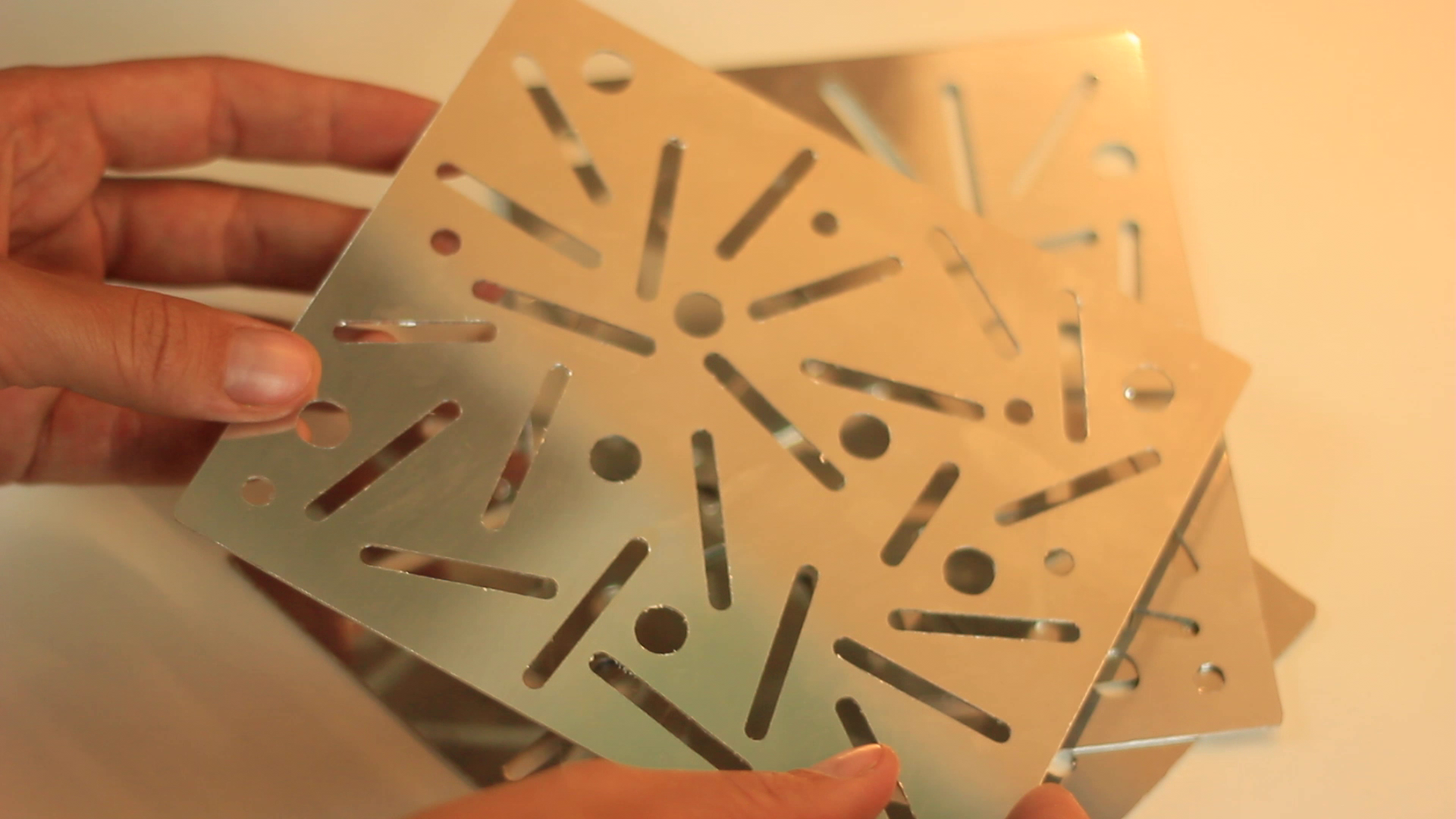
The technical panel and the shelves are made of 0.5mm and 1mm stainless steel respectively. However, they can be cut in any other material of your preference. The only constraint is that the technical panel has been designed to be folded with the cut lines drawn.
Here is a preview of the cut file of the technical panel. The bounding box has a size of 293 mm x 143 mm.
![]()
Here is a preview of the cut file of the shelves. The bounding box has a size of 323 mm x 276,5 mm.
![]()
![]()
-
73D printing of fasteners
These small parts have been designed to complement the fixing system of the different electronic elements, technical panels and door. They are :
- 17 x M3 nut inserts to be placed in the round pockets of the CNC-milled parts “Back” and “Top”
- 16 x M3 spacers (2x 30mm; 4x 15mm; 3x 10mm; 7x 5mm) to mount the various electronic components and the technical panel
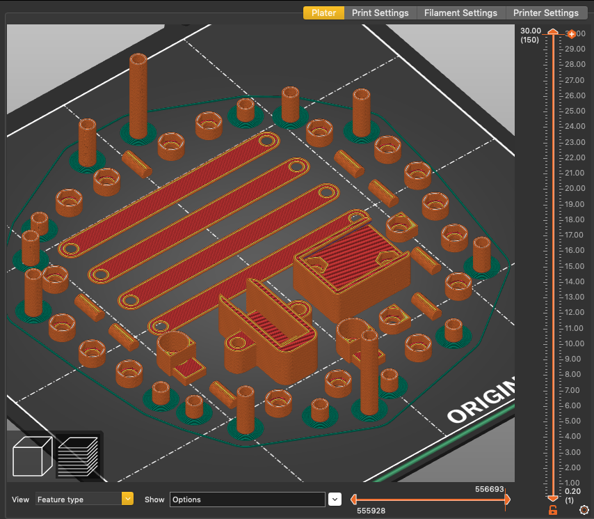
- 4x straps to hold the heating pad
- 1x holder to hang the power
- 1x holder to hang the sensor
- 2x holders to insert the magnets for the door opening system
- 8x dowels to support the four shelves
Here is a preview of all the 3D printed parts. Note that you can generate a brim only for specific parts, here the spacers.![]()
-
8Assembling the fermenter
Now that you have fabricated each element of the fermenter, it is time to assemble it! Below you will find the assembly strategy. Gather the different elements and bring your Allen key and the bolts and nuts referred to above. Please also refer to the CNC cutting file for the names of the different parts of the enclosure.
First, prepare and place the inserts and magnets
- Push a nut into each 3D printed insert, there are seventeen in total.
- Insert a dot of white glue into the seventeen 4mm pockets on the ‘back’ and ‘top’ parts.
- Then push the inserts into these pockets, with the visible part of the nut facing downwards. In other words, the nut is not visible once it is in place.
- Repeat this action for the two power inserts that are to be inserted into the two ears of the power pocket on the ‘back’ part.
- Next, insert two dots of white glue into the two 6mm pockets on the ‘top’ part.
- Take the two 3D printed magnet holders and insert the square part into the pocket, the protruding part towards the inside.
- Then insert the magnets into them, paying attention to the orientation of the poles.
- And finally, insert the two other magnets into the two 8mm pockets of the ‘door’ part paying attention to aligning the poles.
Second, attach the fan to the “top” part of the enclosure
- Lay the ‘top’ part flat on your work surface with the slots and pockets facing upwards
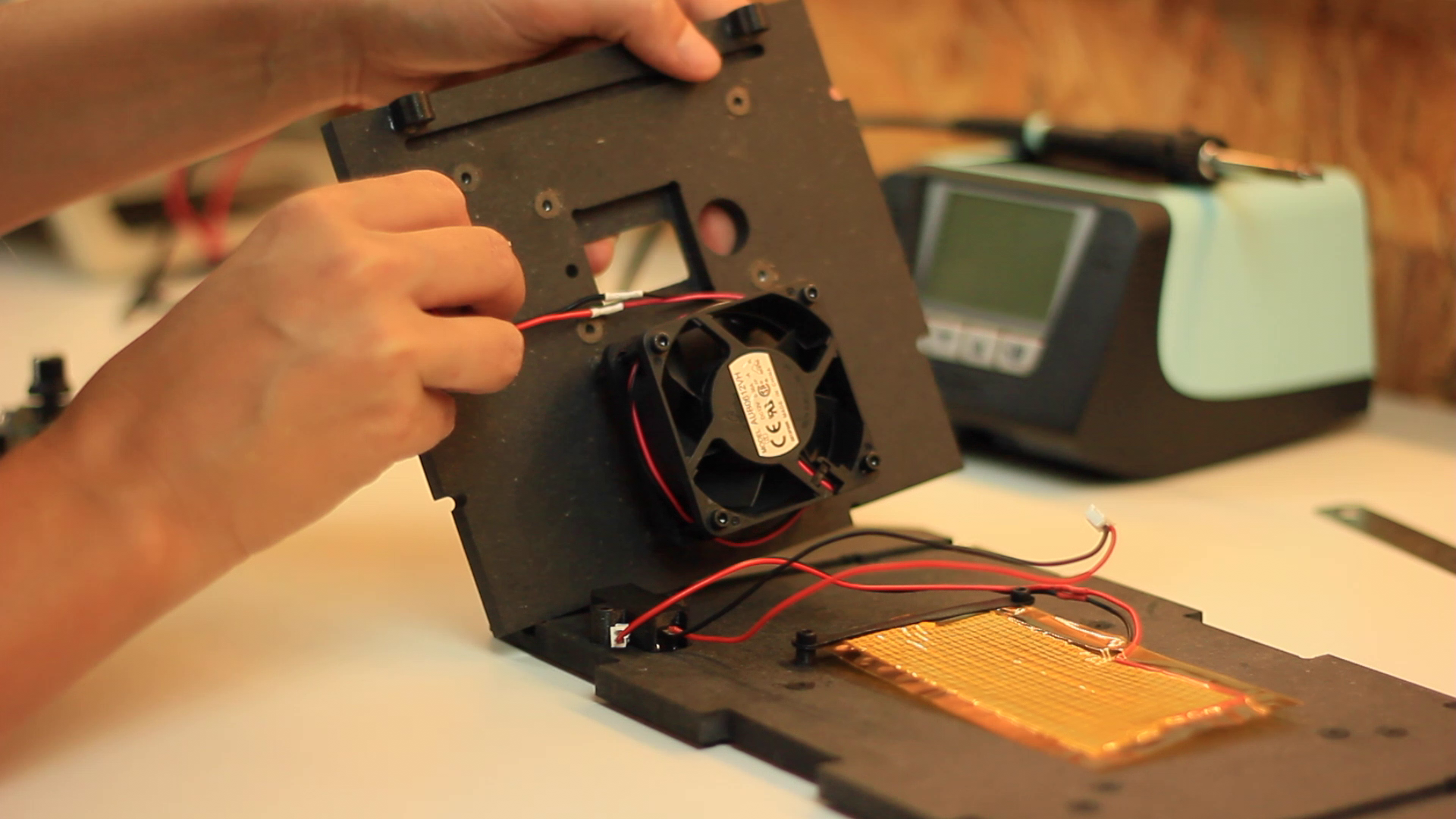
Place four 40 mm bolts with four 10 mm spacers on the Fan. Screw the PCB into its nuts inside the ‘top’ part.
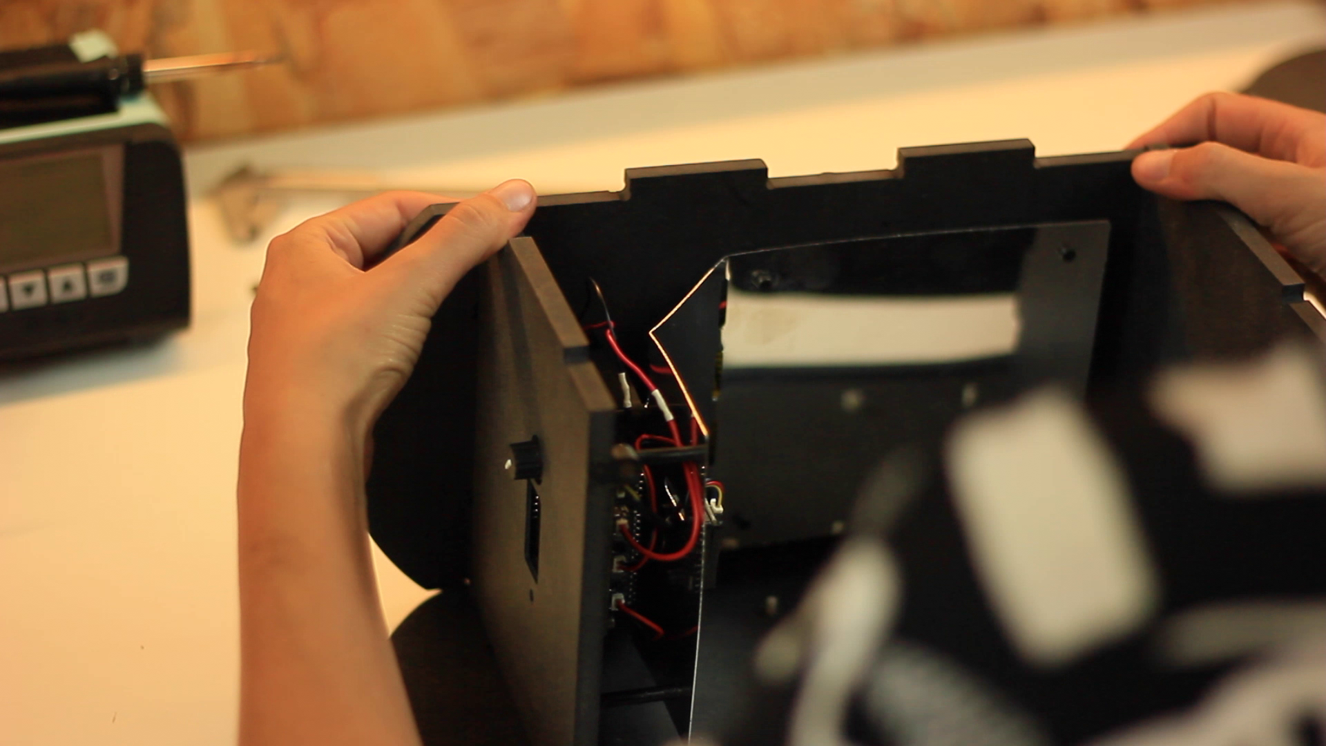
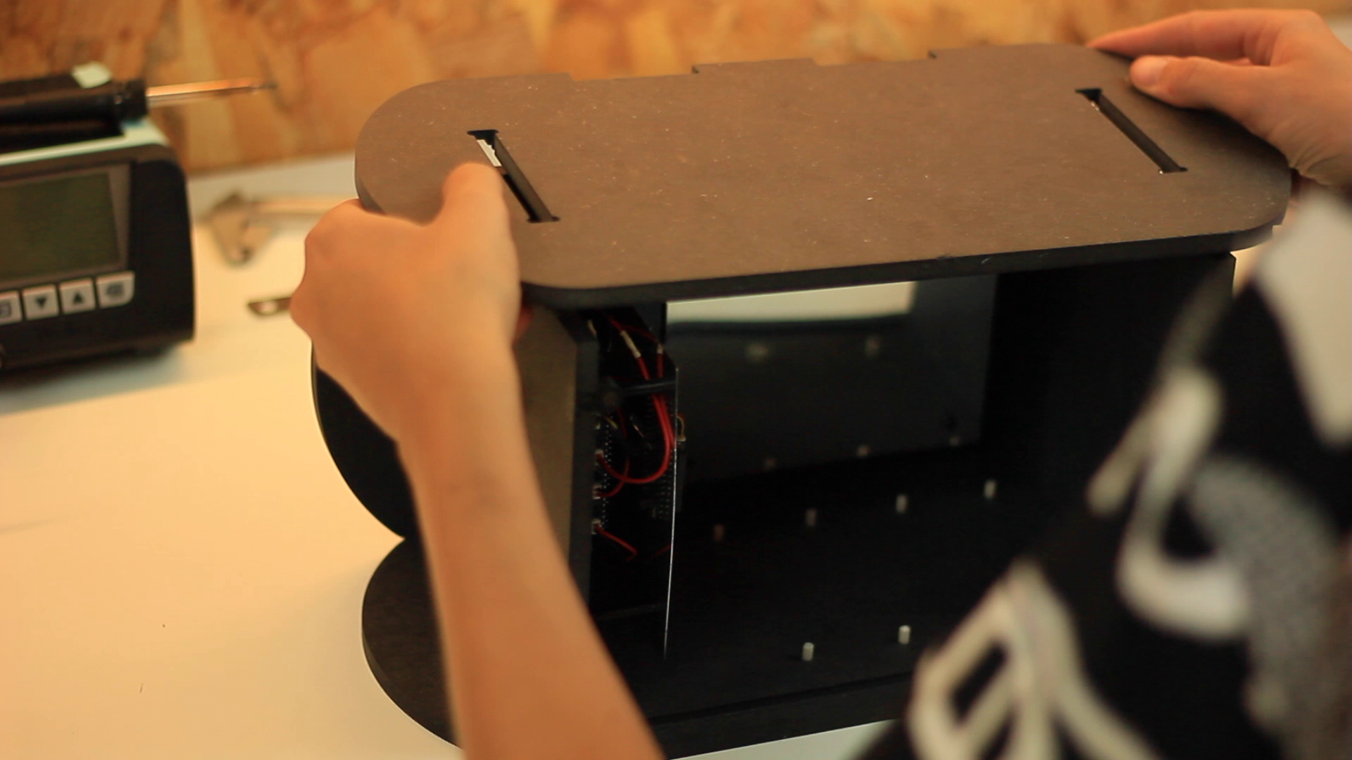
Thirdly, insert the “back” part into the “top” part and attach the PCB
- Lay the ‘back’ part flat on your work surface. Insert the top part into the top slot. Make sure it is aligned correctly before pushing to the end.
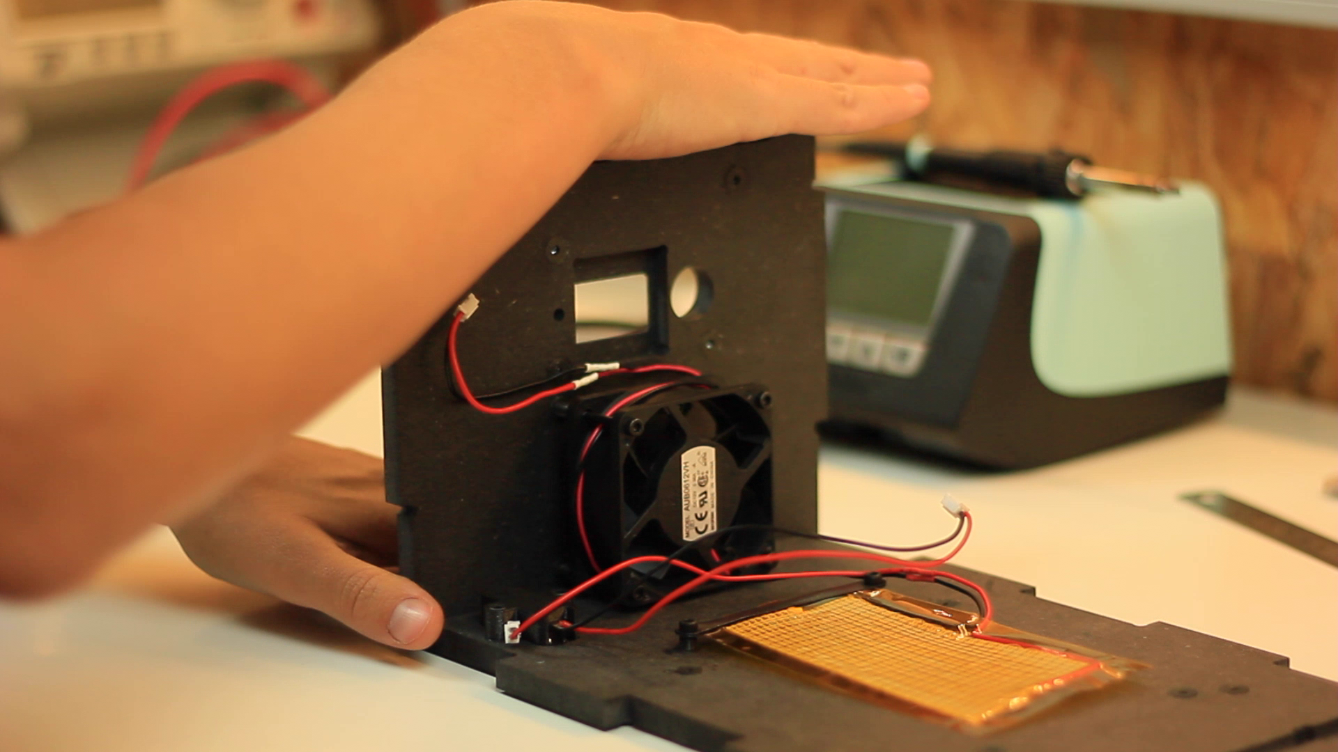
- Place three 15 mm bolts with three 10 mm spacers on the PCB. Screw the PCB into its nuts inside the top part, inserting the knob and screen into their holes.
- Connect the fan to the PCB (air).
Fourthly, attach the heating pad to the “back” part and insert the “bottom” part
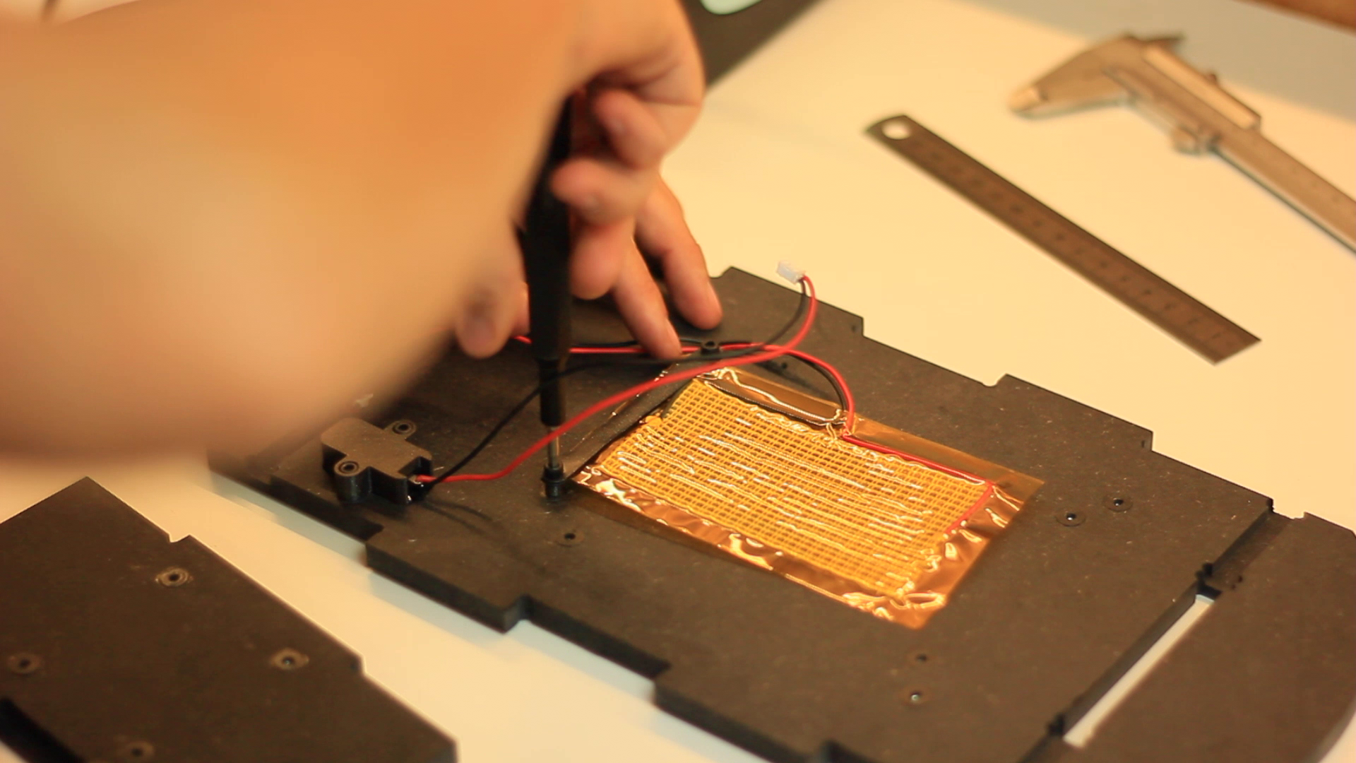
- Prepare two sets of 2 x 10mm bolts with 2 x heating pad holders and 2 x 5mm spacers. Screw the two sets on the inner inserts of the ‘back’ part. Before tightening, place the heating pad between the heating pad holders.
- Connect the heating pad to the PCB (heat).
- Insert the ‘bottom’ part into the bottom slot. Make sure it is aligned correctly before pushing to the end.
Fifthly, attach the power
- Turn your unit 90°. Insert the power button inside the power holder and screw it into the inner slot of the back part with two 10mm bolts. Connect the power button to the PCB (power).
Sixthly, attach the sensor and the technical panel
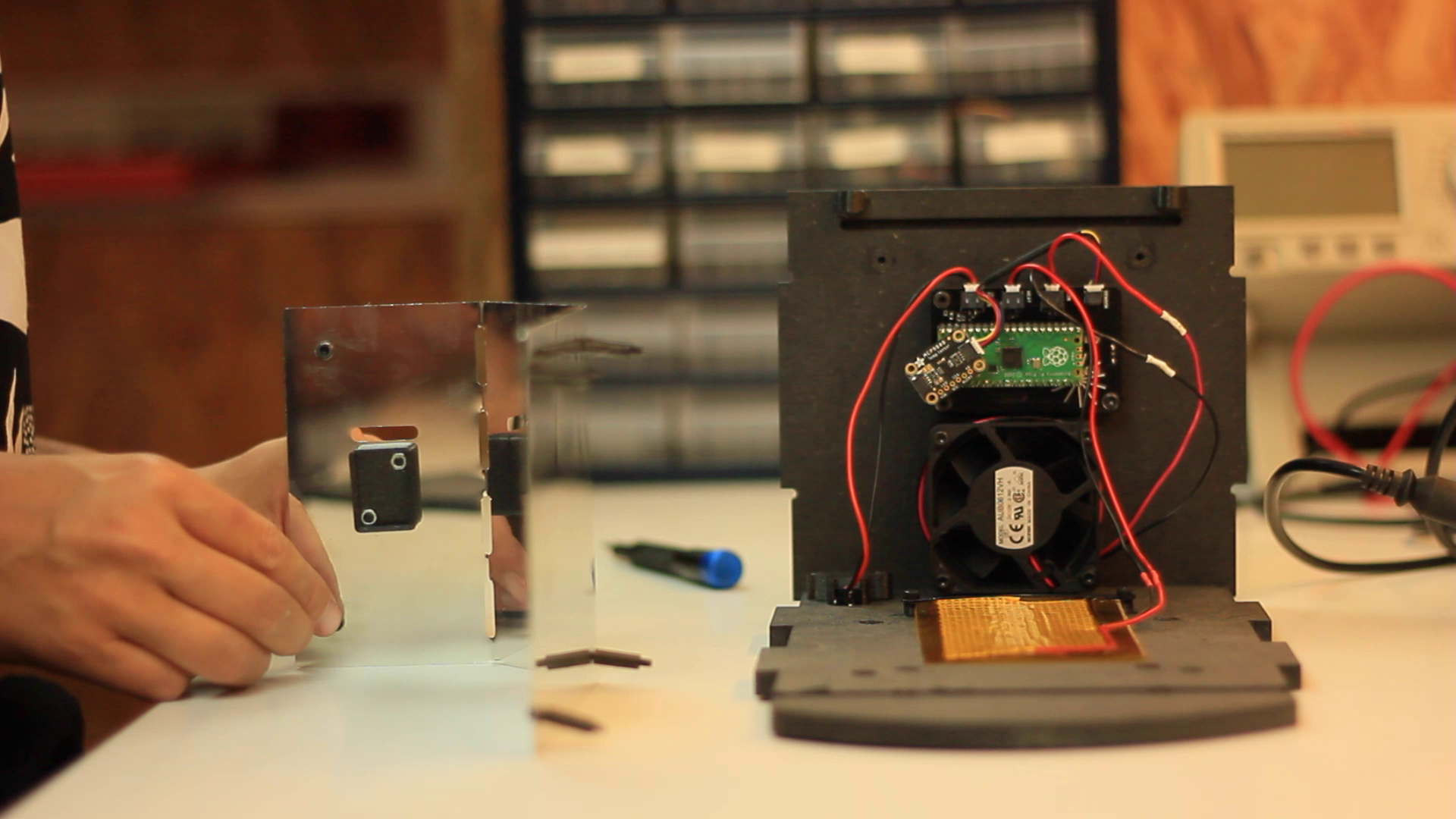
- Screw the sensor holder to the technical panel with 2 x 10 mm bolts.
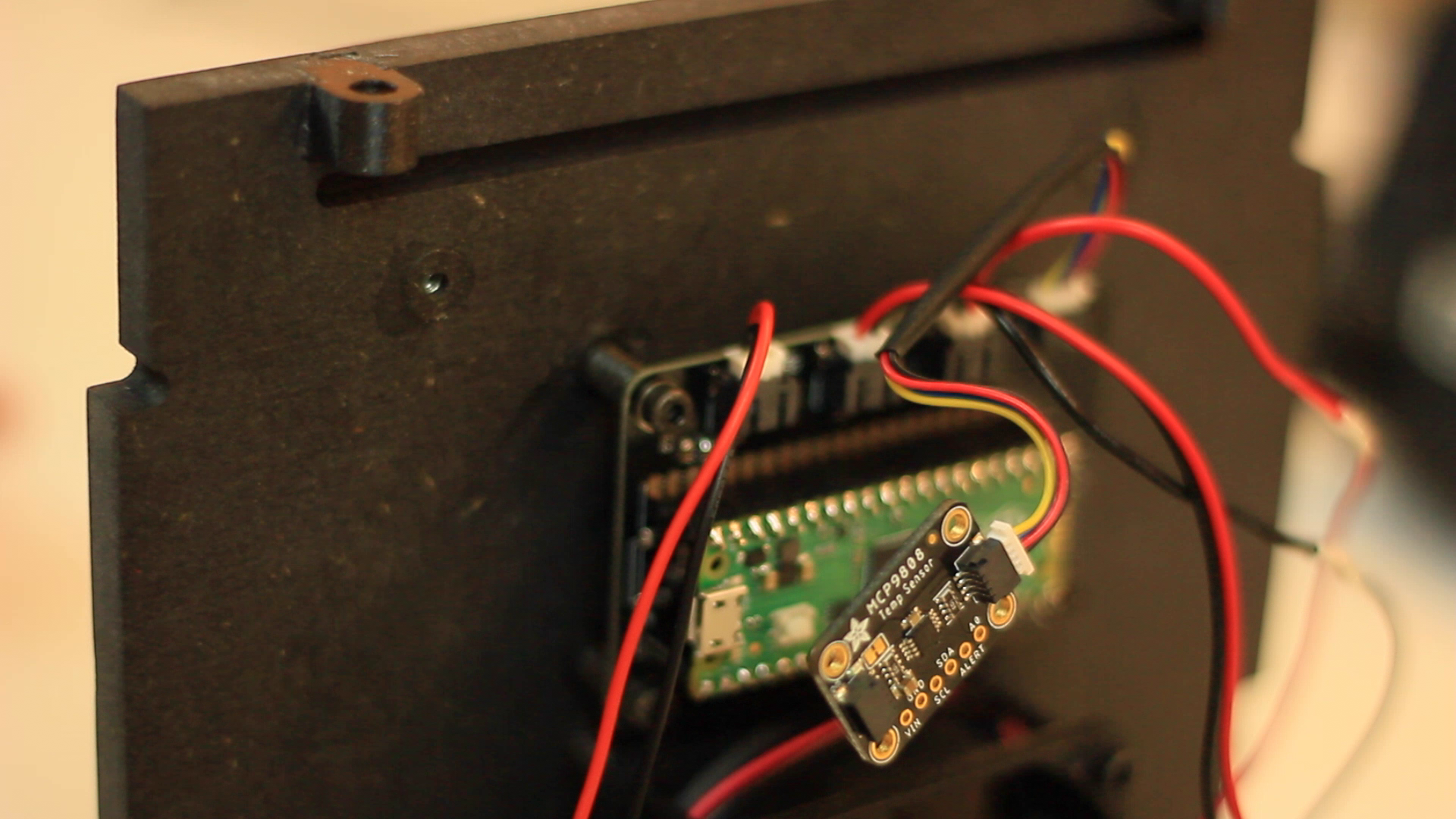
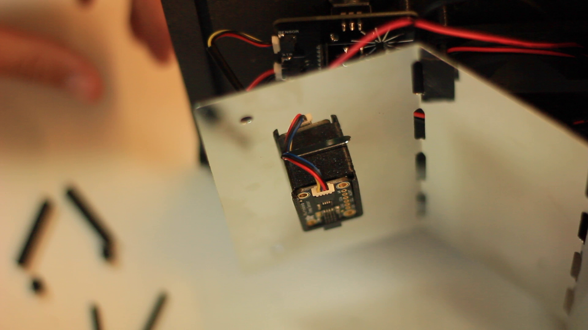
- Connect the sensor to the PCB (sensor). Insert the sensor through the slot in the technical panel and slide it into the sensor holder.
- Screw the technical panel to the ‘top’ part with 2 x 40 mm bolts and 2 x 35 mm spacers. As well as to the ‘back’ part with 4 x 20 mm bolts and 4 x 15 mm spacers.
Finally, close the enclosure with the sides, the front foot and the door
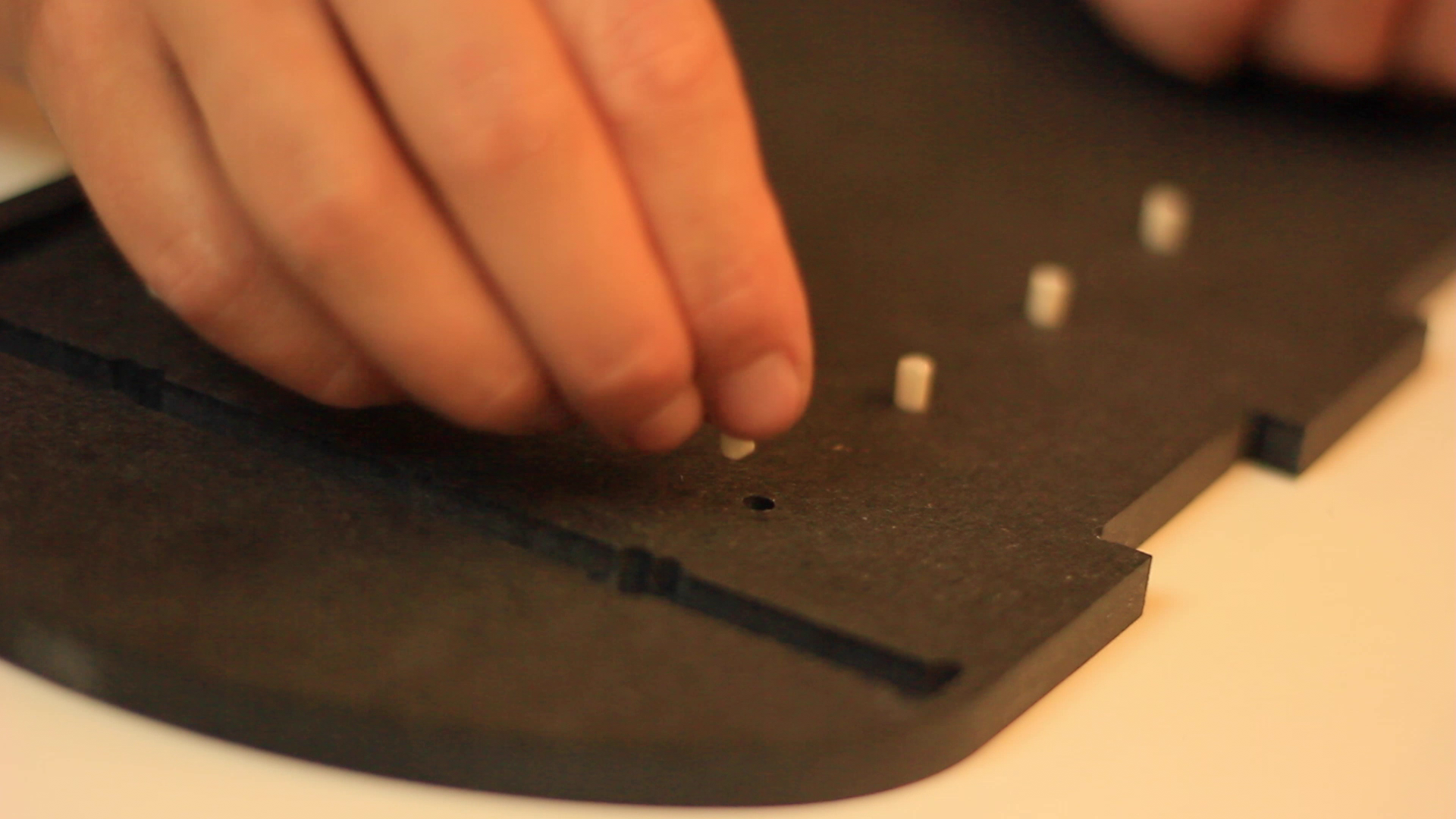
- Inserts the dowels in all the holes of ‘side A’ and ‘side B’ parts
- Insert the unit inside the ‘side A’ part into the slots. Make sure it is aligned correctly before pushing to the end.
- Insert the unit inside the ‘side B’ part into the slots. Make sure it is aligned correctly before pushing to the end.
- Insert the front foot from the bottom
- Insert the door from the top
Notes
- If the bolt turns loosely, reduce the size of the spacer by cutting 1 mm off one end with a cutter.
![]()
![]()
![]()
![]()
![]()
![]()
![]()
![]()
![]()
An open-source fermenter
A device to promote plant-based protein and open-source tools so that everyone can make them at home for the benefit of our planet
 Maud Bausier
Discussions
Become a Hackaday.io Member
Create an account to leave a comment. Already have an account? Log In.