-
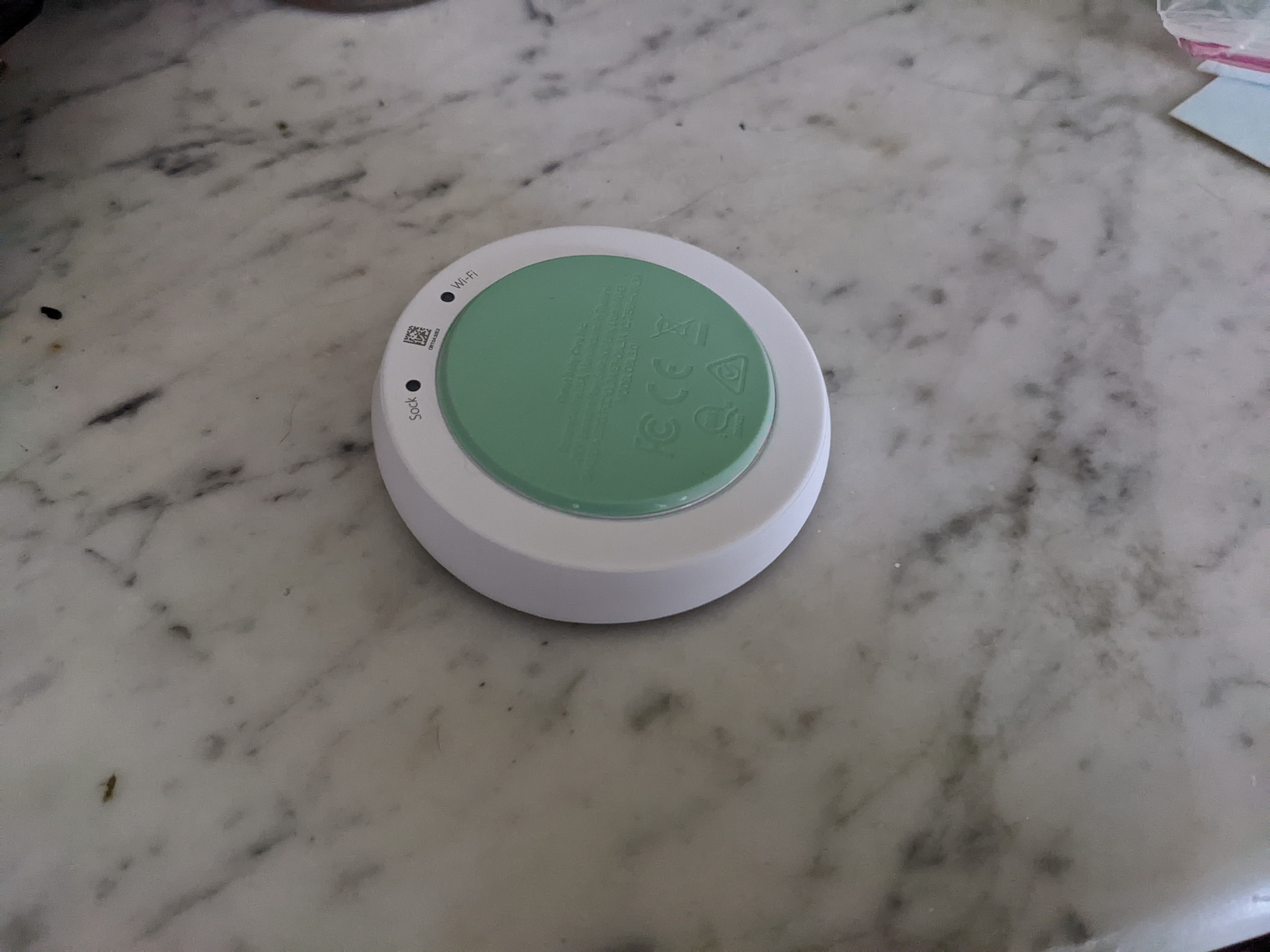
1Remove the pad on the back that hides the screws
The green pad on the back hide the screws that hold the base station together.
![]()
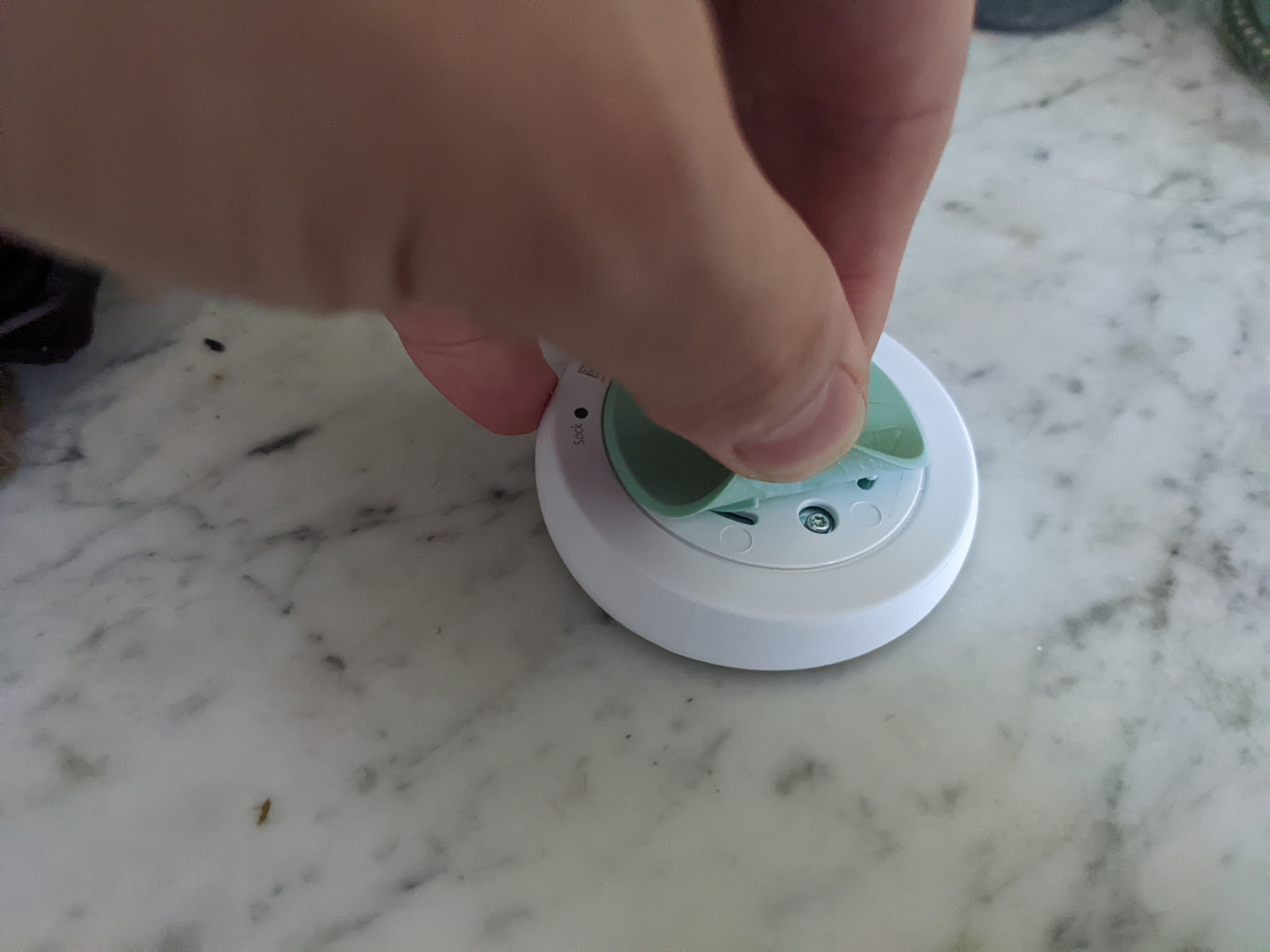
It was surprisingly easy to remove with just my finger nails by slowly lifting each edge in a circular motion until the whole pad came off
![]()
-
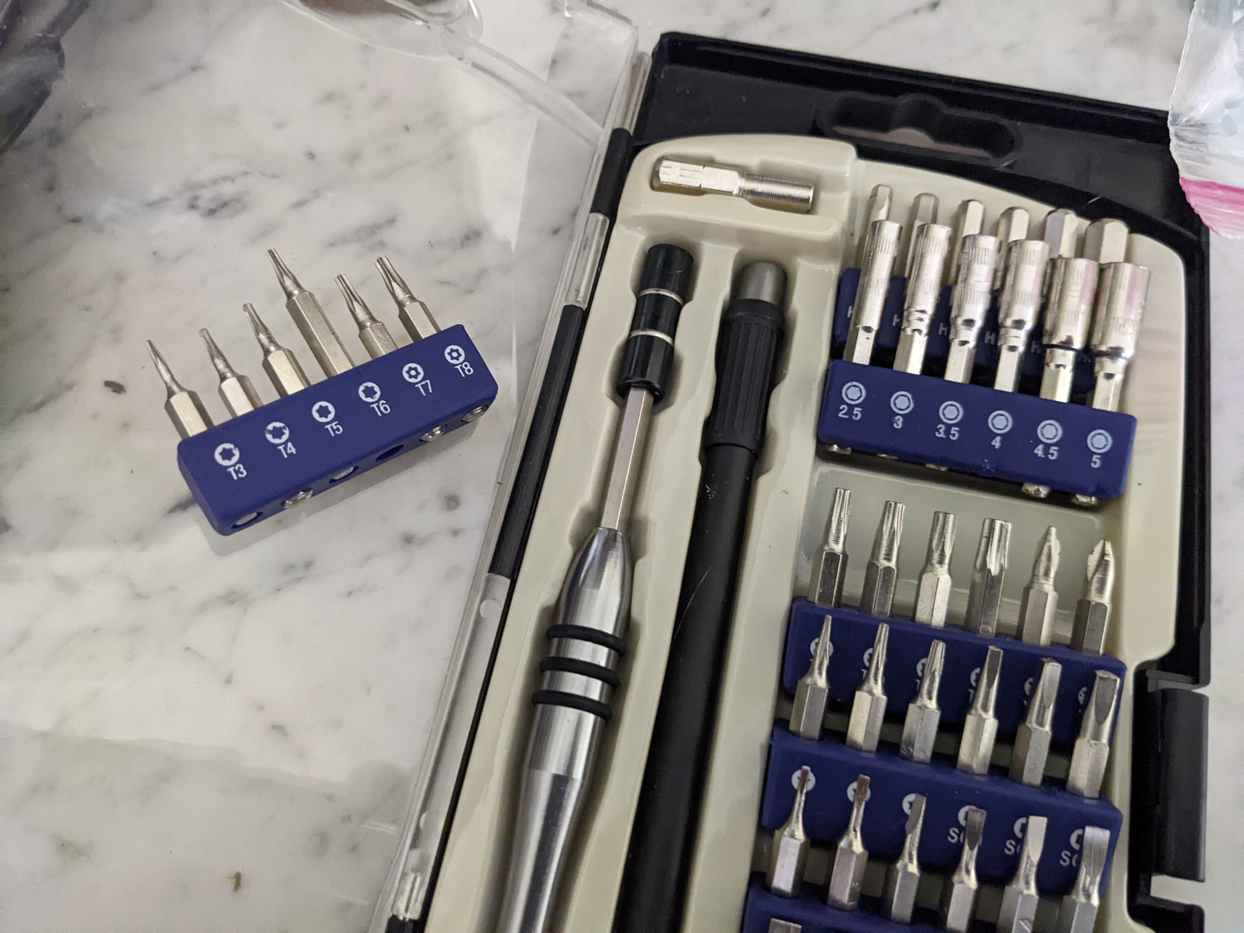
2Remove the four screws to disassemble the base station
The screws require a T6 "security bit" Torx driver. These can be found in most electronics fix it kits
![]()
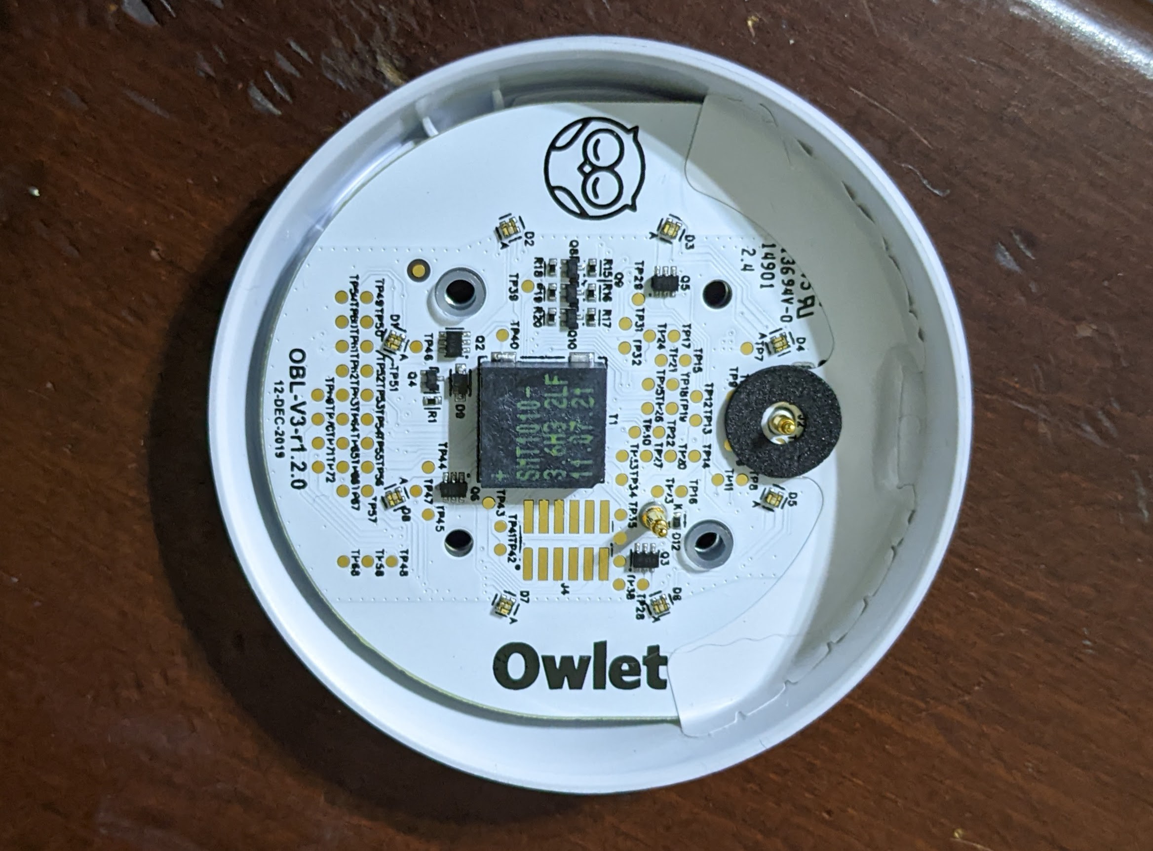
Removing the screws on the bottom allows you to remove the top cover
![]()
-
3Understanding how to disconnect the speaker
moThe big black device in the middle of the printed circuit board (PCB) is the speaker (aka buzzer, or transducer). You can see a little slit in the one side where the sound comes out.
There is a back side to the circuit board that you cannot easily see since the board is taped in place. If you'd like to see the backside of the board, see the photos in the FCC application
The white sticker on top of the speaker was placed after the PCB was manufactured as a product ID for the PCB. By removing the speaker, you can see the identification markings on the speaker.
![]()
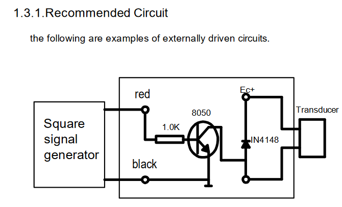
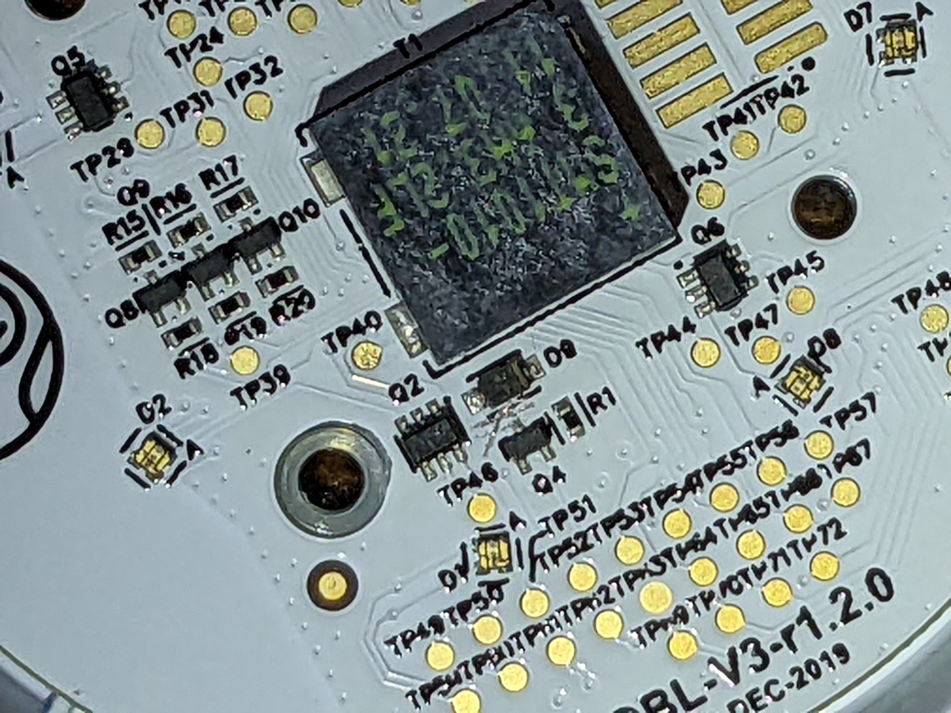
The speaker is a "SMT1010-3.6H3.2 LF" by BeStar Acoustic. From the datasheet we can see that only two of the four solder legs do anything: the one by the (+) sign, and the one across from it (the two legs on the left of the photo above). The datasheet also shows the example circuit for the speaker.
![]()
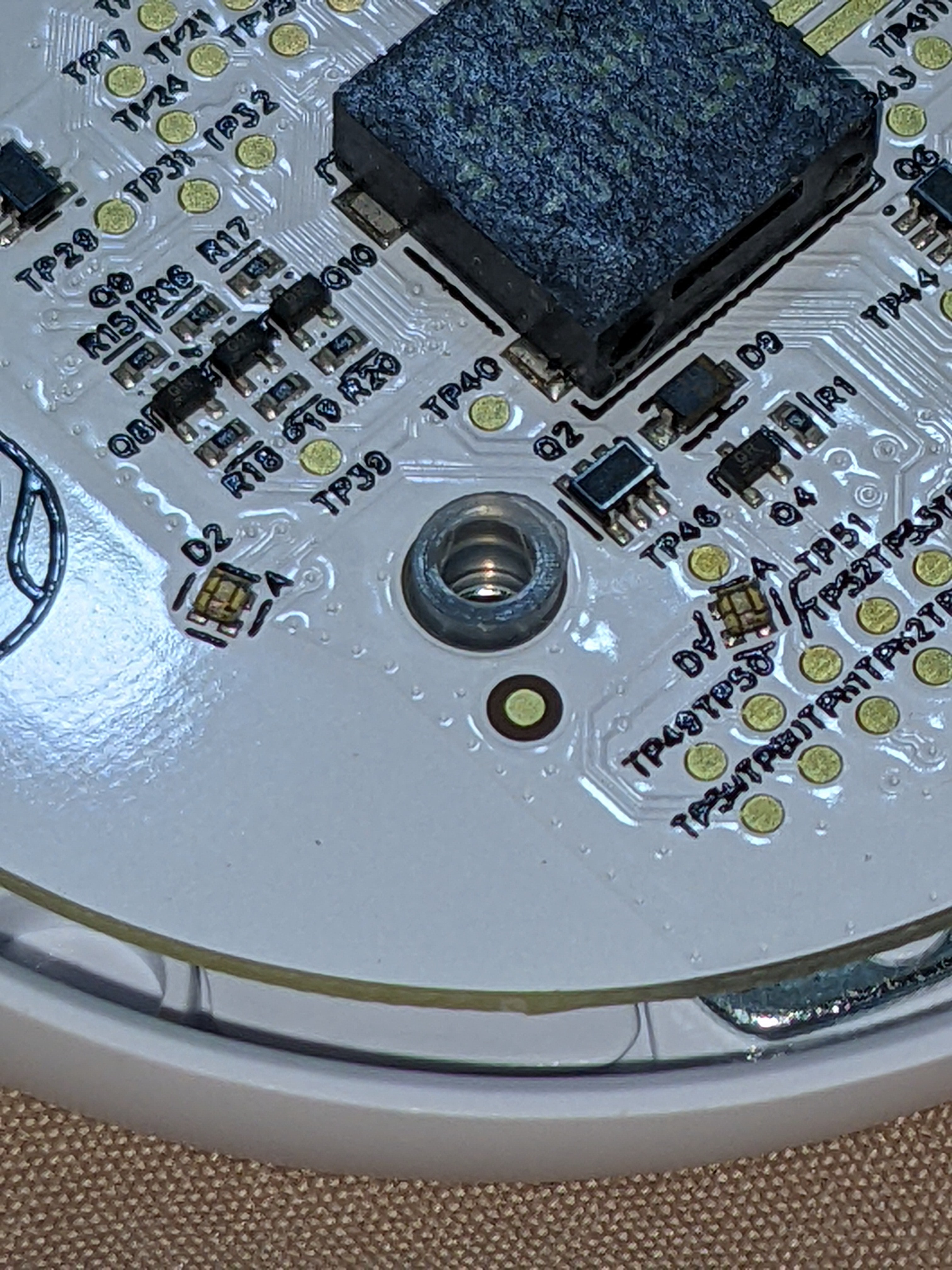
Zooming in, we can see the transistor (Q4), the diode (D8), and the resistor (R1) that are part of the circuit that drives the speaker. A simple explanation of this circuit is that something (the main processor on the base station) generates a sound wave signal that activates the base of the transistor and allows power to flow from "Ec+" through the transducer, through the transistor (from collector to emitter), and then to ground.
![]()
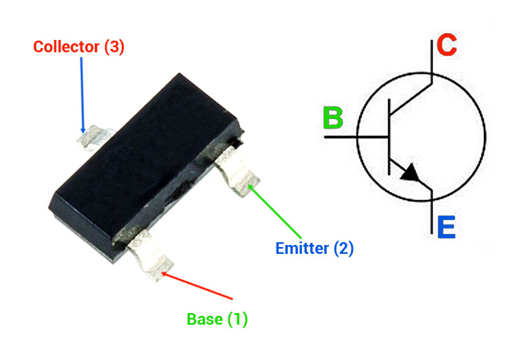
On three leg transistor chips like this, the single leg on the top is the collector.
![]()
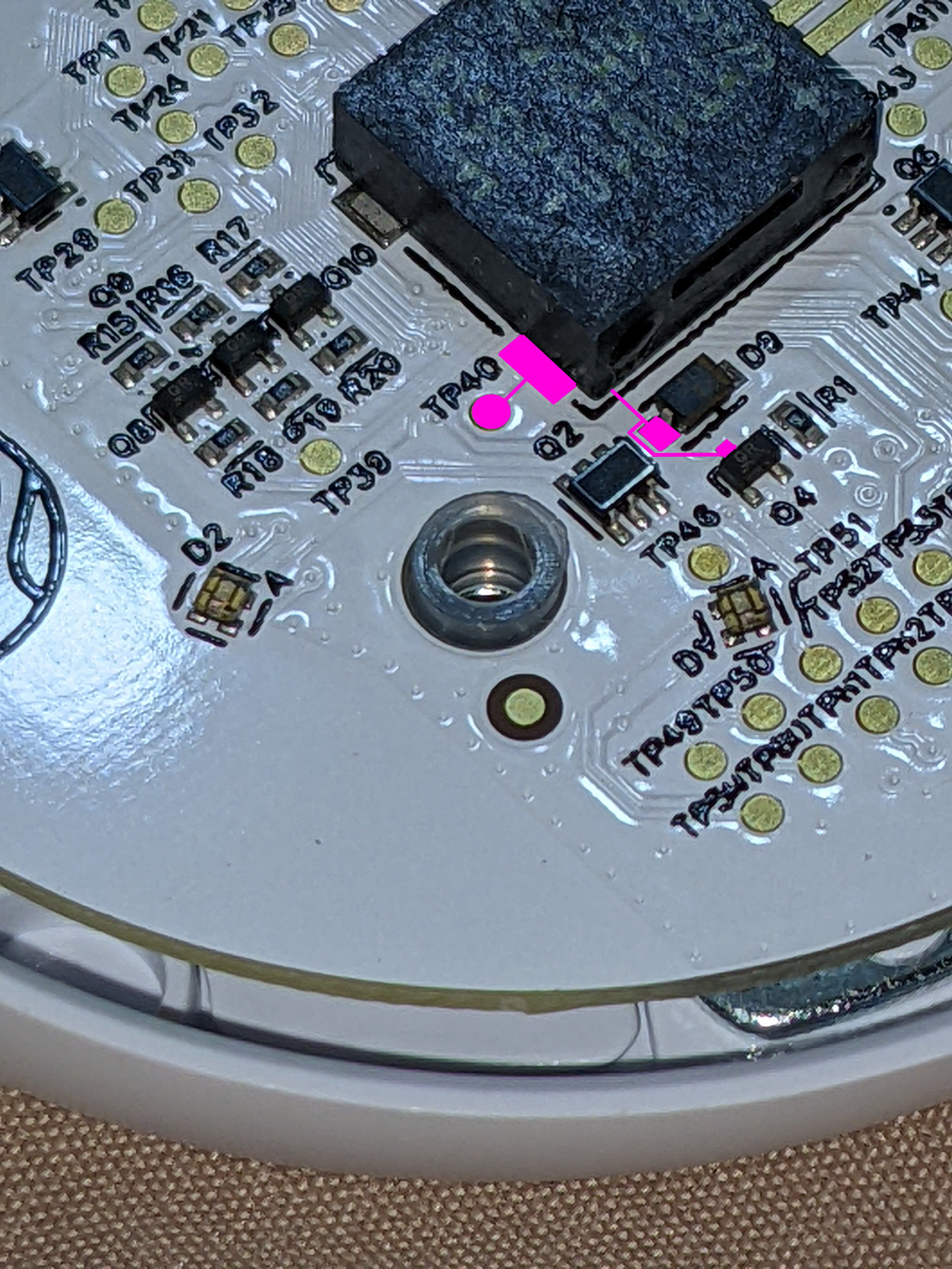
in the figure below, I tried to highlight the trances from the transistor to the speaker, diode, and "test point". The easiest way to cut off the speaker from the driver will be to cut the trace from the collector to the diode.
![]()
-
4Disconnect the speaker
Use an X-Acto knife or a sharp box cutter blade to cut the trace (wire on the PCB) from the collector to the diode. This will disconnect the speaker from the driver. You only need to cut through the thin copper trace on the top of the PCB (hidden under the white top coat of non-conductive paint). See the score/cut marks on the photo below. You can confirm that the trace/wire has been cut using a continuity tester on any multi-meter.
![]()
-
5Test and reassemble
Before reassembling, you can double check the speaker is disconnected by plugging the base station into the USB charger. Without the sock attached (or worn) it should alarm after about 60 seconds. The lights should change to the alarm mode, but the base station should no longer make a sound.
Reassemble the same way you took it apart. The pad on the base station should still have enough adhesive that you can re-stick it.
-
6Disable notification sounds on your phone
On Android, wait for an alarm to occur on your phone, then long press the notification and go to settings. Then tap each of the alarm bells on the left to silence each type of notification.
![]()


Discussions
Become a Hackaday.io Member
Create an account to leave a comment. Already have an account? Log In.
Thank you very much sir for your time to make this step by step tutorial! It was so detailed and it worked perfectly! You're a lifesaver, it was driving me nuts and the support is just awful to help! Best regrads from Greece!
Are you sure? yes | no