Enzo Lombardi
-
Adapter PCB with IMU delivered
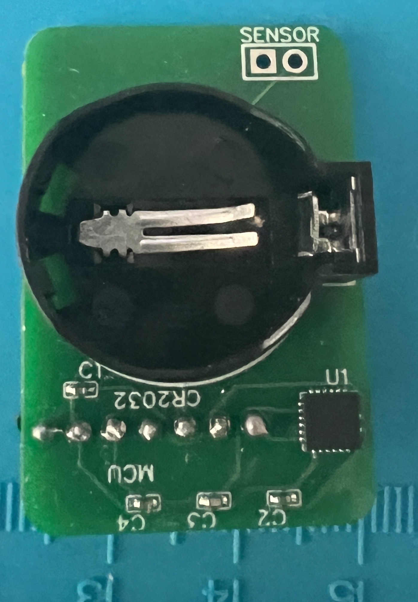
12/29/2022 at 20:08 • 0 commentsI got the PCB back from PCBWay through their sponsorship program and it looks great:
![]()
In the picture the IMU (bottom right) and the sensor pads (bottom left) are clearly visible.
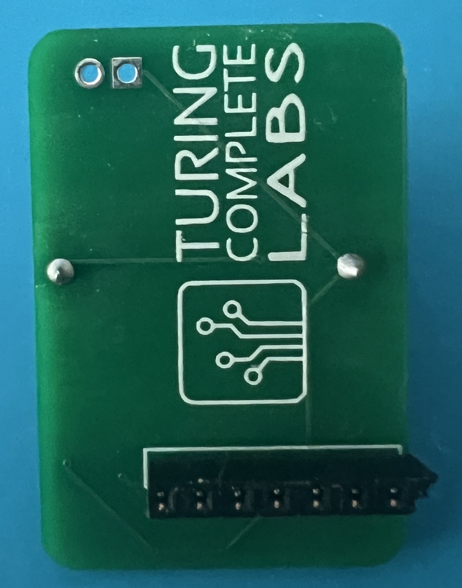
And of course, big center stage for the CR2032 battery holder.Fabrication quality is impressive, a quick test showed the MCU readings being accurate. In retrospect I should have use both sides of the MCU pins instead of just one, but I soldered a socket, that should work:
![]()
I will use the remainder of this vacation time to bring the project to completion and present it to an audience of coworkers interested in learning about "Arduino" things. What's remaining?
- actually putting it together, trivial
- power code; for the advertising part it's done. I will need to code a way to wake up the MCU when the sensor triggers, still haven't figured out - from consumption perspective - what's a reasonable choice
- BLE API. The MCU is powerful enough to store multiple "profiles". Each user can have the "mileage" stored on the MCU and it would be a matter of providing a "switch-user" write characteristic, which seems... logical. Real time measurements of speed and incline are user independent. So... trivial.
- Display: an app on the phone? a separate device? a more sophisticated app that generates a random scenery based on speed an slope? an even more sophisticated app that can simulate the most famous marathon playfields?
Suggestions?
Stay tuna!
-
Sugru
09/01/2022 at 17:07 • 0 commentsStill working on a good support for the sensor, but I decided that if I wanted to close the treadmill and make it usable for the time being, I had to compromise on using Sugru. For now.
-
Reading the slope using the MPU
08/24/2022 at 01:43 • 0 commentsToday I spent some time with a trivial task. When you forget to call Wire.begin() bad things happen when you try to use I2C.
Anyway, the code now reads the Y acceleration from the MPU and I built a table of slope % as function of Y-accel.
The LCD display was helpful in this and I am glad it worked. Now it's time to build a BLE service around this and start publishing values.
Code in github is up to date.
-
First Github drop
08/22/2022 at 15:56 • 0 commentsHere be the source code!
Next steps: after being happy with the small Xiao BLE for the initial prototype phase (will it work? Of course!), I decided to use the Adafruit nrf528xx feather because of:
- I already have a couple of LCD feathers. It will make the power testing much easier than a power hungry OLED display
- I already have a bunch of IMU feather. I knew at one point these would turn useful, so I plan to stack both the display and the IMU, connect a battery and call it a day.
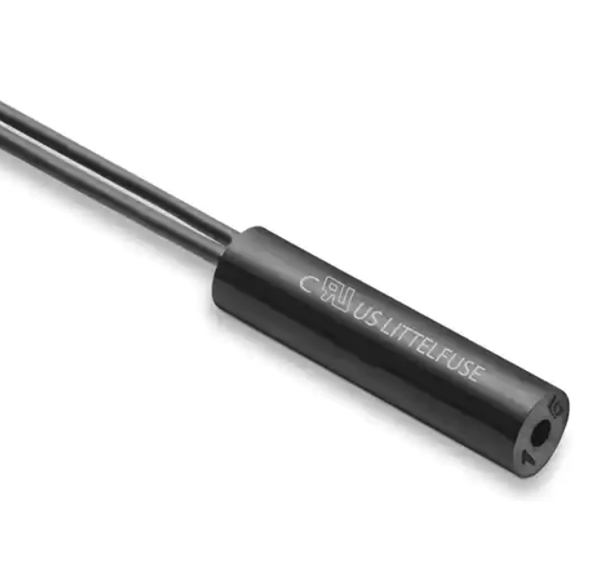
- Last but not least. At maximum speed, the RPM reading doesn't seem consistent. I doubt it's the Reed switch (more likely is the treadmill board to be inaccurate due to the lack of feedback), but in order to have a reference part number I also ordered a bunch of these Reed switches:
![]()
Stay tuned.
-
Proof of concept
08/21/2022 at 04:38 • 0 commentsProof of concept.
It works. For now it displays a value that's a function of RPMs. Next step: BLE. -
Rewriting RPM computation logic
08/15/2022 at 18:44 • 0 commentsI am quite unhappy with the RPM computation logic as it seems to be prone to fluctuations.
So I decided to see what happens if I actually count the number of ticks happened in the last second and multiply for 60. Or whatever timespan it takes so I can multiply by 15. It seemed too complicated until it hit me: I can use a circular buffer to record all "ticks" timestamps and when I want to compute the RPMs go over the array and count the ones that are within the last second. Pseudo code:#define MAX_RPMS 3000 #define BUFFER_SIZE (MAX_RPMS / 15) uint64_t timestamps[BUFFER_SIZE] uint16_t index = 0; void tick() { timestamps[index] = millis(); ++index; index %= MAX_RPMS; } uint_16t getRPMs() { uint64_t cutoff = millis() - (60000/15); uint16_t result = 0; // can be optimized by going backward from index // but not worth here. for(int i=0; i < BUFFER_SIZE; i++) { if (timestamp[i] > cutoff) { ++result; } } // minor optimization. I couldn't resist return (result << 4) - result; }
This code has also the proper side effect of returning 0 if the last tick was over a second older vs. using a different timing mechanism to zero the result.
If this works in a satisfying manner, next step will be add some crude BLE code. -
RPM math
08/05/2022 at 18:02 • 0 commentsQuick math to determine the RPM range.
The pulley driving the belt has a diameter of 44mm.
That puts the number of RPMs at 10mph to a bit shy of 2000.
Which means that four digits are enough to accomodate the RPMs at unit precision.2000 RPMs is also 33.3 RPSs. Which gives a period of 30 milliseconds at maximum speed.
-
First cut at RPM calculation algorithm
08/05/2022 at 16:46 • 0 commentsSo the Reed Switch worked as expected, no brainer of course.
I put together some code to compute the RPMs and display them on the Seeeduino Extender OLED display. If I display the result in RPMs, the output seems to be reasonably right, but if I divide further the fluctuation is bigger. Time to debug.
Current code is here, I am suspecting something is wrong with the 5ms forced delay in the IRQ.
Adding BLE to a "dumb" treadmill
I have a Gold Gym 410 which is perfect for my purposes. But I always had an itch about tapping into speed and inclination data.