WJCarpenter
-
PCB 2nd iteration works
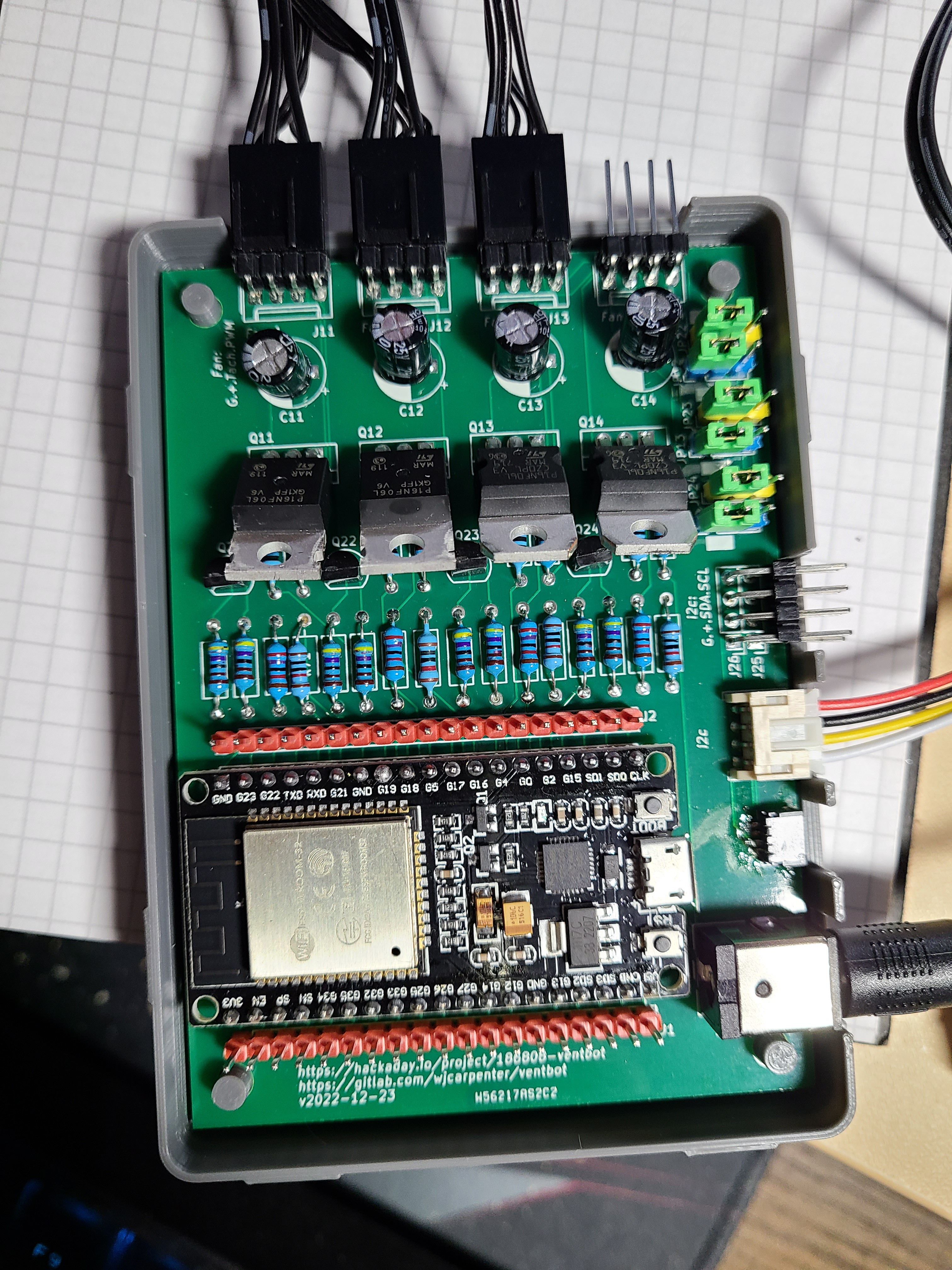
12/30/2022 at 23:08 • 0 commentsI received the shipment of revised PCBs from PCBWay a few days ago. I immediately populated one completely and tested it. I wanted to have one copy of the board that populated everything, including things that I don't plan to actually use myself. I'm pretty pleased with the little tweaks in the revised layout. And, it works! Here's a picture of it resting on a 3D-printed enclosure base. (I'm still fine-tuning the enclosure.)
![]()
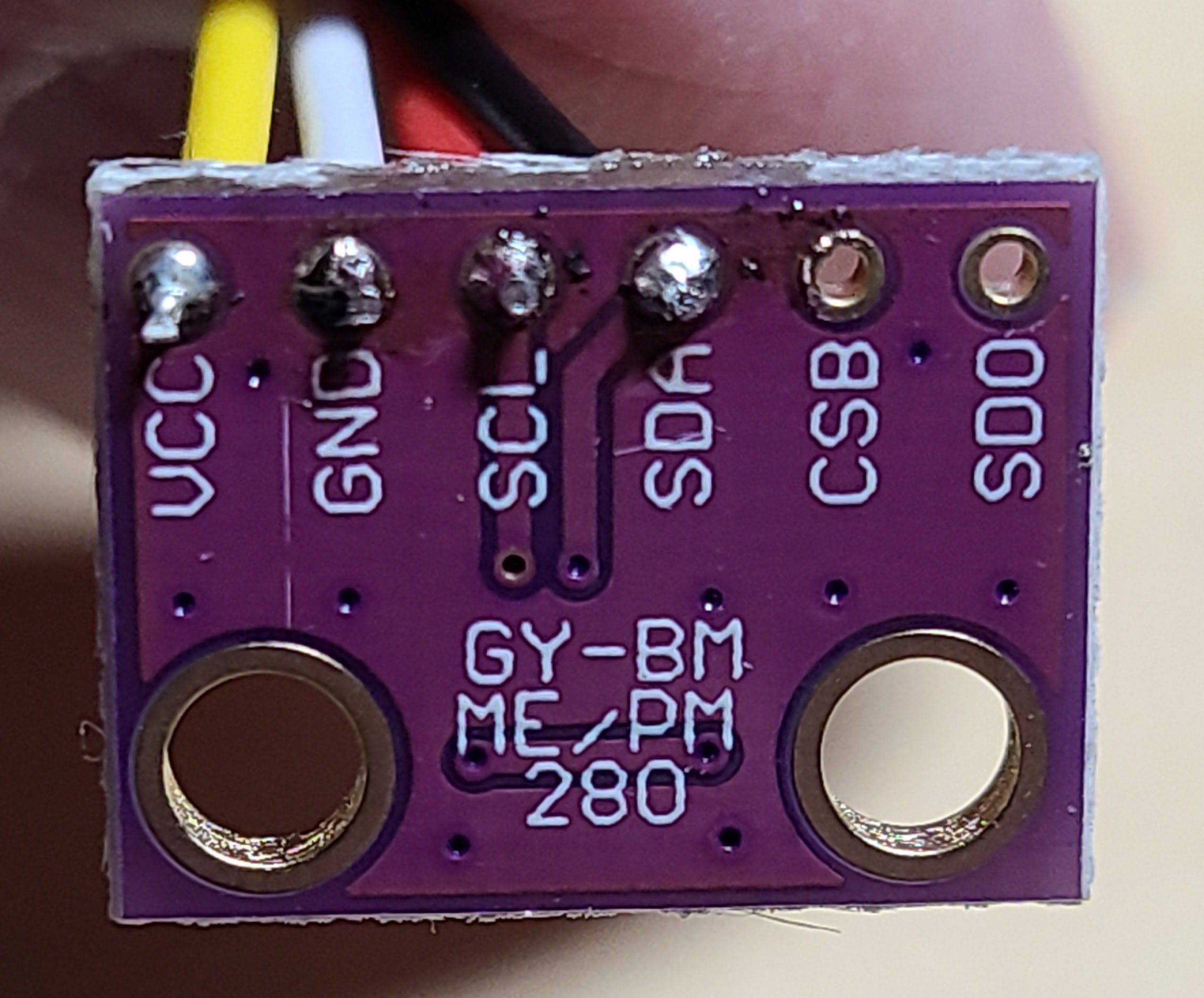
I noticed one blunder that was also present in the first revision. The JST-SH and JST-PH connectors use the same order for the wires for I2C. I didn't notice that JST-PH connector was flipped over from what I was assuming. This is completely my mistake. Once I noticed it, the Adafruit article was clear enough. I just wasn't paying attention. Consequently, this PCB is not directly compatible with Adafruit STEMMA devices. For myself, that's not a huge deal since I am wiring up generic BMP280 breakout boards and soldering the wires from the JST-PH cable directly to the boards. I just had to ignore the wire colors (which were not applicable anyhow) and pay attention to the signal order from the board. In the generic JST-PH cables that I have, pin 1 is red, pin 2 is black, pin 3 is yellow, and pin 4 is white.
![]()
If I ever revise this design, it will be easy to correct this. If you use a "vertical insertion" JST-PH connector, you could just turn it around (notch facing the edge of the PCB), and then it would be directly compatible with STEMMA devices and probably also Grove devices. You could turn around a "horizontal insertion" JST-PH connector, too, but there isn't really enough space to insert the cable connector into it with that orientation.
-
Another iteration of the PCB
12/20/2022 at 02:33 • 0 commentsThere were enough annoyances (described here) in my design of the PCB that I decided to do another revision. In addition to those earlier -described annoyances, I thought of a few other improvements.
- I put a keepout for the ESP32 antenna area. No copper pour under that area on the back side, and not traces routed through it on the front side.
- The ESP32 module was hanging a couple of millimeters over the edge of the PCB. That didn't matter much, but it made creation of the enclosure slightly awkward (more about that later). I repositioned it to be fully within the PCB outline.
- The problem I had with the less expensive power connectors was just the size of the hole for the ground pin. The hole for the 12vdc pin was big enough, so I just replicated that hole and pad for the ground pin, the original (better but more expensive) connectors will still be fine because they have a couple of soldered mounting tabs and a plastic pin for stable placement. I also checked into a couple of no-name connectors, and they look like they will fit the same pair of holes.
- Rather than switch to one horizontal and one vertical orientation for each of the JST-SH and JST-PH connectors for I2C, I decided to remove half of them. I now have just one footprint for JST-SH and one for JST-PH, both horizontal insertion. I decided that anybody who wants to use multiples of each can just use a passive fan-out hub. Also, as expected, soldering the JST-SH SMT device is a pain in the neck. My decision of this was accelerated by the move westward of the ESP32 module. There's still enough room on the layout for both pairs of connectors, but it's pretty cramped.
- (previous) cap holes
- I changed the PCB mounting holes to 4mm and moved them a little bit further from the PCB corners. I also fixed the non-symmetrically-placed one.
- I changed the wrong footprint for the MOSFETs to be the correct TO-220. I also rotated the footprint 90 degrees so that they MOSFETs can be bent to lay on their backs (so to speak). That can reduce the overall height requirement for the enclosure since the MOSFETs are the tallest.
- I removed the two 0-ohm resistors coming from the power jack. In all my testing so far, the 12vdc power supply has been working just fine for the ESP32 module, so I guess the on-board power regulator is happy enough.
- I moved all of the connectors on the edges of the PCB closer or even beyond the edge. The enclosure template I am using has rounded corners, but that means I need to put a little gap between the enclosure walls and the PCB. The movement is not enough to cancel that out, but it makes things a little easier to work with.
- I tried various things to provide additional through-holes for the electrolytic capacitors, but I couldn't keep KiCad's design rules checker happy. This is due to my limited experience with KiCad. I decided to leave them as they were in the original revision.
- Placing the ESP32 module on the board was a really snug fit, so I slightly increased the hole size on the pads while keeping the copper the same.
- This isn't really a change to the layout, but I'm going to use standard 4-pin right angle headers for connecting the fans to the PCB. The vertical insertion was kind of awkward considering the dimensions of the enclosure. I haven't found any horizontal insertion fan connectors, and standard headers have the same pitch. I just have to be careful to have enough clearance since the thick part of the connector on the fan cable will face down when I use horizontal insertion. I didn't change the footprint on the PCB; it still shows the vertical insertion connectors.
![]()
-
It works!
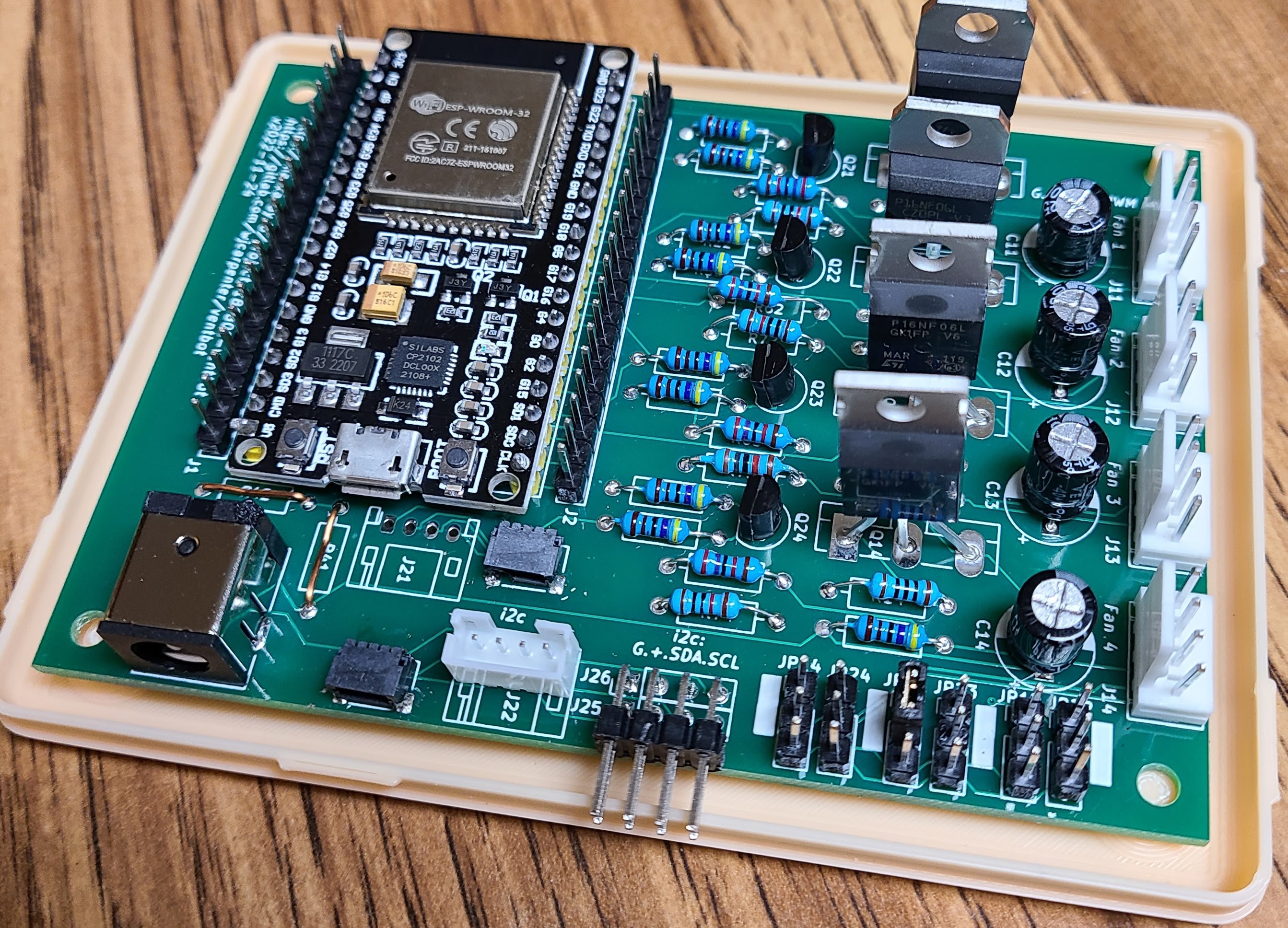
12/18/2022 at 19:01 • 0 commentsWhen I populated one of the boards and fired it up, it actually worked as designed. I'm pretty happy about that. Based on experience, I was prepared for disappointment, but I guess I got a Christmas miracle.
There are a few non-fatal changes I would make to the board if I did another run, but it looks like I won't need to do that. I'm contemplating doing another PCB iteration to clear up some of the physical layout things I described in an earlier project log.
![]()
The photo above is a fully populated (well, mostly) board. It's resting on one of the iterations of a 3D printed enclosure I'm working on.
I also need to design some brackets for putting the fans in place inside the vents, but the electronic design is pretty much done, and the firmware is pretty well settled.
-
Changes I would make if I revised the PCB
12/15/2022 at 21:06 • 0 commentsI haven't yet had a chance to populate one of my boards and test things. Naturally, I am supremely confident that it will work first time. But if I did, hypothetically, need to make more PCBs, here are a couple of things that I would change. None of these are fatal.
- In the KiCad footprint for the ESP32 module I am using, the antenna circuitry is off the end of the main board. I placed it on the PCB so it would hang over the edge. The idea is to reduce any degradation of radio signals from proximity to other components. I can't believe I didn't notice this earlier, but the actual antenna placement is between the last couple of pin headers on that end of the module. In my PCB layout, there is part of the bottom layer copper pour under the antenna. I would revise that to avoid copper directly under the antenna.
- The 12v power connector footprint is an excellent fit for the connectors that I have on hand and plan to use. I thought that it was also a good fit for some less expensive connectors (which I also have on hand) made by the same company, but it's only close and not a good match-up. I would rework that so that both of those connectors fit easily, and I might put in some additional power connector footprints so that dime-a-dozen unbranded power connectors could be used more readily. However, even without using the exact part that I selected, someone could use the kind of power connector that attaches to the PCB with wires and is then secured to the enclosure with a nut or something. I'd lay down some more obvious "+" and "-" markers on the silk screen for that possibility.
- I used right-angle horizontal footprints for the I2C JST SH and PH connectors. Those connectors come in horizontal and vertical entry formats. Since I laid out two of each footprint, I would probably change that to one horizontal and one vertical footprint for each. Too late, I discovered in my accumulating parts bucket that I had vertical connectors for both. For the JST PH connectors, it's a simple matter to use the same footprint as long as you are careful with the orientation. With the JST SH surface mount connectors, it's not really a good match-up.
- The footprint I choose for the electrolytic capacitors was a bit arbitrary, except for being radial. Hobbyists buying a few capacitors won't always have a good selection of lead spacing. I would probably lay down some additional lands for one of the leads to more easily accommodate different spacing. With a radial capacity, you can make almost anything work by bending leads. It just won't be as tidy looking as a straight-in exact fit.
- I would make the mounting holes a little bigger. They look nice and big when I'm looking at the layout in KiCad, but on the real boards they are smaller than my mental image of them. (They were manufactured exactly as I designed them. It's not a manufacturing flaw.)
- There are a couple of jumpers for some optional features. The jumpers have to be set in pairs to either "A" or "B". I laid out the 3-pin headers side by side, so it would be easy to think it was 3 pairs of 2-pin jumpers instead of 2 sets of 3-pin jumpers. I would offset them from each other a little bit so that the orientation would be obvious, and you wouldn't connect the wrong things with a jumper since it wouldn't fit.
- The placement of the connector for Fan 4 is slightly off compared to the placement of the other fans, for both the X delta and the Y absolute position. It's only a fraction of a millimeter, but it's annoying.
- Mounting hole Ref2 has some strange offset in the drill hole in the footprint report. I can't see where that comes from, but I'd try to track it down and zero it out. The other mounting holes don't have it, and the location of the overall center point is correct.
- The biggest change, which is a minor blunder, is that I somehow selected the wrong footprint for the MOSFETs. I didn't realize it until I finally went to place one on the PCB. I intended to use a TO-220 package. In some way that I can't recall, I selected TO-3P, which has a much wider lead spacing (0.215 inches). I'm able to bend the leads and fit the STP16NF06L MOSFETs, but it's inelegant.
-
The boards are back in town
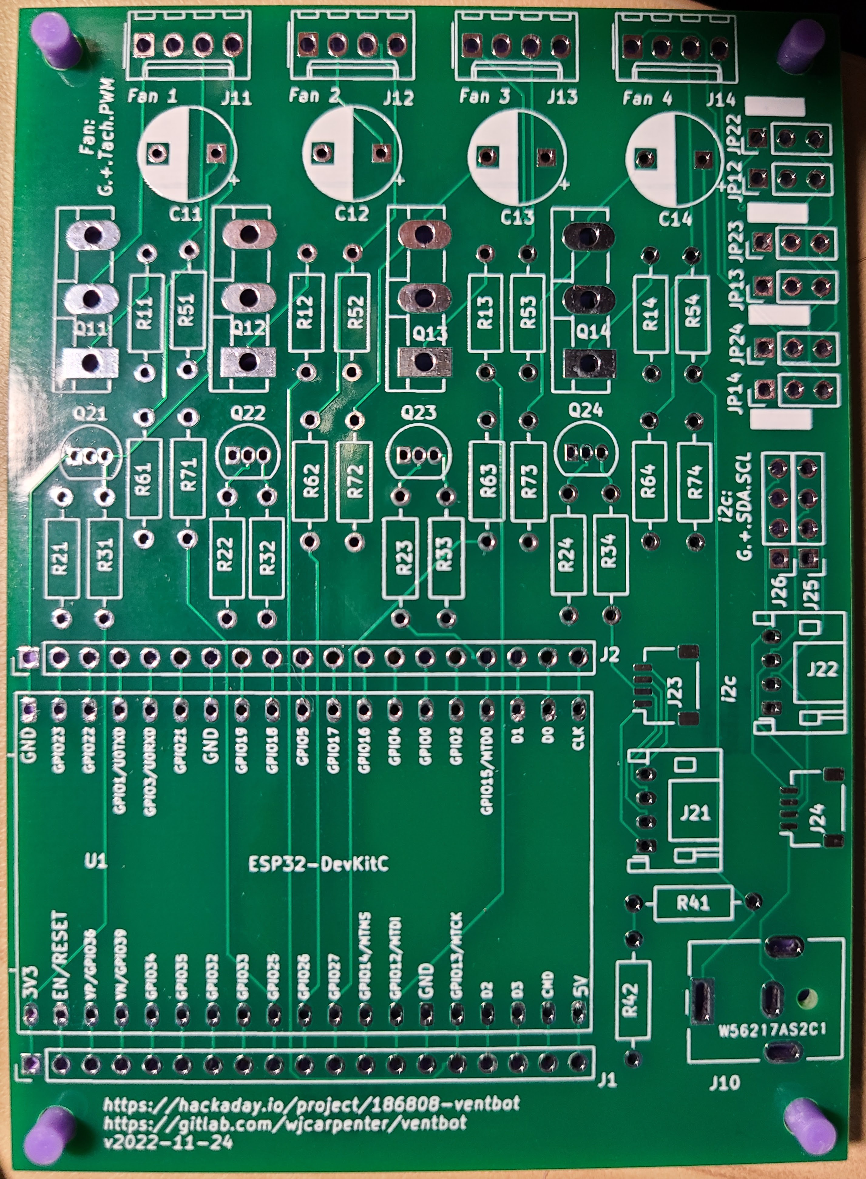
12/13/2022 at 03:11 • 0 commentsToday is an exciting day because my manufactured PC boards arrived from China. As I expected them to be, they are gorgeous. Don't be fooled by my poor photography. All the silk screen is crisp and clear, and all the plated copper lands are bright and shiny. (The purple posts are a PCB holder of mine and not part of the board.)
![]()
This round of PCBs was sponsored by PCBWay.com, by which I mean they contacted me and gave me a coupon to cover the cost of making them and shipping them to me.
![]()
It took less than 2 weeks from uploading my design files to getting the boards in my hands. That was with "global standard shipping", which is pretty reasonably priced. They also have DHL shipping, which I know from experience to be significantly faster, but it's quite a bit more expensive. (I live on the US west coast, and many China shipments come in through Los Angeles, so things get to me pretty fast once they are turned over to in-country carriers.)
It takes 1-2 days to actually manufacture the boards, and you can follow the progress as your design moves from stage to stage during the process. If you like to geek out on that stuff, it's pretty fun.
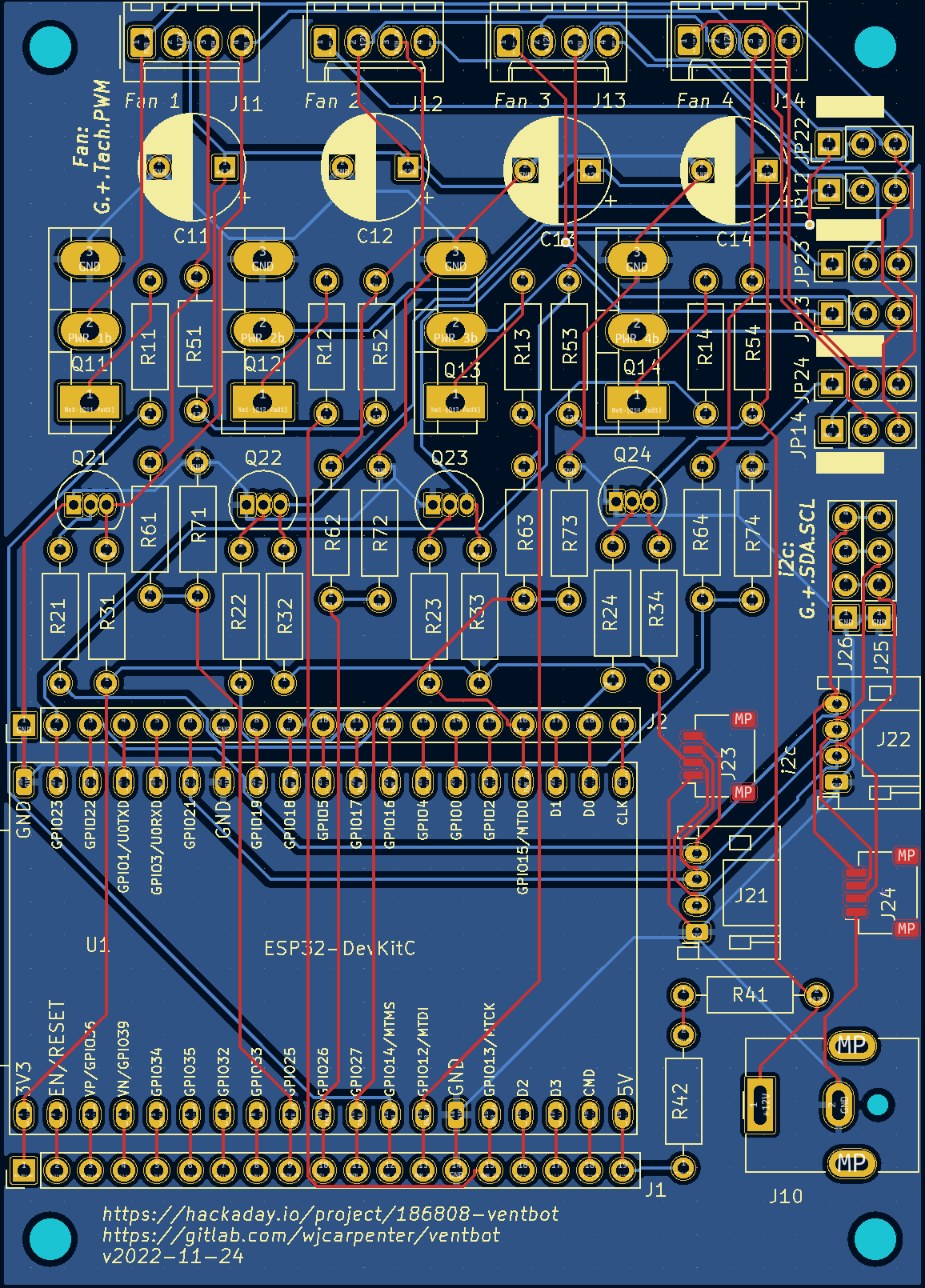
I designed the schematic and board in KiCad. I'll be uploading the KiCad design files in a bit. Here's a screenshot of KiCad's rendering of the layout:
![]()
And here is what KiCad's 3D model of the (mostly) populated board looks like.
![]()
Due to "day job" priorities, I won't be able to tinker with this too much for a few days, but here is my plan:
- Populate the board with enough components to operate Fan 1. If I find mistakes on the board, I won't have wasted too many parts.
- Prove the ESPHome firmware that I used with the breadboard still works with the PCB.
- Populate the rest of the components on the board. Even though I plan to only use 3 fans, I want to have a reference copy of the board with everything populated.
- More firmware testing with 4 fans hooked up.
Assuming all that works without discovering any design blunders, I'll finish up design of the project case and fan mounting brackets.
-
Fan auto-detection
12/03/2022 at 01:11 • 0 commentsThe board and software I've designed has connectors and logic for 4 fans. I myself only plan to use 3 fans due to physical dimensions of my vent openings. Someone else might choose to use only 1 or 2 fans. Or, out of some kind of contrarian independence streak, they might plug the fans into connectors that are not adjacent.
I want to be able to automatically detect which fans are actually present. (There is a board jumper option to have the power or PWM signal for any of fans 2, 3, or 4 to be controlled by fan 1. For the purposes of this exercise, those fans controlled that way don't count as "present".)
The autodetection turns out to be straightforward. At boot-up time, I turn on each fan in sequence at partial PWM speed. I wait a short while to let the fan spin up, and then I check its tachometer output. If it's spinning, the fan is present (and controlled by its individual signals). This only takes a few seconds, and each fan only spins for a short period of time. It only happens at boot-up, so it's not too annoying.
It is also possible to detect which fans were controlled by the signals for fan 1 in a variation of this scheme.
There's not much practical reason for doing either of these things right now, other than logging the findings. It does avoid having the ESP32 sending signals to non-existent destinations, but that's not very interesting. I guess it could be worked into a notification scheme for letting someone know if a fan went bad or came unwired or something.
-
Home Assistant integration
12/02/2022 at 21:34 • 0 commentsIn case someone else wants to build some of these, I'm designing it with no external dependencies. The devices can operate completely standalone once built and configured. However, I do run Home Assistant in my house, and it's fairly easy to integrate ESPHome devices with Home Assistant. In particular, you can define services on the ESPHome device and call those services from Home Assistant. I never fooled around with that stuff before, but I found it pleasantly easy to set up.
This might change in the final form, but here's all it takes to define the services on the ESPHome device. (Most of the logic resides in separate ESPHome scripts, not shown in this listing. Except for the names being suggestive, don't worry about the implementation logic at this point. Those will be visible in the ESPHome config file when it's ready and published.)
api:
  # These services can be called from Home Assistant for manual testing and temporary overrides.
  services:

    # Force pretending that the temperature is either in (true) or out (false) of the neutral zone.
    # Temperature sensor readings will be ignored until the duration expires or the hold is
    # canceled.
    - service: set_inout_neutral_zone_and_hold
      variables: {in_neutral_zone: bool, duration_seconds: int}
      then:
        - globals.set:
            id: IN_NEUTRAL_ZONE
            value: !lambda 'return in_neutral_zone;'
        - script.execute:
            id: S10_set_inout_neutral_zone_and_hold
            in_neutral_zone: !lambda 'return in_neutral_zone;'
            duration_seconds: !lambda 'return duration_seconds;'

    # This can be used to cancel the above hold action before the duration has expired.
    - service: cancel_hold_inout_neutral_zone
      then:
        - script.execute: S07_cancel_hold_inout_neutral_zone

    # Moves the fan speeds one step UP the ramp
    - service: crank_up
      then:
        - script.execute: S08_crank_up

    # Moves the fan speeds one step DOWN the ramp
    - service: crank_down
      then:
        - script.execute: S09_crank_down
I made a simple Home Assistant dashboard for my breadboard rig.
![]()
The bottom portion is just normal Home Assistant despiction of entities from the device. The top row of buttons were created with custom:button-card, a popular Home Assistant add-on. It doesn't have a GUI editor, but here is the raw YAML configuration for the leftmost button:
name: Step Up
show_name: true
show_icon: true
type: custom:button-card
tap_action:
  action: call-service
  service: ESPHome.ventbot_f56ed8_crank_up
entity: automation.ventbot
icon: mdi:fan-chevron-up
show_state: false
You can see that it calls the "crank_up" service defined on an ESPHome device known to Home Assistant as "ventbot_f56ed8" (the hex stuff is part of that device's specific MAC address, for disambiguation).
With these services and controls, I can:
- Turn the fans on and have them ramp all the way up to the configured full speed.
- Turn the fans off and have them ramp all the way down to off.
- At any point, I can step the fan speeds up or down to the next step of the configured ramps.
- Not shown, but when any of these services are called, they tell the device to ignore temperature triggers for a while (5 minutes).
- The cancel button turns off that hold and lets the temperature triggers have their normal effects.
-
Totally hot stuff with BMP280
12/01/2022 at 01:16 • 0 commentsAll along, I've been planning to use BMP280 sensors for temperature on this project. I have quite a few BMP280 breakout boards laying around unused. I got a few of them before I realized I could get BME280 boards that also detect relative humidity. I got a bunch more because when you try to buy BME280 boards from random overseas sellers on eBay, you stand a good chance of receiving BMP280 boards instead.
Anyhow, any temperature sensor with an I2C interface can work pretty easily with the rest of the design.
A funny thing happened. OK, two funny things. When I first added a BMP280 to the breadboard, I had some kind of brain glitch and wired it's Vcc to the 12v supply instead of the 3.3v supply. No smoke came out, but that little board was completely dead by the time I figured it out. I grabbed another BMP280 and wired it correctly on the breadboard. It worked, except it was reading a temperature of 189 C. I've never seen that behavior from a BMP280 or BME280 before. I don't even know what could make it happen. I popped it out and replaced it with a third BMP280, and things worked as expected.
So, that was weird. I'll remember to include a step for sanity testing the temperature read-outs when assembling things.
-
Some observed breadboard results
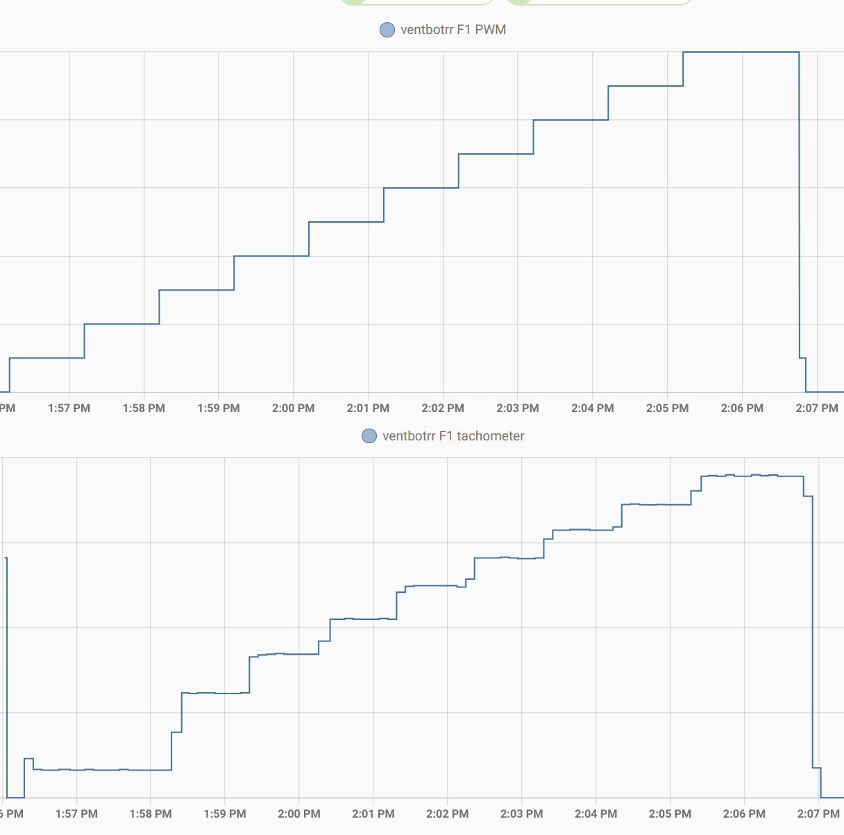
11/24/2022 at 22:14 • 0 commentsWith things wired on the breadboard as described in my last project log, I decided to see how things looked. I configured my ESPHome configuration to step up from 0% to 100% PWM in 10% increments. At each step, I waited for 60 seconds to give the fan speed time to stabilize. I logged the tach output every few seconds, with the fan pulse counts converted to RPMs. On the "PWM" line, I logged both the percentage from the point of view of the user and also the decimal fraction of the inverted signal, which is what is sent to the ESPHome LEDC control.
The results are in rough agreement with what I measured on my scope a few weeks ago.
PWM: 0.90   10
  tach:  150 rpm
  tach:  164 rpm
  tach:  162 rpm
  tach:  164 rpm
  tach:  165 rpm
  tach:  161 rpm
 -----
PWM: 0.80   20
  tach:  237 rpm
  tach:  362 rpm
  tach:  363 rpm
  tach:  359 rpm
  tach:  363 rpm
  tach:  362 rpm
 -----
PWM: 0.70   30
  tach:  459 rpm
  tach:  620 rpm
  tach:  621 rpm
  tach:  620 rpm
  tach:  624 rpm
  tach:  620 rpm
 -----
PWM: 0.60   40
  tach:  708 rpm
  tach:  851 rpm
  tach:  852 rpm
  tach:  851 rpm
  tach:  855 rpm
  tach:  854 rpm
 -----
PWM: 0.50   50
  tach:  930 rpm
  tach:  1062 rpm
  tach:  1059 rpm
  tach:  1058 rpm
  tach:  1059 rpm
  tach:  1058 rpm
 -----
PWM: 0.40   60
  tach:  1131 rpm
  tach:  1247 rpm
  tach:  1253 rpm
  tach:  1251 rpm
  tach:  1254 rpm
  tach:  1250 rpm
 -----
PWM: 0.30   70
  tach:  1313 rpm
  tach:  1419 rpm
  tach:  1418 rpm
  tach:  1416 rpm
  tach:  1418 rpm
  tach:  1418 rpm
 -----
PWM: 0.20   80
  tach:  1482 rpm
  tach:  1583 rpm
  tach:  1581 rpm
  tach:  1583 rpm
  tach:  1590 rpm
  tach:  1589 rpm
 -----
PWM: 0.10   90
  tach:  1646 rpm
  tach:  1737 rpm
  tach:  1736 rpm
  tach:  1744 rpm
  tach:  1740 rpm
  tach:  1744 rpm
 -----
PWM: 0.00   100
  tach:  1804 rpm
  tach:  1913 rpm
  tach:  1911 rpm
  tach:  1913 rpm
  tach:  1917 rpm
  tach:  1913 rpm
Here is a nice graphical result from a later similar test.
![]()
-
Modified PWM and tach wiring
11/24/2022 at 21:58 • 0 commentsI had a dream of a fairly simple control arrangement for the fans. Since most fans don't switch off at 0% PWM duty cycle, I designed in an N-channel MOSFET to cut the ground link to the fan when I wanted to turn it completely off. That was a grand idea until I wired it up on the breadboard and found that the fan kept gently turning even with the MOSFET switched off. Hmmm. Maybe the reason is obvious to someone who does electronics for a living, but I never completely connected the dots. I did figure out experimentally that the fan shut off completely if I disconnected both the PWM input and the tach output. My theory is that fan motor was getting enough leakage to ground through those lines to give it a feeble spin.
I first attacked the PWM input line. Instead of connecting it directly to the fan PWM line, I connected it to a 2N3904 NPN transistor. The PWM signal went to the base, the collector went to 3.3v, and the emitter went to ground. I also tried it with emitter and collector swapped. Both ways worked in the sense of controlling the PWM to the fan, but it didn't affect the fan slowly turning at 0% PWM. (This arrangement acts as a sort of inverter of the PWM signal, so I had to subtract the desired value from 100% to apply to the control line. I could also have just marked the pin inverted in the ESPHome config, but that made some other parts less clear.) I eventually found that ESPHome would let me explicitly turn off the PWM signal output, and that would stop the final piece of fan movement (again, as long as the tach line was not connected).
(I also tried connecting the same power control from the MOSFET to the base of the NPN to try to disable the PWM signal going through the emitter/collector pins. That didn't work, but I didn't pursue it.)
One down, one to go.
The tach signal is trickier. The same approach doesn't work for that. I'm using the ESPHome pulse_counter component, and there's no way to explicitly switch it off, probably because it's an input signal. I tried the same tricks as for the PWM signal, but they didn't work.
While experimenting, I "cooked" 2 ESP32 boards. When that happened, I thought maybe the boards weren't really happy with my 12v inputs to the 5v ESP32 power pin. I changed things to run the fans off 12v and the ESP32 from the USB connector. My plan was to figure out some kind of power conditioning later, but I have more or less concluded that I killed the boards by feeding them some variation of a 12v tach signal on the ESP32 3.3v GPIOs. Why did it kill things now instead of over the last couple of weeks of messing around with that 12v signal? I hypothesize that there wasn't enough current at 12v to do damage, and something in one of my experiments let more current through on the same line. (That might have happened by me mis-wiring something as I moved jumpers around. No smoke came out, but some parts of the ESP32 boards got pretty hot.)
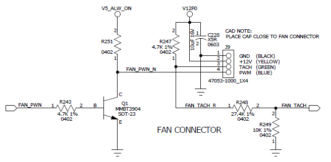
After burning up the second ESP32 board, I decided on the irrational course of trying to figure out what I should do instead of poking electricity into places where it didn't want to be. Looking through all my notes about fan interfaces, I re-read this StackExchange reply from Michael Karas. It's a clear explanation, and includes helpful info in the comments below the posting. I don't know the original source of the circuit diagram he posted. It's the same as the circuit given in this blog by a different author, who describes it as a "detailed portion of a bit old official motherboard schematic" and gives the missing value for R251 as 4.7k. It's not from the 2005 version of the Intel spec for PWM fans.
![]()
When I read it a while back, I thought, "Nice, but I don't need anything this complicated." It turns out I do need something that complicated. The PWM part of the circuit is pretty much what I ended up with. I wired up the tach part on the breadboard according to this schematic, and it worked as desired.
The fan stops when I want it to stop if:
- I wire things up as in that schematic.
- I use the power control line on the MOSFET to sever the ground link.
- I use ESPHome's explicit turn_off call on the PWM signal when it goes to 0%.
- I take into consideration the signal inversion on the PWM signal.
Ventbot: warm side cool, cool side warm
A DIY register booster project to even out the temps around my home.