Ted Yapo
-
Fractals re-written in assembly: 560 bytes
01/17/2017 at 19:41 • 0 commentsI re-wrote the fractal-generation code in assembly to see what gains I could make. Just a simple manual translation of the code came out to 560 bytes (320 instructions), as opposed to the 1019 bytes of compiled C. It produces the same output as the C version. There are places it could be optimized, but I just wanted a baseline written this way. As I often find in PIC assembly, there's a lot of loading and storing to do (you gotta love RISC), and that overhead before each subroutine call is expensive. The PIC16F1718 has a linearly-addressable memory and two auto-incrementing (or decrementing) pointer registers (FSR0/FSR1), and these can be used to automate the parameter passing overhead. I have some prototype code written with a new framework that should streamline numerical code like this, but haven't had a chance to re-implement the fractal code in it yet. I am anxious to see how much it improves things here.
All this is leading up to trying to get the ray tracer in 1kB (I can't let go). I also worked out a way to avoid square roots in testing intersections with spheres, which I'll detail in another log. That alone could save a decent chunk of code.
The naive assembly fractal code is listed here. I know of at least a few places it could be tuned up - not the least of which is inlining the four main calls - that's 8 instructions (14 bytes!) right there. But not terribly interesting ones.
;;; ;;; generate VGA Mandelbrot set in assembly ;;; #include <p16f1718.inc> ;;RADIX DEC ERRORLEVEL -302 ERRORLEVEL -305 __CONFIG _CONFIG1, _FOSC_INTOSC & _WDTE_OFF & _PWRTE_ON & _MCLRE_ON & _CP_OFF & _BOREN_ON & _CLKOUTEN_OFF & _FCMEN_ON __CONFIG _CONFIG2, _WRT_ALL & _PPS1WAY_OFF & _ZCDDIS_ON & _PLLEN_ON & _STVREN_OFF & _BORV_LO & _LPBOR_OFF & _LVP_ON ;;; ;;; h/w interface definition ;;; #define REG_OE_bar b'00010000' #define TIMER_en b'00001000' #define WE_bar b'00000001' #define WE_bit 0 #define OE_bar b'00000010' #define CP_en b'00001000' #define MR_en b'00100000' #define CP_bar b'00000100' #define CP_bit 2 #define MR_bar b'00010000' #define VSYNC b'10000000' #define HSYNC b'01000000' #define RGB(r, g, b) (((r & 0x3) << 4) | ((g & 0x3) << 2) | (b & 0x3)) #define H_FRONT_PORCH .16 #define H_SYNC_PULSE .96 #define H_BACK_PORCH .48 #define V_FRONT_PORCH .10 #define V_SYNC_PULSE .2 #define V_BACK_PORCH .33 #define MAXITER .255 #define ESCAPE_RADIUS 0xc0 #define COMPONENT_RADIUS 0xf8 ;#define WHOLE_SET #ifdef WHOLE_SET #define IMAG_MIN 0xec00 #define REAL_MIN 0xd800 #define IMAG_STEP 0x0015 #define REAL_STEP 0x0015 #else #define IMAG_MIN 0xff00 #define REAL_MIN 0xe800 #define IMAG_STEP 0x0001 #define REAL_STEP 0x0001 #endif ;;; ;;; variables ;;; cblock 0x20 ;; WRITE_SRAM_BYTES sram_value sram_count ;; WRITE_LINE line_vsync_value line_rgb_value line_count line_loop_count ;; WRITE_FRAME row_l row_h col_l col_h ;; mandelbrot calculation iter a_l a_h b_l b_h c_l c_h d_l d_h dc_l dc_h dd_l dd_h aa_l aa_h bb_l bb_h aa_plus_bb_l aa_plus_bb_h red green blue ;; MUL16 mul_a_l mul_a_h mul_a_2 mul_a_3 mul_b_l mul_b_h mul16_flags prod_0 prod_1 prod_2 prod_3 ;; ABS16 abs_l abs_h ;; MUL16_SIGNED mul_sign ;; MUL16_SHIFT mul_shift_count endc ;;; ;;; reset vector ;;; ORG 0 call SETUP_PERIPHERALS call LOAD_MODE call WRITE_FRAME call RUN_MODE MAIN_LOOP: bra MAIN_LOOP SETUP_PERIPHERALS: ;; intosc 32 MHz BANKSEL OSCCON movlw b'11110000' movwf OSCCON ;; select digital I/O BANKSEL ANSELA clrf ANSELA clrf ANSELB clrf ANSELC ;; set TRIS bits: all outputs BANKSEL LATA clrf LATA clrf LATB clrf LATC BANKSEL TRISA clrf TRISA clrf TRISB clrf TRISC return LOAD_MODE: BANKSEL LATA movlw REG_OE_bar | TIMER_en movwf LATA ;; toggle CP with MR low to reset address counter movlw WE_bar | OE_bar | CP_en | CP_bar | MR_en | MR_bar movwf LATB movlw WE_bar | OE_bar | CP_en | CP_bar&0 | MR_en | MR_bar movwf LATB movlw WE_bar | OE_bar | CP_en | CP_bar | MR_en | MR_bar movwf LATB ;; bring out of reset movlw WE_bar | OE_bar | CP_en | CP_bar | MR_en | MR_bar&0 ; movwf LATB ;; data lines all outputs BANKSEL TRISC clrf TRISC BANKSEL LATA return RUN_MODE: ;; data lines all inputs BANKSEL TRISC movlw 0xff movwf TRISC BANKSEL LATB ;; reset address counter, then let it rip movlw WE_bar | OE_bar&0 | CP_en&0 | CP_bar&0 | MR_en | MR_bar movwf LATB movlw WE_bar | OE_bar&0 | CP_en&0 | CP_bar&0 | MR_en&0 | MR_bar&0 ; movwf LATB movlw REG_OE_bar&0 | TIMER_en&0; movwf LATA return ;;; ;;; write a series of identical bytes to SRAM ;;; WRITE_SRAM_BYTES: movf sram_value, W movwf LATC SRAM_LOOP: ;; toggle WE to write value bcf LATB, WE_bit bsf LATB, WE_bit ;; toggle CP to increment address bcf LATB, CP_bit bsf LATB, CP_bit decfsz sram_count bra SRAM_LOOP return ;;; ;;; write the horizontal sync and porches ;;; WRITE_HSYNC: ;; write the H. front porch movf line_vsync_value, W iorlw HSYNC movwf sram_value movlw H_FRONT_PORCH movwf sram_count call WRITE_SRAM_BYTES ;; write the H. sync pulse movf line_vsync_value, W movwf sram_value movlw H_SYNC_PULSE movwf sram_count call WRITE_SRAM_BYTES ;; write the H. back porch movf line_vsync_value, W iorlw HSYNC movwf sram_value movlw H_BACK_PORCH movwf sram_count call WRITE_SRAM_BYTES return ;;; ;;; write a series of VGA scanlines to SRAM ;;; WRITE_SCANLINE: call WRITE_HSYNC ;; loop 4x writing 160 pixels each time (total 640) movf line_vsync_value, W iorlw HSYNC movwf sram_value movf line_rgb_value, W iorwf sram_value movlw .4 movwf line_loop_count SCANLINE_LOOP: movlw .160 movwf sram_count call WRITE_SRAM_BYTES decfsz line_loop_count bra SCANLINE_LOOP decfsz line_count bra WRITE_SCANLINE return ;;; ;;; 16x16->32 unsigned multiply ;;; MUL16: clrf prod_0 clrf prod_1 clrf prod_2 clrf prod_3 clrf mul_a_3 clrf mul_a_2 MUL16_LOOP: btfss mul_b_l, 0 bra MUL16_NO_ADD movf mul_a_l, W addwf prod_0 movf mul_a_h, W addwfc prod_1 movf mul_a_2, W addwfc prod_2 movf mul_a_3, W addwfc prod_3 MUL16_NO_ADD: lslf mul_a_l rlf mul_a_h rlf mul_a_2 rlf mul_a_3 lsrf mul_b_h movf STATUS, W movwf mul16_flags rrf mul_b_l movf mul_b_l, W movf STATUS, W andwf mul16_flags btfss mul16_flags, Z bra MUL16_LOOP return ;;; ;;; 16x16->32 signed multiply ;;; MUL16_SIGNED: movf mul_a_h, W movwf mul_sign btfss mul_a_h, 7 bra MUL16_FLIP_A_DONE comf mul_a_h comf mul_a_l incfsz mul_a_l bra MUL16_FLIP_A_DONE incf mul_a_h MUL16_FLIP_A_DONE: movf mul_b_h, W xorwf mul_sign btfss mul_b_h, 7 bra MUL16_FLIP_B_DONE comf mul_b_h comf mul_b_l incfsz mul_b_l bra MUL16_FLIP_B_DONE incf mul_b_h MUL16_FLIP_B_DONE: call MUL16 btfss mul_sign, 7 return comf prod_0 comf prod_1 comf prod_2 comf prod_3 incfsz prod_0 return incfsz prod_1 return incfsz prod_2 return incf prod_3 return ;;; shift right 8+W bits MUL16_SHIFT: movwf mul_shift_count movf prod_1, W movwf prod_0 movf prod_2, W movwf prod_1 movf prod_3, W movwf prod_2 MUL16_SHIFT_LOOP: asrf prod_2 rrf prod_1 rrf prod_0 decfsz mul_shift_count bra MUL16_SHIFT_LOOP return ;;; ;;; calculate escape iteration for complex point c + di ;;; under: Z <- Z^2 + c + di ;;; Z = a + bi MANDELBROT_ITERATION: clrf a_l clrf a_h clrf b_l clrf b_h movlw MAXITER movwf iter MANDELBROT_LOOP: ;; aa = a * a movf a_l, W movwf mul_a_l movwf mul_b_l movf a_h, W movwf mul_a_h movwf mul_b_h call MUL16_SIGNED ;; test aa for escape movf prod_3, W andlw COMPONENT_RADIUS btfss STATUS, Z return ;; shift aa 12 bits post-mul movlw 4 call MUL16_SHIFT movf prod_0, W movwf aa_l movf prod_1, W movwf aa_h ;; bb = b * b movf b_l, W movwf mul_a_l movwf mul_b_l movf b_h, W movwf mul_a_h movwf mul_b_h call MUL16_SIGNED ;; test bb for escape movf prod_3, W andlw COMPONENT_RADIUS btfss STATUS, Z return ;; shift bb 12 bits post-mul movlw 4 call MUL16_SHIFT movf prod_0, W movwf bb_l movf prod_1, W movwf bb_h ;; b = 2 * a * b + d movf a_l, W movwf mul_a_l movf a_h, W movwf mul_a_h movf b_l, W movwf mul_b_l movf b_h, W movwf mul_b_h call MUL16_SIGNED ;; shift only 11 bits to effectively multiply by 2 movlw 3 call MUL16_SHIFT movf d_l, W addwf prod_0, W movwf b_l movf d_h, W addwfc prod_1, W movwf b_h ;; a = aa - bb + c movf aa_l, W movwf a_l movf bb_l, W subwf a_l movf aa_h, W movwf a_h movf bb_h, W subwfb a_h movf c_l, W addwf a_l movf c_h, W addwfc a_h ;; test aa + bb for escape movf bb_l, W addwf aa_l movf bb_h, W addwfc aa_h, W andlw ESCAPE_RADIUS btfss STATUS, Z return decfsz iter bra MANDELBROT_LOOP return ;;; ;;; write the VGA frame to SRAM ;;; WRITE_FRAME: ;; write V. back porch clrf line_rgb_value movlw VSYNC movwf line_vsync_value movlw V_BACK_PORCH movwf line_count call WRITE_SCANLINE #define COUNTER16H(x) (HIGH(x)+1) #define COUNTER16L(x) LOW(x) ;; init d movlw LOW(IMAG_MIN) movwf d_l movlw HIGH(IMAG_MIN) movwf d_h movlw COUNTER16H(.480) movwf row_h movlw COUNTER16L(.480) movwf row_l ROW_LOOP: movlw VSYNC movwf line_vsync_value call WRITE_HSYNC ;; init c movlw LOW(REAL_MIN) movwf c_l movlw HIGH(REAL_MIN) movwf c_h movlw COUNTER16H(.640) movwf col_h movlw COUNTER16L(.640) movwf col_l COL_LOOP: call MANDELBROT_ITERATION movlw VSYNC | HSYNC movwf sram_value movlw 0x3f andwf iter movf iter, W andlw 0x0c swapf iter iorwf iter, W andlw 0x3f iorwf sram_value movlw .1 movwf sram_count call WRITE_SRAM_BYTES ;; increment c movlw LOW(REAL_STEP) addwf c_l movlw HIGH(REAL_STEP) addwfc c_h ;; end of col loop decfsz col_l bra COL_LOOP decfsz col_h bra COL_LOOP ;; increment d movlw LOW(IMAG_STEP) addwf d_l movlw HIGH(IMAG_STEP) addwfc d_h ;; end of row loop decfsz row_l bra ROW_LOOP decfsz row_h bra ROW_LOOP ;; write V. front porch clrf line_rgb_value movlw VSYNC movwf line_vsync_value movlw V_FRONT_PORCH movwf line_count call WRITE_SCANLINE ;; write V. sync pulse clrf line_vsync_value movlw V_SYNC_PULSE movwf line_count call WRITE_SCANLINE ;; write two bytes of back porch to reset address counter movlw VSYNC | HSYNC movwf sram_value movlw .2 movwf sram_count call WRITE_SRAM_BYTES return END -
640x480 RLE Wrencher (4409 Bytes)
01/06/2017 at 23:50 • 19 commentsI had to do it.
![]()
The logo plus decoding code takes up 2519 14-bit instructions (4409 bytes). I used a simple RLE compression and stored the compressed data in a header file. I only compressed the left half image, then decompressed the runs in reverse for the right half. The whole code is uploaded here, but the decompression part looks like:
void GenerateFrame()
{
  GenerateLine( VSYNC   , RGB(0, 0, 0),  33);  // V back porch

  const uint8_t *data_ptr = rle_wrencher;
  uint16_t row = 480;
  do {
    write_SRAM_bytes( VSYNC | HSYNC   | 0 , 16);  // H front porch
    write_SRAM_bytes( VSYNC | HSYNC&0 | 0 , 96);  // H sync pulse
    write_SRAM_bytes( VSYNC | HSYNC   | 0 , 48);  // H back porch

    const uint8_t *row_ptr = data_ptr;

    // left half image
    uint8_t color = 0;
    uint8_t num_runs = *data_ptr++;
    if (num_runs){
      do {
        uint8_t run_length = *data_ptr++;
        write_SRAM_bytes( VSYNC | HSYNC   | color, run_length);
        color ^= 0x3f;
      } while (--num_runs);
    } else {
      write_SRAM_bytes( VSYNC | HSYNC   | 0, 160);
      write_SRAM_bytes( VSYNC | HSYNC   | 0, 160);
    }

    // right half image (runs processed in reverse)
    color ^= 0x3f;
    num_runs = *row_ptr;
    if (num_runs){
      do {
        uint8_t run_length = *--data_ptr;
        write_SRAM_bytes( VSYNC | HSYNC   | color, run_length);
        color ^= 0x3f;
      } while (--num_runs);
    } else {
      write_SRAM_bytes( VSYNC | HSYNC   | 0, 160);
      write_SRAM_bytes( VSYNC | HSYNC   | 0, 160);
    }
    data_ptr += *row_ptr;

  } while (--row);

  GenerateLine( VSYNC   , RGB(0, 0, 0),  10);  // V front porch
  GenerateLine( VSYNC&0 , RGB(0, 0, 0),  2);   // V sync pulse
  write_SRAM_bytes( VSYNC | HSYNC | 0, 2);     // end of vsync; resets counter
}
I really wanted to fit this into 1kB, but ran out of time.Quadtrees?
I also experimented with quadtree compression, which should take better advantage of the solid 2D areas (not just 1D runs). The best strategy I found was to compress the top and bottom halves as 256x256 blocks (bottom visualized here):
![]()
Again, symmetry would be used to create the right side. I got the data down to 1047 bytes this way, but didn't think I could add the decompression code *and* find a way to make it all fit in 1kB, so I abandoned the effort.
I think you probably could get this image into 1kB, though, if you really worked at it.
Now, back to other projects...
For those that want to try compressing this 640x480 rendering of the wrencher, here is the one I used as a png. I do not know anything about the intellectual property status of this image, so, you know...don't sue me or anything. I make no representations whatsoever about rights to use this logo or this specific rendering of it. I hear it's a touchy subject - but then again, there are a number of instances of people using the logo, then not being sued for trademark infringement, so that sounds like failure-to-enforce. But failing to enforce copyright doesn't weaken the copyright, so ... whatever. Then again, this is their site, so if they have an issue with this, they should send themselves a takedown notice.
![]()
-
Other Video Formats (SVGA/Composite)?
01/06/2017 at 14:08 • 10 commentsSo, 640x480 VGA is nice, but what else could you do with this hardware (or something very similar?). The vertical-sync address reset is very flexible regarding frame size - my initial tests of the board used only an 8-pixel frame so I could see it all on the scope. By changing the dot clock, you could have the board play out video in whatever format you wanted, limited basically by two factors: SRAM size and maximum clock frequency.
SRAM Size
I took a look at this page to determine the SRAM requirements for various SVGA modes. With this adapter, each dot clock in the whole frame needs a slot in the SRAM. For example, in 640x480, a total of 800x525 = 420000 bytes are required, since the video frame consists of 525 lines of 800 dot clocks each. Here's a summary of some common modes and what size memories they fit into:
MODE Line Width Lines Bytes Req'd 512k x 8 1M x 8 2M x 8 4M x 8 640x480 800 525 420000 X X X X 768x576 976 597 582672 X X X 800x600 1024 625 640000 X X X 1024x768 1344 806 1083264 X X 1280x1024 1688 1066 1799408 X X I didn't bother with modes above this, because the required clock speed becomes the limiting factor.
As you can see, 640x480 is the only common resolution that fits in the 512k SRAM I used - to go any higher, you'd need a bigger one. The (5x) 74AC163 counters could generate 1M addresses (20 bits); beyond that, and you'd need to expand the counter.
Clock Frequency
I looked at the minimum VESA-standard refresh rates for the above modes (typically 60 Hz), what dot clock frequencies are required, and the period of this frequency:
MODE Refresh Dot Clock Period 640x480 60 Hz 25.175 MHz 39.7 ns 768x576 60 Hz 34.96 MHz 28.6 ns 800x600 56 Hz 36 MHz 27.8 ns 1024x768 60 Hz 44.9 MHz 22.3 ns 1280x1024 60 Hz 108 MHz 9.26 ns According to Ti's datasheet, the 74AC163 will count at 103 MHz over commercial temperatures at 5V. But, the maximum propagation delay from the clock to the outputs is 15 ns. I used a 12ns SRAM, although I see them (in less hacker-friendly packages) down to 6ns. With the SRAM I used, you might be limited to a (12+15 =) 27 ns cycle time, which could do 800x600 but no higher. Moving to a 6ns SRAM allows a cycle time of (6+15 = 21), which with some tricks and tweaks might get you to 1024x768.
FPGAs?
I couldn't implement the counting and reset logic in an FPGA for this project because I thought the FPGA code might count against the 1kB limit - maybe it didn't; who knows. But, it certainly seems like a small FPGA might do the counting and reset logic easily, and do it faster and more compactly than the discrete logic packages. Combined with a larger, faster SRAM, this might make a nice system. With the extra logic afforded by the FPGA, you might even add a way to write to the SRAM while the VGA output is active - the biggest missing piece in this simple system. Of course, you could also implement a more traditional split-counter and synch-generation system while you were at it.
Composite Video?
Last, and possibly least, would be generation of composite video (NTSC or PAL). There's enough memory on the board I built to store a nice NTSC frame. The clock frequency of 25.175 MHz is more than 7x the color-burst frequency at 3.58 MHz, so you might even be able to generate a full-color signal by directly synthesizing the 3.58 MHz color subcarrier along with the luminance signal. I think the only hardware modification required would be to ditch the three 2-bit DACs and replace them with a single 6-bit DAC. For 6 bits, you can use 1% resistors in an R/2R ladder.
Arbitrary Waveforms?
At its heart, this system is an arbitrary waveform generator, so why not use it as such? I'm guessing you could go to 35 MHz clock frequency with this board, maybe a little more. That would give you a theoretical maximum sinewave output frequency of 17.5 MHz (yes, you'd have to filter it heavily). A more realistic limit might be 10 points per cycle, or 3.5 MHz maximum output. It's not great compared to commercial offerings, but might find some use around the lab.
Next Up
I have one more image I want to get displayed on the monitor with some minimal code, then I'm going to consider this project done. It was a fun distraction, but I have other projects to get back to :-)
-
Zero Instruction Elapsed Timer
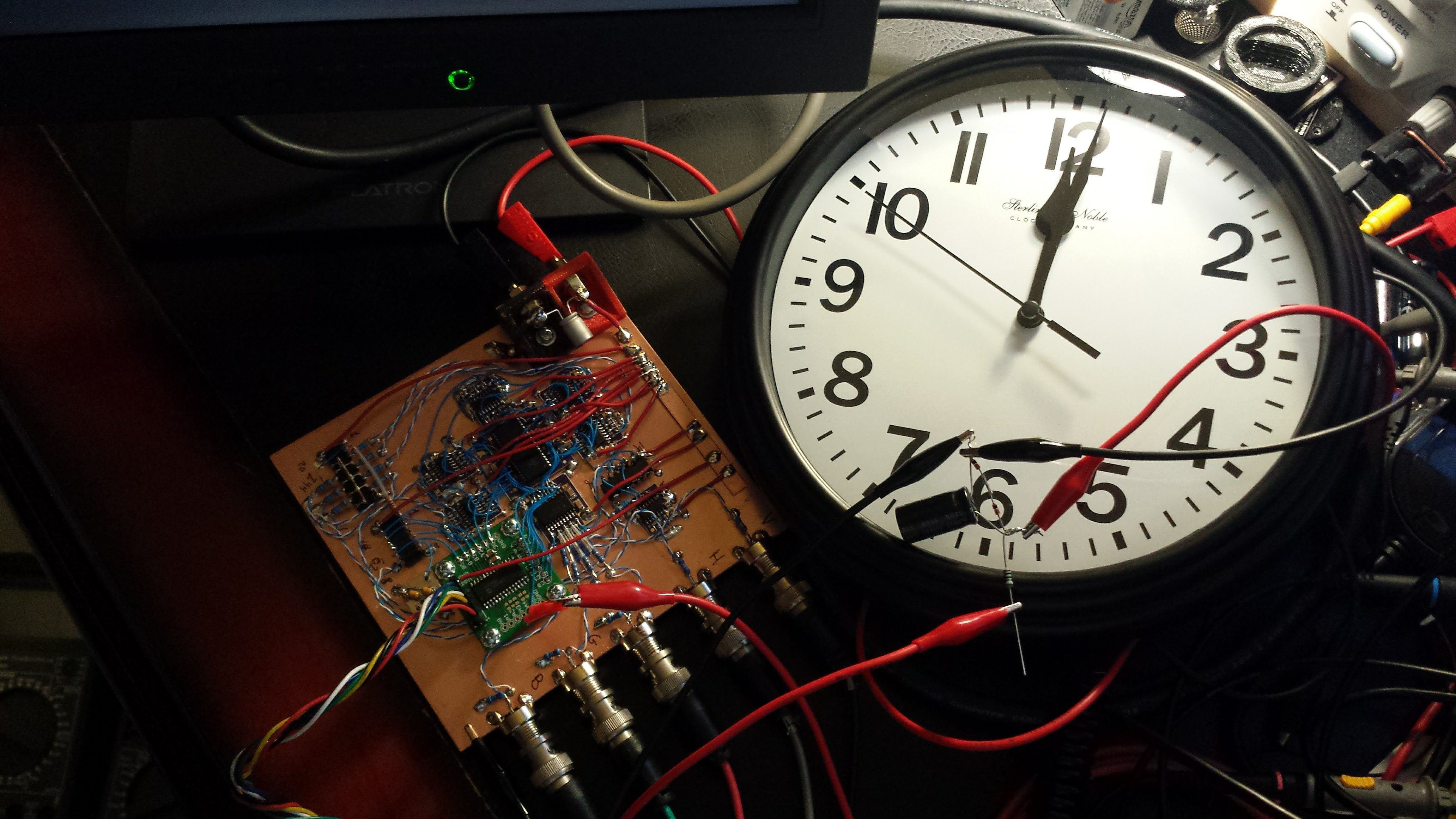
01/06/2017 at 02:04 • 8 commentsSince these images take so long (hours) to generate, I wanted to be able to time them and report exact run-times. But, I didn't want to add any extra instructions to do it, so I decided to use a very simple, low-tech approach.
![]()
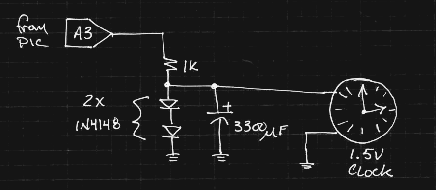
I found this clock for $3.88 at Walmart. It normally runs off an AA battery. Instead, I'm running it from an unused output line on the PIC:
![]()
The resistor and diodes form a crude 1.4 V regulator. The clock wouldn't run with small capacitors - the hand would twitch but not fully advance. The mechanism must need a hefty current pulse to actually advance it.
I was able to set and clear a bit in the code just by changing the constants that get written to the ports, so I didn't increase the code size at all.
To use the timer, you set the clock to 12:00 before a run, then come back and read off the elapsed time after it's done. For very long runs, you just have to check the clock every 12 hours. This would at first appear to violate the Nyquist criterion, since the period of the clock is 12 hours, meaning you have to sample at least every 6 hours, but it doesn't :-)
I probably won't have timing data before the contest deadline, but I'll post it here when I have it.
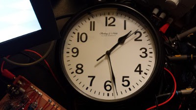
The ray-tracing took 1 hour and 28 minutes to run:
![]()
I'm timing the fractal code now. I think that takes longer...
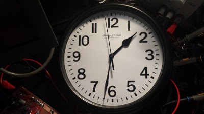
Technically, I was correct, the fractal code took longer, but not much: 1 hour and 32 minutes. Funny, they're pretty well matched.
![]()
I didn't wait around while I was running these things before - I always kicked them off before going to bed, or something like that.
-
Finally: Ray-tracing on an 8-bit PIC (not 1kB)
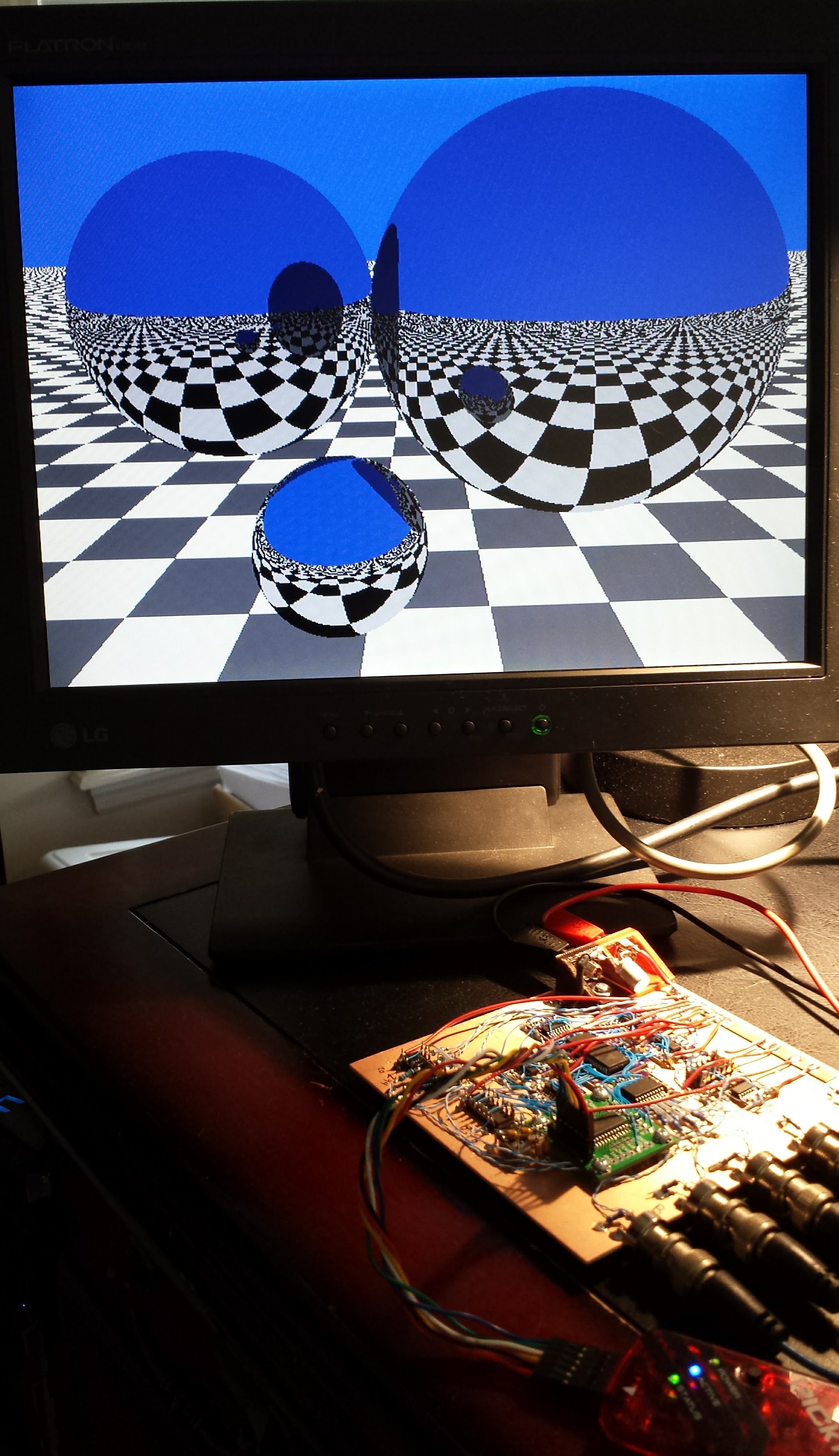
01/05/2017 at 17:33 • 0 commentsOK, I'll clog your feed with one more portrait-aspect image (sorry for all of them). I finally got the ray-tracer doing the right thing. It's still 8.3kB of code, which is the best I'm going to be able to do before the contest deadline, but it works. The fractals in 1kB will have to be the code for the contest, but here's ray-tracing on an 8-bit PIC:
![]()
The wavy lines are moiré patterns caused by the monitor pixels beating with the camera pixels; they're not in the generated image. I uploaded updated source code with the latest epsilon fix. The code ain't pretty, but "it works."
-
24-bit Float Fail
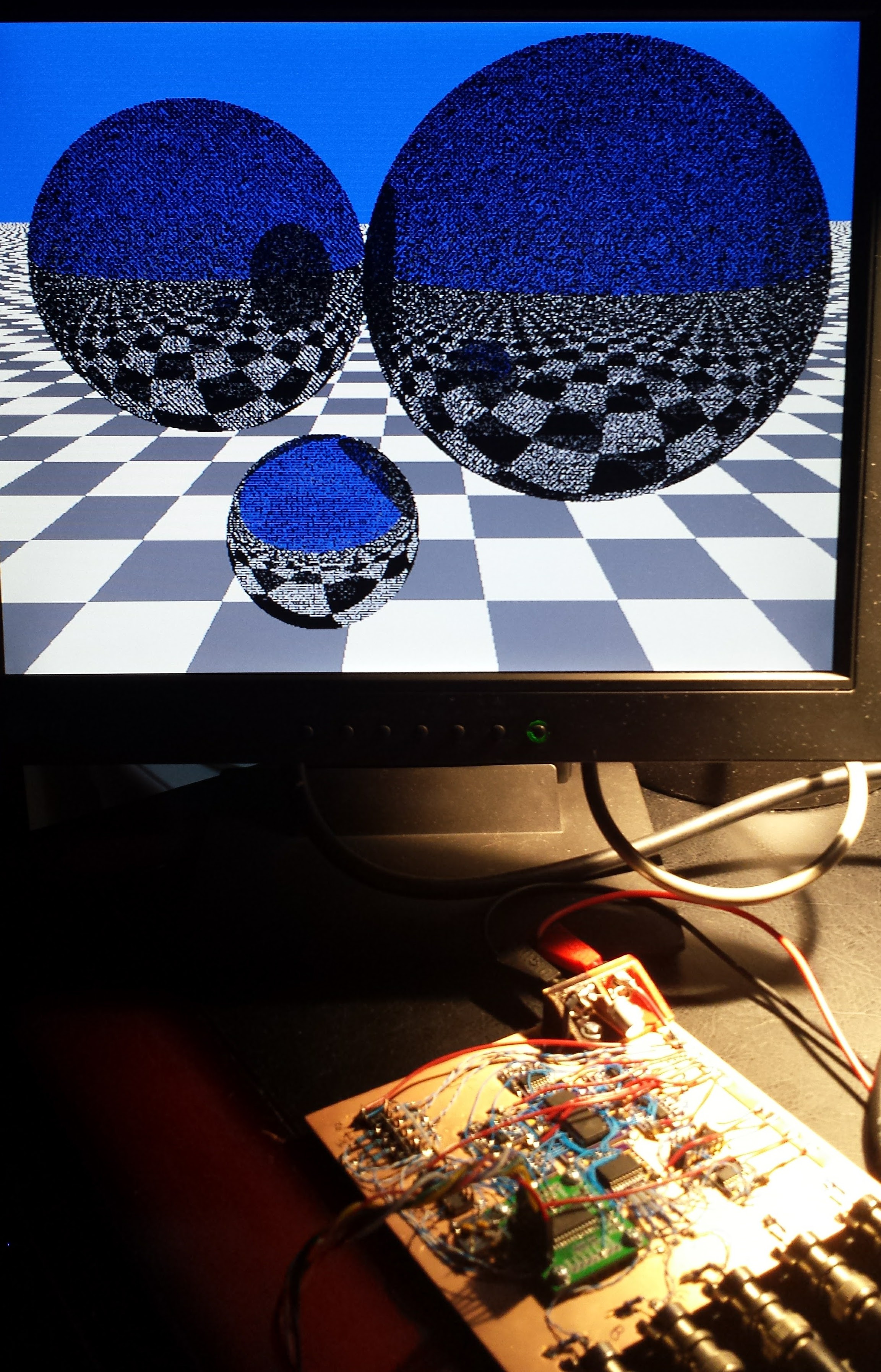
01/05/2017 at 13:00 • 18 commentsIt turns out that the 24-bit floating point implemented in the XC8 compiler requires a few tweaks of the ray-tracing code. My goal is to re-write this all in 16 (or 24) bit fixed point, anyway, but the code I had ready used floats. Here's the problem:
![]()
The noise on the spheres is caused when rays bounce off, then are found intersect the sphere again immediately. This happens because if the origin of the reflected ray is right on the surface of the sphere, it's ambiguous which side the ray originates on - the dropout points above are where the origin of the reflected ray were found to be inside the sphere, so the ray got trapped in there instead of bouncing off normally. The classic solution to this classic problem is to add a small offset (epsilon) to the reflected ray origin to ensure the reflected ray remains outside - and the required magnitude of this offset depends on the numerical precision used.
I tested this code on my linux box with IEEE 32-bit floating point, where my chosen epsilon was sufficient. Porting the code to the PIC with 24-bit floats looks like it requires a few tweaks. I changed one line to bump epsilon:
      // reflect from sphere
      float eps = 0.1;
and I have it running again.
CONTEST DISCLAIMER: this code is 8.3kB in size.
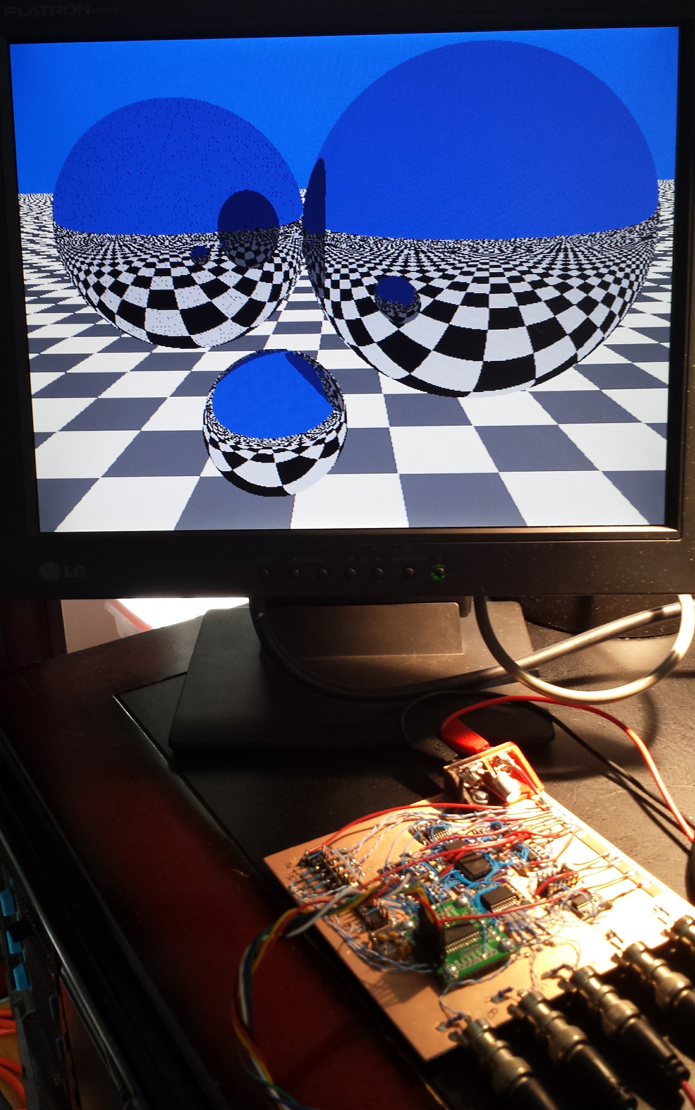
Second Try - Slightly Less Fail
My epsilon is still too large - dropouts on the left-hand sphere only now. It's running again...
![]()
-
Can I have 9kB if I enter nine times?
01/05/2017 at 01:35 • 4 commentsI got the ray-tracer to fit - into the PIC, anyway. At 8473 bytes, it's way over the 1kB limit, unfortunately. The good news is that this is without any serious attempts at size optimization - it's using the free XC8 compiler's native 24-bit floating point in pure C, and it was written more for simplicity than compactness. I figured once I got it working, I could start cutting corners to make a version fit.
The bad news is that since this thing is going to take so long to run, I need to start running the code I have if I want a chance at it finishing before the contest deadline - my rough estimates put it at 8 hours, but it could be twice as long or more. So, I kicked it off a few minutes ago.
So, it won't be in 1kB, but I might get a ray-tracer on an 8-bit PIC in true VGA resolution. In some universe, that's worth doing anyway :-)
I'll post an image when it appears. I uploaded the code already - you can see that it could use some serious optimization.
The one issue I had was that the XC8 compiler doesn't support recursive functions, which make ray tracing so much easier. I had to convert to an iterative approach. I've written four (or maybe five) ray tracers of varying complexity for different applications (graphics / optics / solar concentrator design) since the late 1980s, but I think this was the first time I couldn't use recursion. It was a neat little twist.
-
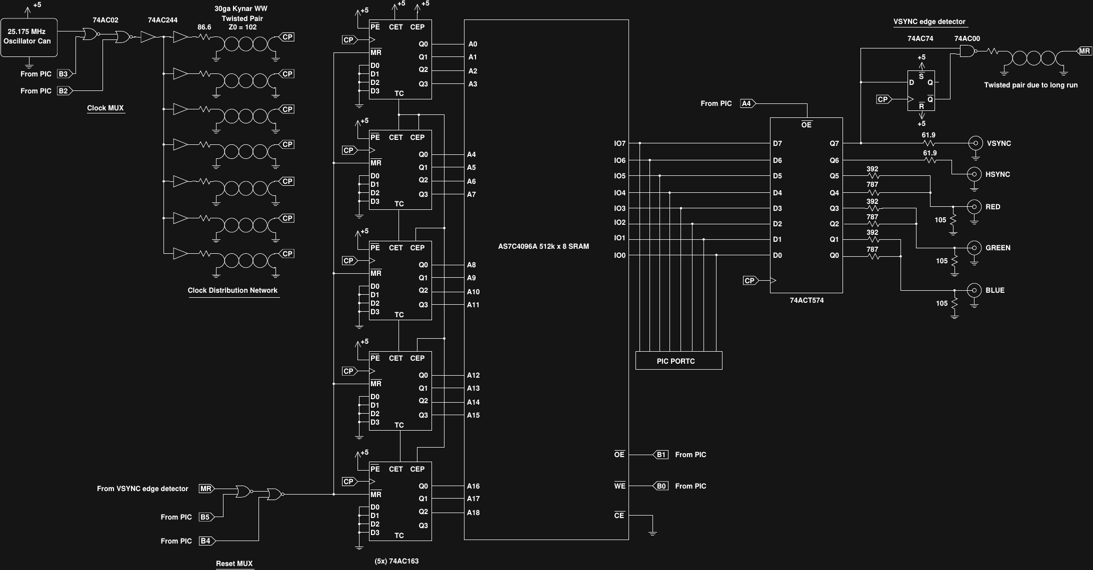
Final Hardware Design
01/03/2017 at 03:09 • 6 commentsHere's the hardware as-built. Click here for a nicer pdf version. It took a few more ICs than I originally thought, but it's still very simple.
![]()
All five waveforms (vsync, hsync, red, green, blue) are stored as a sequence of bytes in a 512k x 8 SRAM; one byte for each pixel clock in the entire frame - blanking intervals and all. Five 74AC163 synchronous binary counters cycle the addresses into the SRAM. The output of the SRAM is latched in a 74ACT574 register - the ACT part is used here since the SRAM has TTL-level outputs. The vsync and hsync signals are output through 61.9 ohm resistors, source-terminating the 75-ohm cables. The color signals are each formed with a simple 3-resistor DAC, providing a total palette of 64 colors, again matched to 75 ohms. Gamma correction is willfully ignored.
I used a 74AC02 quad NOR gate as a pair of MUXes for the clock and reset signals to the counters. When loading data into the SRAM, the PIC bitbangs the clock and reset lines to address sequential locations. After the PIC finishes loading the data, it switches control of the clock and reset lines back to the free-running circuit.
The address reset circuit is fed by a synchronous edge detector (a 74AC74 flip-flop and a 74AC00 NAND gate) that detects the rising edge of the vsync pulse to reset the counter. This arrangement means that the vertical back porch has to be stored first in the SRAM, but this is easily handled by the PIC software.
Finally, since the 74AC logic edges are so fast, and the counters and flip-flops edge sensitive, I took extra care routing the clock signals around the board. The 25.175 MHz dot clock comes from a pre-packaged oscillator "can". I used a 74AC244 octal buffer as a clock-distribution amp, with each of the seven clock lines required on the board driven by a dedicated buffer. To prevent distortions of the clock signals, each line was run with a twisted-pair of wire-wrap wire. These home-brew pairs have an impedance of about 102 ohms, so 86.6 ohm resistors were used to source-terminate each of them at the 74AC244 outputs. The resulting clock signals look good at each of the clocked ICs around the board - this is not the place where you want ringing and possible double-triggering.
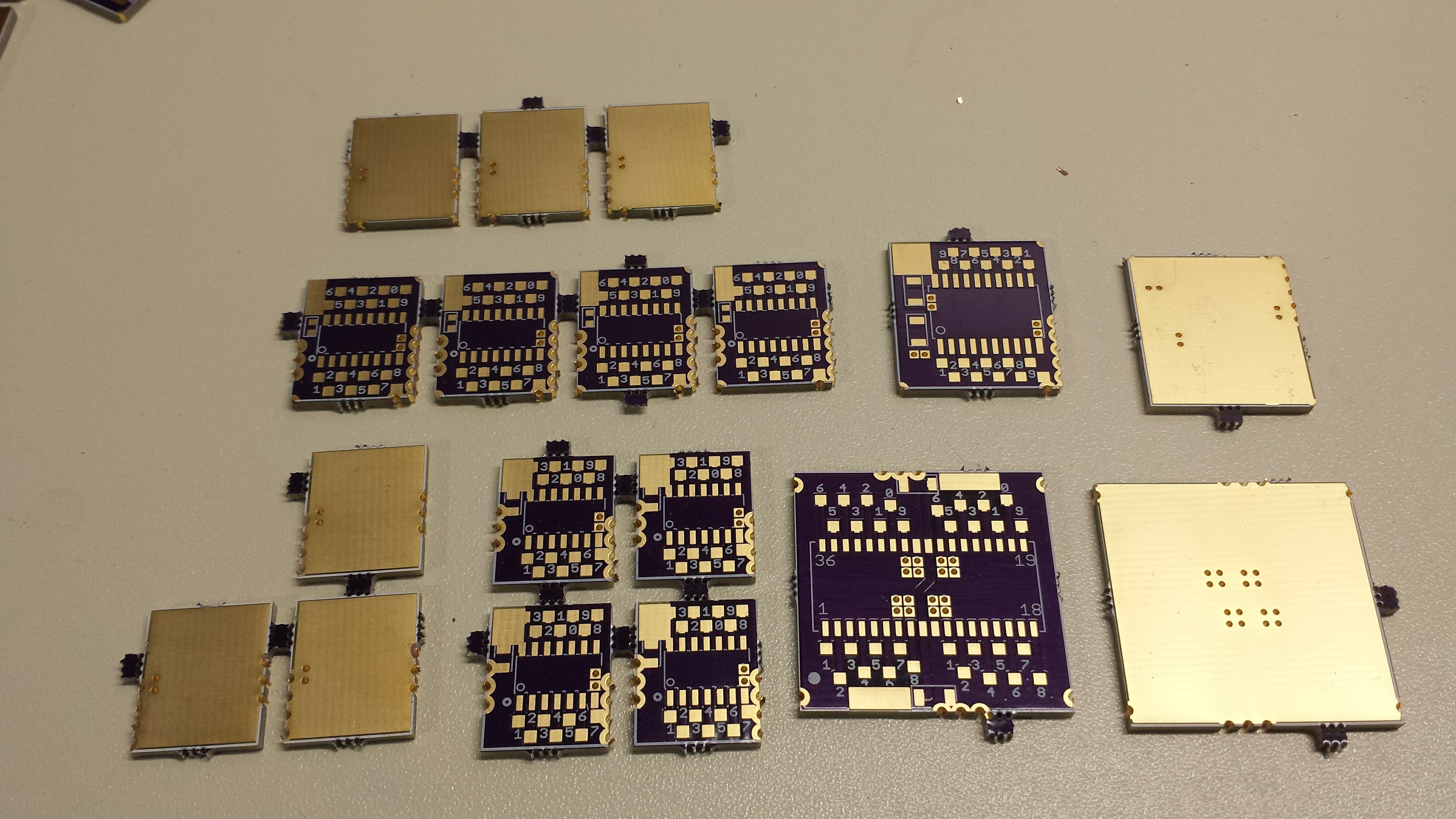
It might not have been obvious from other photos of the board, but most of the ICs are SOIC/SOJ and are mounted on some adapters I designed and had made at OSH Park:
![]()
These worked really well. The pads are spaced out just enough to make soldering manageable. I've soldered directly to SOIC pins before, and I don't like it. Too small. The boards assume the standard corner power pins for logic ICs and include sites for MLCC bypass caps.
Oh, and as for power consumption - when the PIC is calculating the fractals and loading the SRAM, the circuit draws around 19 mA. Once the VGA generation starts, this jumps to 128 mA. Still not too bad, I guess - you could run it off a USB port if you asked the USB host nicely for more than 100 mA.
EDIT 20170103
I updated the schematic to include the CE_bar line on the SRAM, which just gets tied low.
I have also been thinking about the whole clock distribution/twisted pair thing. It might be avoided by using a 74HC gate as the clock driver - with the slower edge rates, maybe you don't need to worry so much about wire lengths. I discussed why 74AC163's were required a few logs ago, but that doesn't mean everything has to be 74AC. If I build another one, this would be an interesting place to try to simplify even more. Maybe a 74HC02 substituted for the 74AC02 could serve as the MUXes and clock driver.
I found a reference that says 74HC edge rates can be as short as 5ns. This is 1.5m of wire at a velocity factor of 1. 1/6 of this length is 25cm. That might make it doable, assuming the rest of the timing still holds.
-
Official Contest Entry Log
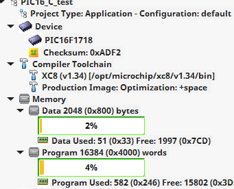
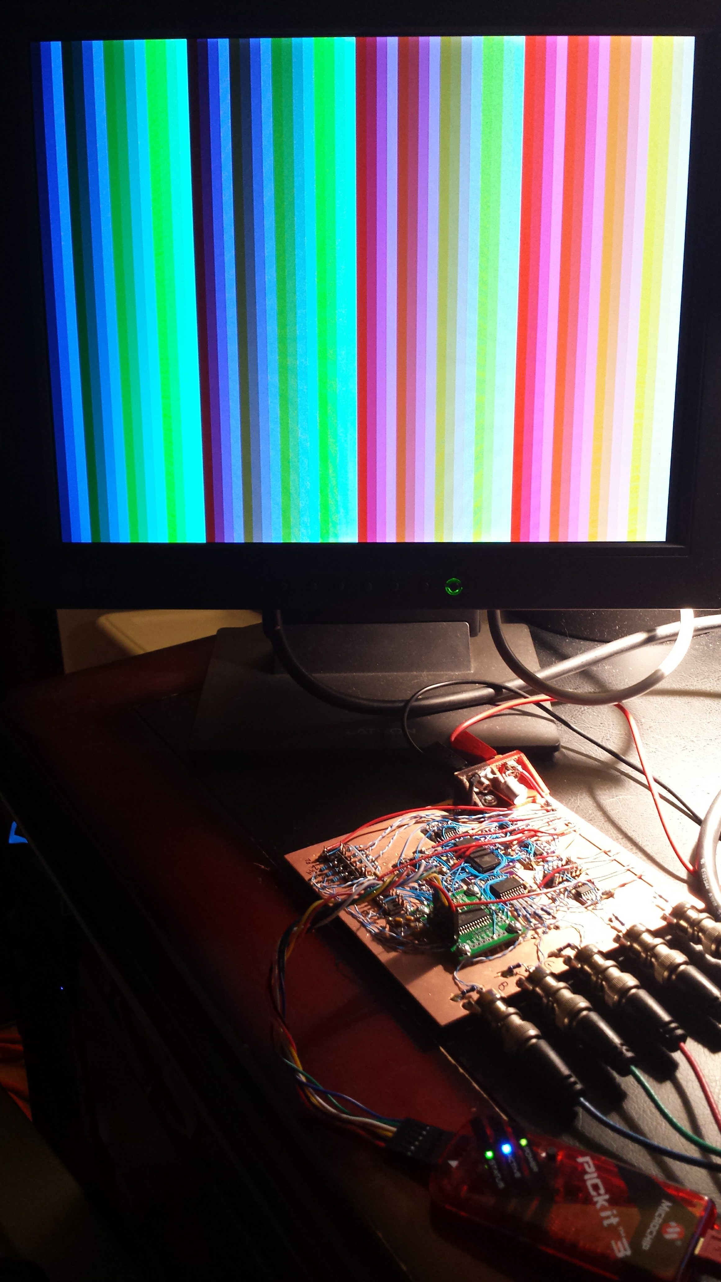
01/02/2017 at 16:27 • 11 commentsOK. I got pretty fractals onto a VGA monitor using 1019 bytes of code on a PIC16F1718. Unless I get something better done by Thursday, I'm going to consider this my contest entry. I let this one run overnight - when I turned on the monitor this morning, here's what I saw:
![]()
The straight C-code takes up 582 14-bit instructions, which is equivalent to 582 * 14 / 8 = 1018.5 bytes.
![]()
The code just fit - actually, as originally written, it was one instruction over. I had to inline the SetupPeriperhals() call to shave off four instructions. Note that this code is compiled with the free Microchip XC8 compiler. The free version tells me that the code could be 232 words smaller if I used the Pro version - you have to wonder how it knows :-)
Yes, writing the whole thing in C is lazy. Perhaps I can redeem myself in the next few days. I did really want to do a hardware project, though. I'll draw up a schematic for the board as-built today for completeness.
Here's the code. I'll upload it as a file, too.
// // vga_test.c - create first VGA frame // #include <xc.h> #include <stdio.h> #include <stdlib.h> #include <stdint.h> #include <pic16f1718.h> // CONFIG1 #pragma config FOSC = INTOSC #pragma config WDTE = OFF #pragma config PWRTE = ON #pragma config MCLRE = ON #pragma config CP = OFF #pragma config BOREN = ON #pragma config CLKOUTEN = OFF #pragma config FCMEN = ON // CONFIG2 #pragma config WRT = ALL #pragma config PPS1WAY = OFF #pragma config ZCDDIS = ON #pragma config PLLEN = ON #pragma config STVREN = OFF #pragma config BORV = LO #pragma config LPBOR = OFF #pragma config LVP = ON // // h/w interface definition // #define REG_OE_bar 0b00010000 #define WE_bar 0b00000001 #define OE_bar 0b00000010 #define CP_en 0b00001000 #define MR_en 0b00100000 #define CP_bar 0b00000100 #define MR_bar 0b00010000 #define VSYNC 0b10000000 #define HSYNC 0b01000000 #define RGB(r, g, b) (((r) << 4) | ((g) << 2) | (b)) #if 0 // manually inlined below to save 4 instructions void SetupPeripherals() { // intosc 32 MHz OSCCON = 0b11110000; // select digital I/O ANSELA = 0; ANSELB = 0; ANSELC = 0; // set TRIS bits: all outputs PORTA = 0x00; TRISA = 0x00; PORTB = 0x00; TRISB = 0x00; PORTC = 0x00; TRISC = 0x80; } #endif // // set control lines for free-running VGA signal generation // void RunMode() { TRISC = 0xff; // data lines all inputs // reset address counter, then let it rip LATB = WE_bar | OE_bar&0 | CP_en&0 | CP_bar&0 | MR_en | MR_bar ; LATB = WE_bar | OE_bar&0 | CP_en&0 | CP_bar&0 | MR_en&0 | MR_bar&0 ; LATA = REG_OE_bar&0; } // // set control lines for bitbanging waveforms into SRAM, and // reset SRAM address counter to 0 // void LoadMode() { LATA = REG_OE_bar; // toggle CP with MR low to reset address counter LATB = WE_bar | OE_bar | CP_en | CP_bar | MR_en | MR_bar ; LATB = WE_bar | OE_bar | CP_en | CP_bar&0 | MR_en | MR_bar ; LATB = WE_bar | OE_bar | CP_en | CP_bar | MR_en | MR_bar ; // bring out of reset LATB = WE_bar | OE_bar | CP_en | CP_bar | MR_en | MR_bar&0 ; TRISC = 0x00; // data lines all outputs } // // bitbang a number of identical bytes into sequential SRAM addresses // void write_SRAM_bytes(uint8_t value, uint8_t count) { PORTC = value; LATB = WE_bar | OE_bar | CP_en | CP_bar | MR_en | MR_bar&0 ; do { // toggle WE to write data LATB = WE_bar&0 | OE_bar | CP_en | CP_bar | MR_en | MR_bar&0 ; LATB = WE_bar | OE_bar | CP_en | CP_bar | MR_en | MR_bar&0 ; // toggle CP to advance address LATB = WE_bar | OE_bar | CP_en | CP_bar&0 | MR_en | MR_bar&0 ; LATB = WE_bar | OE_bar | CP_en | CP_bar | MR_en | MR_bar&0 ; } while (--count); } void GenerateLine(uint8_t vsync, uint8_t rgb, uint8_t count) { do { write_SRAM_bytes( vsync | HSYNC | rgb&0 , 16); // front porch write_SRAM_bytes( vsync | HSYNC&0 | rgb&0 , 96); // sync pulse write_SRAM_bytes( vsync | HSYNC | rgb&0 , 48); // back porch write_SRAM_bytes( vsync | HSYNC | rgb , 200); // video write_SRAM_bytes( vsync | HSYNC | rgb , 200); // video write_SRAM_bytes( vsync | HSYNC | rgb , 240); // video } while (--count); } #define S 12 #define FP(x) ((int16_t)((x) * (1<<S))) //#define WHOLE_SET #ifdef WHOLE_SET #define ASPECT (640./480.) #define WIDTH 2.5 #define IMAG_MIN FP(-1.25) #define IMAG_STEP FP(WIDTH / 480.) #define REAL_MIN FP(-2.5) #define REAL_STEP FP(ASPECT * WIDTH / 640.) #define ESCAPE_RADIUS FP(4.) #define MAXITER 255 #else #define ASPECT (640./480.) #define WIDTH 0.125 #define IMAG_MIN FP(-.0625) #define REAL_MIN FP(-1.5) #define IMAG_STEP FP(WIDTH / 480.) #define REAL_STEP FP(ASPECT * WIDTH / 640.) #define ESCAPE_RADIUS FP(4.) #define MAXITER 255 #endif void GenerateFrame() { GenerateLine( VSYNC , 0, 33); // V back porch int16_t dc = REAL_STEP; int16_t dd = IMAG_STEP; int16_t d = IMAG_MIN; int16_t row = 480; do { write_SRAM_bytes( VSYNC | HSYNC | 0 , 16); // H front porch write_SRAM_bytes( VSYNC | HSYNC&0 | 0 , 96); // H sync pulse write_SRAM_bytes( VSYNC | HSYNC | 0 , 48); // H back porch int16_t c = REAL_MIN; int16_t col = 640; do { int16_t a = 0; int16_t b = 0; uint8_t iter = MAXITER; do { int32_t aa32 = ((int32_t)a * (int32_t)a); if (aa32 & 0xf8000000){ break; } int16_t aa = aa32 >> S; int32_t bb32 = ((int32_t)b * (int32_t)b); if (bb32 & 0xf8000000){ break; } int16_t bb = bb32 >> S; if (aa > ESCAPE_RADIUS || bb > ESCAPE_RADIUS || aa + bb > ESCAPE_RADIUS){ break; } b = (((int32_t)a * (int32_t)b) >> (S-1)) + d; a = aa - bb + c; } while(--iter); uint8_t red, green, blue; red = (iter & 3); green = ((iter & 0x0c) >> 2); blue = ((iter & 0x30) >> 4); write_SRAM_bytes( VSYNC | HSYNC | RGB(red, green, blue), 1); // one pixel c += dc; } while (--col); d += dd; } while (--row); GenerateLine( VSYNC , 0, 10); // V front porch GenerateLine( VSYNC&0 , 0, 2); // V sync pulse write_SRAM_bytes( VSYNC | HSYNC | 0, 2); // end of vsync; resets counter } int main() { // this call inlined here to shave off instructions // SetupPeripherals(); // intosc 32 MHz OSCCON = 0b11110000; // select digital I/O ANSELA = 0; ANSELB = 0; ANSELC = 0; // set TRIS bits: all outputs PORTA = 0x00; TRISA = 0x00; PORTB = 0x00; TRISB = 0x00; PORTC = 0x00; TRISC = 0x80; LoadMode(); GenerateFrame(); RunMode(); while(1){ continue; } return 0; } -
Gamma correction? We don't need no stinkin' gamma correction.
01/02/2017 at 03:50 • 0 commentsIt actually could use gamma correction, but I'm not going to do it. The problem is that the VGA video intensity response curve is non-linear: a hold-over from CRTs. To compensate, the video signal levels need to be be pre-distorted so that the overall system response is linear. Without correction, here's the 64-color palette of the adapter:
![]()
It's not bad, but it would look better corrected. Of course, you can't do this kind of non-linear transform with just a resistor network. I had thought about decoding each 2-bit color component into a 1-of-4 with a 74AC138 decoder, then giving each level it's own resistor, but didn't want to add that much more hardware.
Next, I considered making a non-linear network with resistors and diodes, but thought that color drift with temperature would be a bizarre side-effect.
In the end, I decided to just leave it.
PIC Graphics Demo
Generate 640x480 64-color VGA graphics with an 8-bit PIC and an SRAM framebuffer