Ted Yapo
-
First pixels
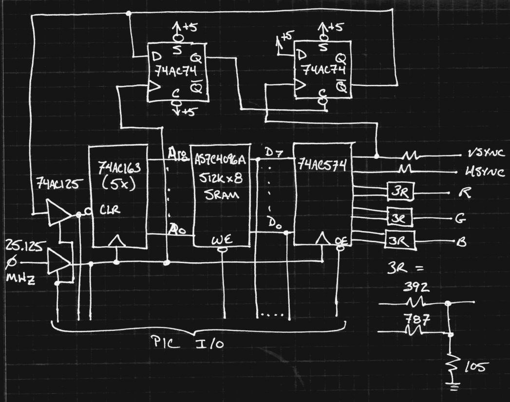
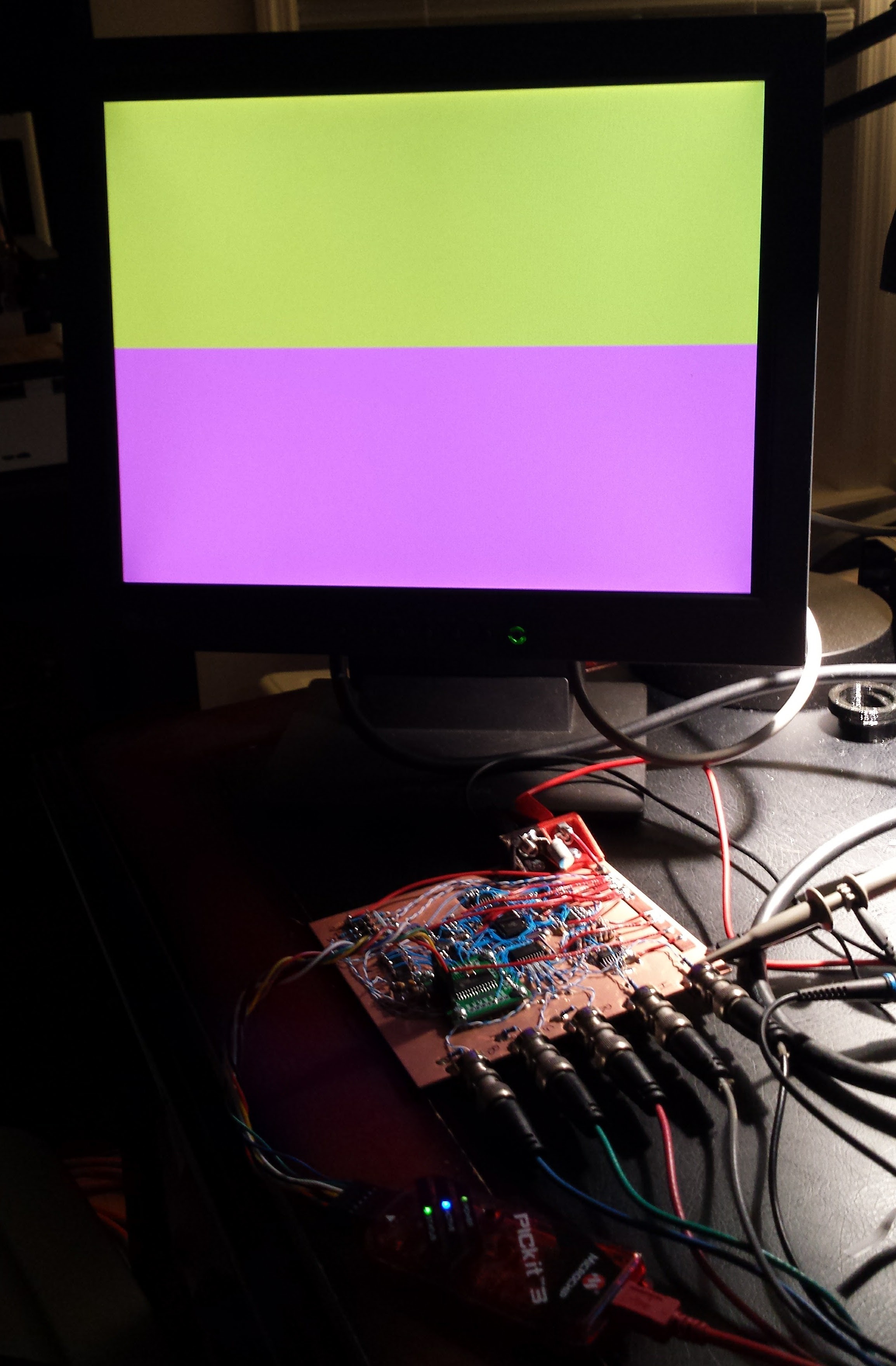
01/02/2017 at 00:02 • 0 commentsAfter a little probing with the scope, I figured out how to program this thing. So far, just big, ugly boring yellow and magenta. I've used 364 bytes of my 1 kB - hopefully there is enough room left to do something cool. I guess I could always move to assembly, too - if I have to...
![]()
The vertical back porch is 80ns longer than it should be due to the way the counter reset logic works - there's essentially a "branch delay slot" at the end of the frame when the counter needs to be reset. Nobody cares if the 1+ ms back porch is off by this much. Otherwise, the 640x480 output should be exactly by-the-book. With some extra code, I could compensate and make the back porch exact, too, but it probably is not worth the effort (and precious instruction space).
I made a few subtle changes to the design as I built it; I'll post a full updated schematic once I put this thing through a few more tests.
Here's the code so far. Mostly bitbanging the SRAM to jam the waveforms in. Now, I have to make something flashy. Maybe I'll play ouside the box a little and use all my 28 kB code space for something cool but not contest-related :-)
// // vga_test.c - create first VGA frame // #include <xc.h> #include <stdio.h> #include <stdlib.h> #include <stdint.h> #include <pic16f1718.h> // CONFIG1 #pragma config FOSC = INTOSC #pragma config WDTE = OFF #pragma config PWRTE = ON #pragma config MCLRE = ON #pragma config CP = OFF #pragma config BOREN = ON #pragma config CLKOUTEN = OFF #pragma config FCMEN = ON // CONFIG2 #pragma config WRT = ALL #pragma config PPS1WAY = OFF #pragma config ZCDDIS = ON #pragma config PLLEN = ON #pragma config STVREN = OFF #pragma config BORV = LO #pragma config LPBOR = OFF #pragma config LVP = ON // // h/w interface definition // #define REG_OE_bar 0b00010000 #define WE_bar 0b00000001 #define OE_bar 0b00000010 #define CP_en 0b00001000 #define MR_en 0b00100000 #define CP_bar 0b00000100 #define MR_bar 0b00010000 #define VSYNC 0b10000000 #define HSYNC 0b01000000 #define RGB(r, g, b) (((r & 0x3) << 4) | ((g & 0x3) << 2) | (b & 0x3)) void SetupPeripherals() { // intosc 32 MHz OSCCON = 0b11110000; // select digital I/O ANSELA = 0; ANSELB = 0; ANSELC = 0; // set TRIS bits: all outputs PORTA = 0x00; TRISA = 0x00; PORTB = 0x00; TRISB = 0x00; PORTC = 0x00; TRISC = 0x80; } // // set control lines for free-running VGA signal generation // void RunMode() { TRISC = 0xff; // data lines all inputs // reset address counter, then let it rip LATB = WE_bar | OE_bar&0 | CP_en&0 | CP_bar&0 | MR_en | MR_bar ; LATB = WE_bar | OE_bar&0 | CP_en&0 | CP_bar&0 | MR_en&0 | MR_bar&0 ; LATA = REG_OE_bar&0; } // // set control lines for bitbanging waveforms into SRAM, and // reset SRAM address counter to 0 // void LoadMode() { LATA = REG_OE_bar; // toggle CP with MR low to reset address counter LATB = WE_bar | OE_bar | CP_en | CP_bar | MR_en | MR_bar ; LATB = WE_bar | OE_bar | CP_en | CP_bar&0 | MR_en | MR_bar ; LATB = WE_bar | OE_bar | CP_en | CP_bar | MR_en | MR_bar ; // bring out of reset LATB = WE_bar | OE_bar | CP_en | CP_bar | MR_en | MR_bar&0 ; TRISC = 0x00; // data lines all outputs } // // bitbang a number of identical bytes into sequential SRAM addresses // void write_SRAM_bytes(uint8_t value, uint8_t count) { PORTC = value; LATB = WE_bar | OE_bar | CP_en | CP_bar | MR_en | MR_bar&0 ; do { // toggle WE to write data LATB = WE_bar&0 | OE_bar | CP_en | CP_bar | MR_en | MR_bar&0 ; LATB = WE_bar | OE_bar | CP_en | CP_bar | MR_en | MR_bar&0 ; // toggle CP to advance address LATB = WE_bar | OE_bar | CP_en | CP_bar&0 | MR_en | MR_bar&0 ; LATB = WE_bar | OE_bar | CP_en | CP_bar | MR_en | MR_bar&0 ; } while (--count); } void GenerateLine(uint8_t vsync, uint8_t rgb, uint8_t count) { do { write_SRAM_bytes( vsync | HSYNC | rgb&0 , 16); // front porch write_SRAM_bytes( vsync | HSYNC&0 | rgb&0 , 96); // sync pulse write_SRAM_bytes( vsync | HSYNC | rgb&0 , 48); // back porch write_SRAM_bytes( vsync | HSYNC | rgb , 200); // video write_SRAM_bytes( vsync | HSYNC | rgb , 200); // video write_SRAM_bytes( vsync | HSYNC | rgb , 240); // video } while (--count); } void GenerateFrame() { GenerateLine( VSYNC , RGB(0, 0, 0), 33); // back porch GenerateLine( VSYNC , RGB(3, 3, 0), 240); // video GenerateLine( VSYNC , RGB(3, 0, 3), 240); // video GenerateLine( VSYNC , RGB(0, 0, 0), 10); // front porch GenerateLine( VSYNC&0 , RGB(0, 0, 0), 2); // sync pulse write_SRAM_bytes( VSYNC | HSYNC | 0, 2); // end of vsync; resets counter } int main() { SetupPeripherals(); LoadMode(); GenerateFrame(); RunMode(); while(1){ continue; } return 0; } -
First hardware bug
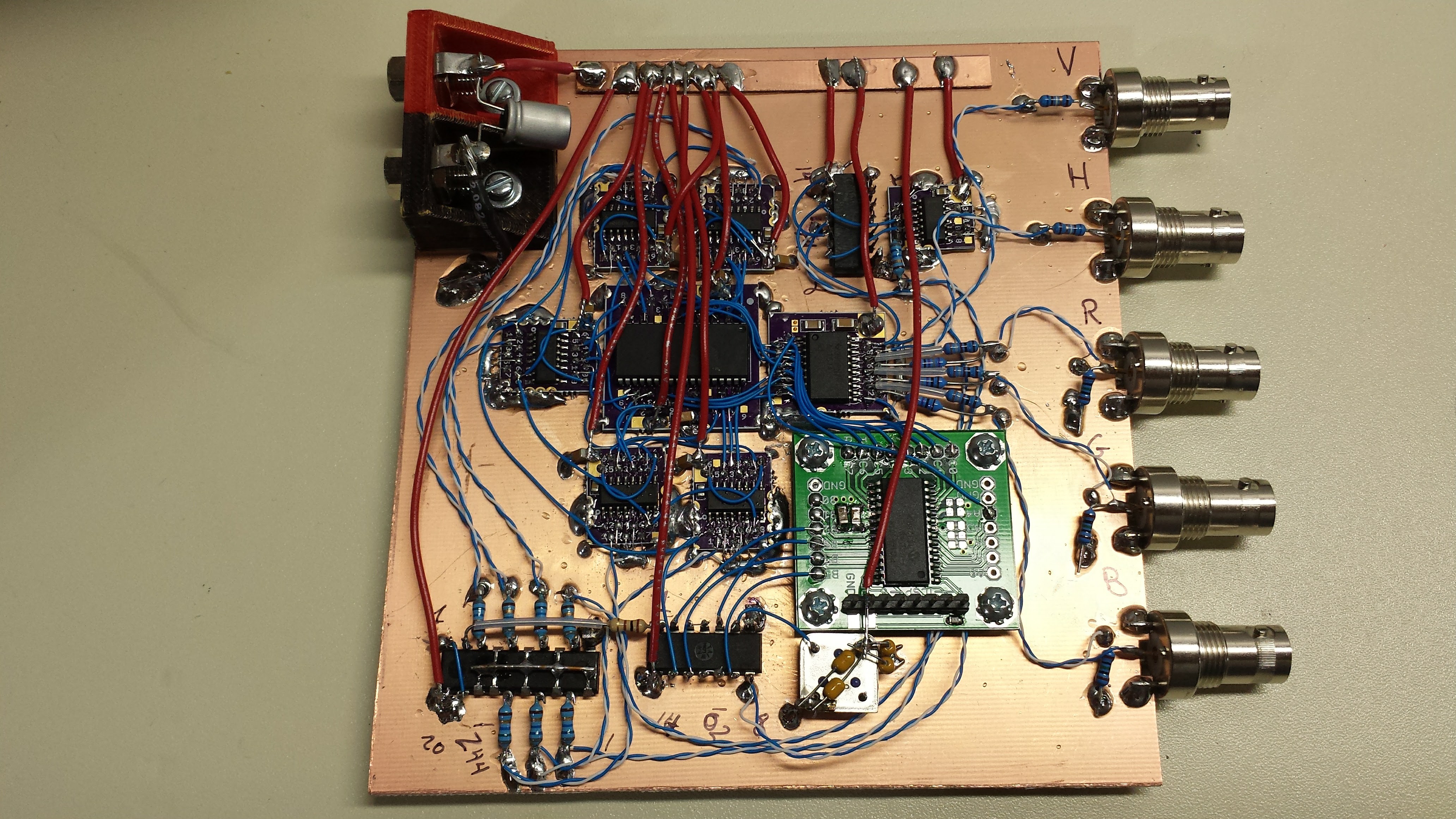
01/01/2017 at 05:03 • 1 commentI finished assembling the board. Even armed with the datasheets for all the IC's, you wouldn't find the bug in this rat's nest:
![]()
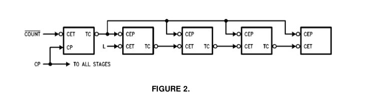
...and that's because the bug is in the 74AC163 datasheet itself! Fairchild was kind enough to include the following diagram in the datasheet:
![]()
See that "L" into the CET input of the second stage? Of course, you're supposed to know that those damn logic guys with their put-useless-bubbles-everywhere habits really mean that you should supply an "H" to the CET input on the chip, because the bubble really isn't there, it's just a convention. Just like the useless bubbles on the output of TC and input of CEP - you're supposed to ignore those and just wire TC to CEP, not wire two inverters external to the chip.
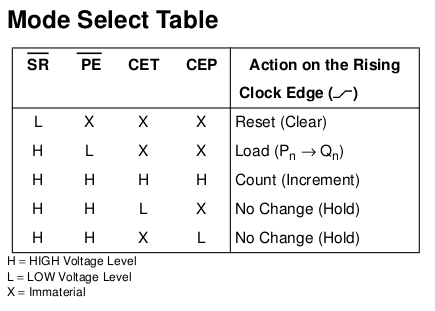
The whole mess is clarified by the supplied table:
![]()
here, it's easy to see that everything needs to be high for the count to proceed.
Once I fixed that, I got the counters running well at 25.175 MHz. So far it looks pretty good - the MSB transition is within a few nanoseconds of the LSB, and the twisted-pair clock distribution scheme seems to give nice clock signals at each of the seven IC's that require it.
Now, it's software time again.
EDIT 20170101
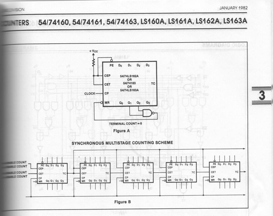
Contrast the above diagram with this one I scanned from my copy of the Signetics TTL Logic Data Manual 1982:
![]()
Much clearer - I could have even understood it at age 12, when this was printed :-)
-
One last log for 2016
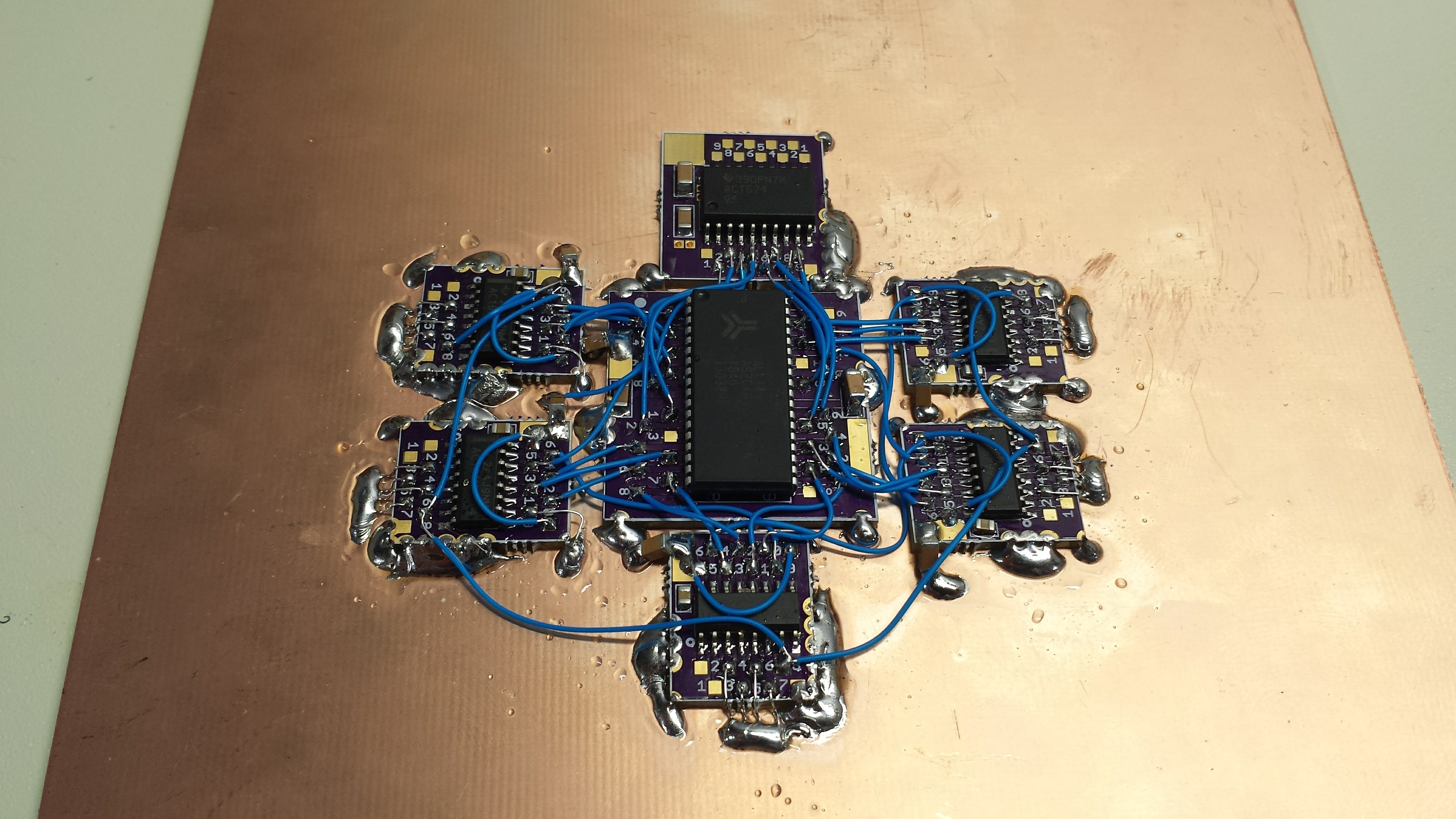
12/31/2016 at 22:30 • 0 commentsI started building the VGA generator hardware yesterday. The main ICs are all SOIC (and SOJ for the SRAM), so I had some adapter boards made to mount over a solid ground plane. The adapters all have bare copper (gold) on the back, and I thought about reflowing them to the plane, but I ended up just soldering down the castellations on the edges. Hopefully, this will be good enough.
![]()
The center IC is the 512k x 8 SRAM, and the five 74AC163 address counters are in the outside ring to minimize the wire length. The 74AC574 output latch is at the top. Obviously more to build, but it's a start. I haven't run the power buses yet - there are 0.1 uF and 10 uF MLCCs at each IC so I think I can be somewhat casual with the 5V supply wiring.
I finally bought a copy of High Speed Digital Design: A Handbook of Black Magic which I have been meaning to read forever. I found an "international" paperback edition for less than $25. To comply with the warning label on the back, I only read it when I am in India, Bangladesh, Pakistan, Nepal, Sri Lanka, the Maldives, or on Tralfamadore.
At any rate, the book covers why this thing might not work - if the edge rates of the 74AC logic are fast compared to the wire lengths. I have read that the 74AC gates have rise times of 2ns, but I measured them at 1.15 ns here on my 300 MHz scope, which is really, really close to the rise time of the scope itself. In a cable with velocity factor 1, the edge would cover about 35cm of wire; a conservative design might treat any wires less than about 1/6 of this ( = 6 cm) as transmission lines, and terminate them appropriately. Even for wires shorter than this, inductance of the line combined with the capacitance of the receiving gate can cause ringing and signal problems.
I've decided to take a chance with unterminated wires for the address lines - they're only 1 or 2 cm at most, and fairly close to the ground plane. I'm guessing they're OK. The two really critical signals on the board are clock and reset - for these, I'm going to run twisted-pair lines to each counter from dedicated 74AC244 buffers, and source-terminate the drivers.
I made some twisted pair with 30ga kynar wire-wrap wire, and measured it's impedance at around 102 ohms with a simple time-domain-reflectometer setup. (I also measured the capacitance of a section of line, then shorted one end and measured the inductance - this gave 107 ohms - close enough). If I source-terminate these lines, I should be able to make the clock wires as long as I need.
The one thing I'm not sure about is the TC outputs from counter to counter - the long wires seen above. These aren't edge-triggered, so reflections should not be a problem as long as ringing has died down before the next clock edge. If I have to, I can replace them with sections of twisted pair, or maybe just replace each wire with a 100-ohm resistor to damp any ringing.
There's still a lot of work to do on this board, but I got it started, at least.
-
Future Work: Address Reset the Right Way
12/12/2016 at 19:26 • 0 commentsI'm going to document a few places where I'm consciously cutting corners on the design. Here's the first issue - my one-shot circuit for resetting the address counter on the rising edge of Vsync is a poor design. I think it will work, but it's not done "the right way," and that bugs me. I think this is how it should be done:
![]()
In this design, the previous state of the vsync line is always stored in the flip-flop (the '574 and the '74 form a 2-stage shift register). The rising edge of the vsync line is detected with the NAND gate (74AC00, but unlabeled in the diagram). This would mean an extra gate package on the board for the NAND, which I'm reluctant to do (simplify!). Of course, if I have to, I can always switch over to this design.
It might be possible to simplify this even more by using input to the 74AC574 and the output to create the reset signal - this design is back to one package (a 74AC00 quad NAND).
![]() The problem with this design is that the SRAM drivers are already looking like they might be a problem (more details in a future log - they're TTL-level outputs, and not very strong ones, either). Once I get the driver issues sorted out (either with a 74ACT574 with TTL thresholds, or a Thevenin resistive termination/pullup combination on the 74AC574 inputs), I can re-evaluate if this design makes sense. It does only use one gate package - in fact, two gates are left over.
The problem with this design is that the SRAM drivers are already looking like they might be a problem (more details in a future log - they're TTL-level outputs, and not very strong ones, either). Once I get the driver issues sorted out (either with a 74ACT574 with TTL thresholds, or a Thevenin resistive termination/pullup combination on the 74AC574 inputs), I can re-evaluate if this design makes sense. It does only use one gate package - in fact, two gates are left over.Next Up
Gamma correction: The Right Way, The Wrong Way, and what I might end up doing
-
First PIC16 Fractals
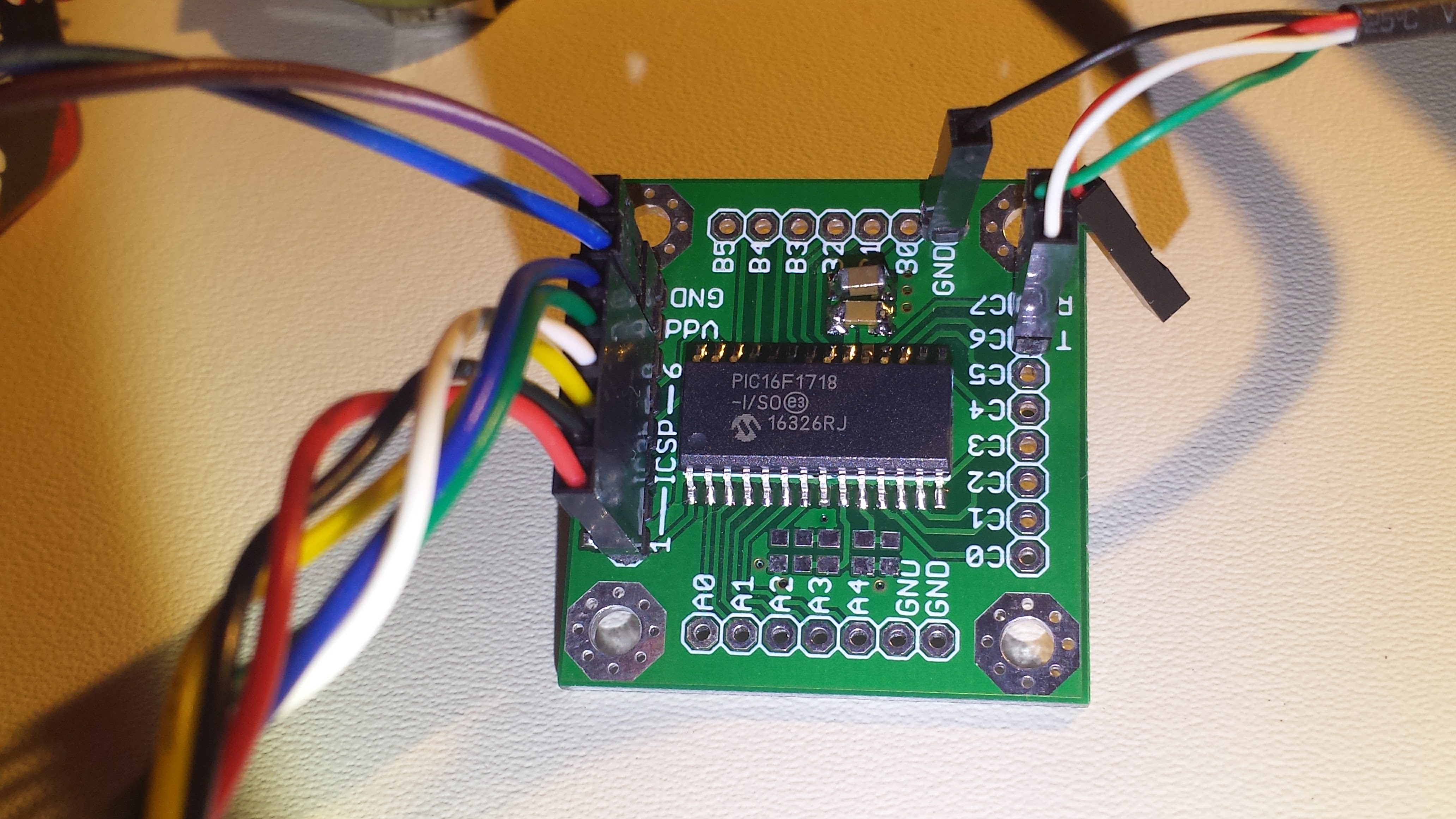
12/12/2016 at 01:29 • 1 commentMy PIC16F1718's came in a recent DigiKey box; I was very happy to realize that they're pin-compatible with the PIC16F723A, for which I had a bunch of breakout boards made a while ago. All the purple ones are used up, so I had to mount it on a green one:
![]()
I ignored the crystal site on the board and instead decided to run this one on the internal 32 MHz oscillator. I don't have the proto-boards for the VGA interface yet, so I began by sending generated pixels over the UART to be collected into an image with a small python program on a PC.
The PIC16F1718 uses 14-bit instructions, so 585 of them fit into 1 kB. I was able to get a basic Mandelbrot set generator in 476 instructions using straight C-code. This was really convenient, because it allowed me to do the code development on a PC, where the program runs in about a hundred milliseconds (wall-clock time). On the PIC, the code took 1 hour and 45 minutes :-) A lot of this time is wasted on transferring pixels over the serial port, which I could only get going reliably at 19200 baud, possibly due to the tolerance of the internal oscillator. The transmission overhead could be improved significantly, but there's no point, because the UART won't be used in the final system.
The output is almost as expected, although some last-minute experiments in optimization flipped the coordinate system - this is easily fixed. Again, I'm saving color output for the final system with the VGA interface hardware.
![]()
When the hardware is ready, I'll need to add code to initialize the video SRAM and write the pixels in - I'm confident this will all fit, since I have 109 more instructions to play with, and this has all been done with the inferior free version of the XC8 compiler. A 60-day trial of the pro version would undoubtedly shrink the code, and I could always move to assembly if required.
So far, the center and zoom of the image are hard-coded. I'm considering adding a zoom knob and pan controls with simple potentiometers connected to a few analog input pins. Theoretically, it could be considered interactive, if you don't mind waiting two hours between renderings.
Ray Tracing Progress
I'm a few days into assembly experiments to create a vector math library I can use to implement a ray-tracer. I have a version running in C on the PC, and it probably isn't possible in C in 585 instructions on this PIC. Even the assembly version won't be easy to fit, but it's fun to think about, and I have the fractals as a backup plan. We shall see how it turns out.
PIC Mandelbrot Code
Here's the c-code for the fractal generator. It uses 16-bit fixed-point math, and a klunky serial handshake sequence to send pixels to the PC, but it works. I haven't tried to optimize it yet, because it fit as-is.
/* * File: pic1718_bringup.c * Author: tyapo * * Created on December 6, 2014, 7:37 PM */ #include <xc.h> #include <stdio.h> #include <stdlib.h> #include <stdint.h> #include <pic16f1718.h> // CONFIG1 #pragma config FOSC = INTOSC #pragma config WDTE = OFF #pragma config PWRTE = ON #pragma config MCLRE = ON #pragma config CP = OFF #pragma config BOREN = ON #pragma config CLKOUTEN = OFF #pragma config FCMEN = ON // CONFIG2 #pragma config WRT = ALL #pragma config PPS1WAY = OFF #pragma config ZCDDIS = ON #pragma config PLLEN = ON #pragma config STVREN = OFF #pragma config BORV = LO #pragma config LPBOR = OFF #pragma config LVP = ON void SendByte(uint8_t b) { while(!TRMT){ continue; } TXREG = b; } void SendPacket(uint16_t row, uint16_t col, uint8_t iter) { // SendByte( 255 ); SendByte( (row & 0xff00) >> 8 ); SendByte( (row & 0x00ff) >> 0 ); SendByte( (col & 0xff00) >> 8 ); SendByte( (col & 0x00ff) >> 0 ); SendByte( iter ); } typedef enum { BAUD_RATE_300, BAUD_RATE_1200, BAUD_RATE_2400, BAUD_RATE_4800, BAUD_RATE_9600, BAUD_RATE_19200, BAUD_RATE_38400, BAUD_RATE_57600, BAUD_RATE_115200, BAUD_RATE_230400, BAUD_RATE_384000, BAUD_RATE_576000, BAUD_RATE_1152000 } BaudRate_t; void SetBaudRate(BaudRate_t rate){ // wait for any outgoing packet to finish while(!TRMT){ continue; } // disable RX/TX during baud rate change CREN = 0; TXEN = 0; switch(rate){ case BAUD_RATE_300: BRG16 = 1; BRGH = 0; SPBRG = 6666; break; case BAUD_RATE_1200: BRG16 = 1; BRGH = 0; SPBRG = 3332; break; case BAUD_RATE_2400: BRG16 = 1; BRGH = 0; SPBRG = 832; break; case BAUD_RATE_9600: BRG16 = 1; BRGH = 0; SPBRG = 207; break; case BAUD_RATE_19200: BRG16 = 1; BRGH = 0; SPBRG = 103; break; case BAUD_RATE_57600: BRG16 = 1; BRGH = 0; SPBRG = 34; break; } // configure AUSART RX/TX TXEN = 1; // TX CREN = 1; // RX } void SetupPeripherals() { // intosc 32 MHz OSCCON = 0b11110000; // configure PPS for EUSART RXPPS = 0b00010111; // RC7 for RX RC6PPS = 0b00010100; // RC6 for TX // configure AUSART for aynch operation SYNC = 0; SPEN = 1; ANSELC = 0; //SCKP = 0; SetBaudRate(BAUD_RATE_19200); // configure EUSART for TX/RX TXEN = 1; CREN = 1; // set TRIS bits PORTA = 0x00; TRISA = 0x00; PORTB = 0x00; TRISB = 0x00; PORTC = 0x00; TRISC = 0x80; } #define S 12 #define FP(x) ((int16_t)((x) * (1<<S))) #define ASPECT (640./480.) #define WIDTH 2.5 #define IMAG_MIN FP(-1.25) #define IMAG_STEP FP(WIDTH / 480.) #define REAL_MIN FP(-2.5) #define REAL_STEP FP(ASPECT * WIDTH / 640.) #define ESCAPE_RADIUS FP(4.) int main() { SetupPeripherals(); #if 0 int16_t row = 480; do { int16_t col = 640; do { // wait for rx'd byte to sync while (!RCIF) { continue; } SendByte(RCREG); SendPacket(row, col, 127); } while (--col); } while (--row); #else int16_t dc = REAL_STEP; int16_t dd = IMAG_STEP; int16_t d = IMAG_MIN; int16_t row = 480; do { int16_t c = REAL_MIN; int16_t col = 640; do { int16_t a = 0; int16_t b = 0; uint8_t iter = 0; while(iter++ < 254){ int32_t aa32 = ((int32_t)a * (int32_t)a); if (aa32 & 0xf8000000){ break; } int16_t aa = aa32 >> S; int32_t bb32 = ((int32_t)b * (int32_t)b); if (bb32 & 0xf8000000){ break; } int16_t bb = bb32 >> S; if (aa > ESCAPE_RADIUS || bb > ESCAPE_RADIUS || aa + bb > ESCAPE_RADIUS){ break; } b = (((int32_t)a * (int32_t)b) >> (S-1)) + d; a = aa - bb + c; } c += dc; // wait for rx'd byte to sync while (!RCIF) { continue; } SendByte(RCREG); SendPacket(row, col, iter); } while (--col); d += dd; } while (--row); #endif return 0; } -
VGA Generator Design
12/06/2016 at 02:57 • 17 commentsSo, I think the VGA generator design is complete - enough so that I ordered components and adapter boards for the SMD parts:
![]()
The 19-bit address for the SRAM is generated by (5) 74AC193 synchronous counters. The reset circuit was an interesting one to design - the address resets to zero on the rising edge of VSYNC, using an edge-triggered 74AC74 d-flop to hold the counter clear line until the next clock edge - the '163 has a synchronous reset. On the same edge, a second d-flop clears the first one to prevent another reset until the next posedge of VSYNC. This edge-triggered reset is required because the vertical sync line is high (also low, for the actual sync pulse) for a number of dot clocks per frame.
This arrangement means the data has to be rotated in the SRAM address space a little, but that's just some PIC code.
A pair of 3-state buffers (74AC125) multiplex the counter clock and reset lines between the generator circuitry and the PIC. On the data lines, the SRAM already has 3-state outputs. In total 13 I/O lines from the PIC are required. The PIC doesn't connect the address lines directly - it has to reset and increment the counter to access the RAM. I'm willing to accept this since it saves multiplexing 19 lines.
The clock multiplexing is asynchronous - so there could be a runt pulse generated when the PIC first enables the VGA output, but if it holds the reset line until after the clock is established, this should cause no harm.
I ordered a PIC16F1718 as a candidate processor - it has 2 kB of RAM, which might come in handy, and the rest of the niceties of the modern mid-level PICs. I chose this one because it looks like it will drop right in to some development boards I made for the older PIC16F723A's, which would be very convenient.
I designed some ugly-smd adapters for all these (SOIC) parts. I figure it will be a good test of the prototyping system to see if it can run at 25 MHz. Worst case, I'll wire all the signals with 30-gauge kynar twisted pairs (100 ohms impedance) with series terminations right on the adapter boards. It probably won't be necessary.
Overall, it's 8 ICs plus the RAM (and the PIC, which could be any microcontroller with 13 I/O lines). I think I initially said 5, meaning 10, so it's basically what I thought :-)
UPDATE 20161206
Since I'm only using two of the four 3-state buffers in the 74AC125 package, I might try adding the remaining two in parallel to make "super drivers". These are the lines with the greatest fanout (7 for CLK and 4 for CLR), so a little extra drive probably won't hurt.
Also, instead of a too-clever sequencing solution to switching over control of the CLR line, I'll add a weak pullup to hold the state while control is switched over. I read on Wikipedia that this is done on PCI buses.
-
Ripple Counters II
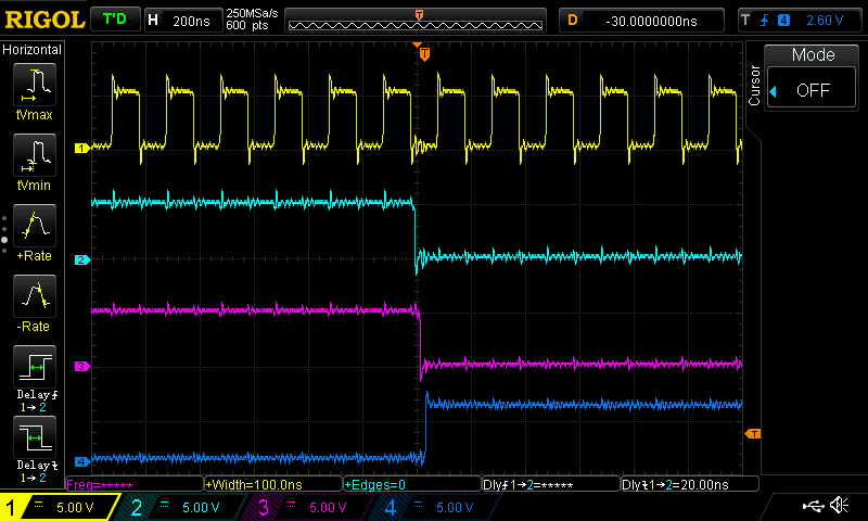
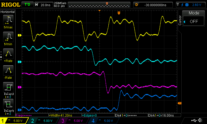
12/05/2016 at 13:48 • 3 commentsI found a bag of 74HC4020s in my stash. It's a 14-stage ripple counter with two outputs missing - kind of a bizarre part, if you ask me. I hooked the clock input to a signal generator, and outputs Q0, Q4, Q8, and Q13 to the scope. Here it's at 10 MHz, triggered on the transition of Q13, the MSB - all the lower bits are going low, while Q13 goes high:
![]()
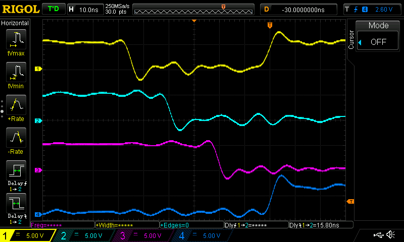
You can see a bit of delay between the successive stages. Zooming in, it's easy to measure:
![]()
All those wiggles are poor layout (a solderless breadboard) and bad probing (long wires attached to the scope probes). Inside the time cursors, the output lines aren't showing the correct count - it's only after the last (blue) transition that the outputs are correct. The delay from Q0 to Q13 is 56ns - so, during that time, the outputs are wrong. But this counter will typically run at 100+ MHz - how can that be?? Let's turn up the frequency. At 18 MHz, Q0 is now transitioning to its next state before Q13 finishes the last:
![]()
At this frequency, there's no longer any point in time at which the outputs show the correct count for this state. The state still gets updated correctly, and if you stopped the clock at the trigger point (mid-screen), the output lines would settle into the correct state, but you couldn't use this counter to generate successive values at this frequency.
The generator I was using only goes up to 25 MHz, and there you can see that things just get progressively worse - you're almost missing two states now:
If I really wanted a nasty hack in this project, I'd cut sections of cheap RG59 coax to the exact lengths to equalize the delay between the bits of these counters. At 1ns/foot with a 66% velocity factor, I'd only need 40 feet of cable for that first bit, with progressively shorter cables for the higher bits. It's almost like the kind of stuff you find in classic oscilloscopes. Still, easier just to buy a few synchronous counters.![]()
-
Simulating Fixed Point
12/05/2016 at 01:36 • 0 commentsI want to do some graphics on a PIC - so I need some "real" datatypes. But I'm not sure how many bits of fixed-point resolution I need. It's easy enough to code up fixed-point routines for any multiple of 8 bits, but I'd rather just do it once. So, I wrote some templated C++ code to simulate fixed-point types. Here's a 640x480 Mandelbrot set in 3.5 8-bit fixed point math (generated on a PC):
![]()
Not great. I knew I'd need more than 8-bits, though :-) Here's the same in 3.13 16-bits:
![]()
Much better. Of course, if you zoomed in, you'd need more bits of precision. You can test 24, 32, 40, 48, 56, or 64-bits with my trivial C++ class below. I started testing with fractals, because the algorithm is so simple: in my teens, I got it published as an Apple II BASIC one-liner in Nibble magazine. Anyway, templated over the datatypes, it looks like this:
template <typename iter_t, typename real_t>
iter_t
mandelbrot_test(real_t c, real_t d, iter_t max_iter, real_t max_mag)
{
  real_t a, b;
  a = real_t(0.);
  b = real_t(0.);
  iter_t i = 0;
  while (i < max_iter){
    real_t aa = a * a;
    real_t bb = b * b;
    if (aa + bb > max_mag){
      break;
    }
    b = real_t(2.) * a * b + d;
    a = aa - bb + c;
    i++;
  }
  return i;
}
This is a direct translation of the floating-point algorithm; it could be improved some to avoid issues with fixed-point overflows.
So far, I've only implemented addition, subtraction, and multiplication, which is sufficient for these fractals:
template <int width, int scale>
class fixed_pt
{
public:
  fixed_pt(int64_t val = 0)
    : w(width),
      s(scale),
      v(val)
  {
  }
  fixed_pt(double x)
    : w(width),
      s(scale)
  {
    v = int64_t((x * (int64_t(1) << w))) >> s;
    if (x >= 0){
      v &= 0xffffffffffffffffull >> (64-w);
    } else {
      v |= 0xffffffffffffffffull << (64-w);
    }
  }
  operator double()
  {
    return v / double(int64_t(1) << (w-s));
  }
  friend fixed_pt operator+ (fixed_pt<width, scale> a, fixed_pt<width, scale> b)
  {
    return fixed_pt<width, scale>(double(a) + double(b));
  }
  friend fixed_pt operator- (fixed_pt<width, scale> a, fixed_pt<width, scale> b)
  {
    return fixed_pt<width, scale>(double(a) - double(b));
  }
  friend fixed_pt operator* (fixed_pt<width, scale> a, fixed_pt<width, scale> b)
  {
    return fixed_pt<width, scale>(double(a) * double(b));
  }
private:
  int64_t v;
  int w;
  int s;
};
Yes, it's a hack - meant in the worst pejorative sense - but it was easy to implement, and will give me some quick results without having to dive into embedded issues yet. Once I decide on the number of bits I need, I can start coding up some routines - I know I'll need at least these operations.
I'll also need division if I want to get ray-tracing going. Square roots are probably also necessary, and those can be implemented in terms of the other operations - they might not be fast, but who cares?
I didn't implement any colors here: I'm saving that for the embedded code :-)
Now, I can try some ray-tracing. That will take a little more time...
EDIT
So, I really should have done this first, but I was pretty sure of the answer. I just compiled the most bare-bones calculation of the above fractal in C using Microchips XC8 compiler, a PIC16 target, and "float" datatypes: 1565 instructions = 2738.8 bytes. Yeah, you can't just take the easy way.
-
I Hate Ripple Counters
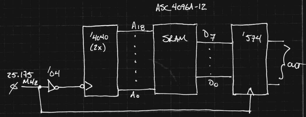
12/03/2016 at 20:55 • 16 commentsSo, what the heck, I'll look at timing before slapping something together. Here's a simplified schematic of the guts of the VGA framebuffer (it ignores the reset and connections between the two '4040's required to generate 19 bits of address). The dot clock is 25.175 MHz, for a period of about 39.7 ns.
![]()
Looks simple, right? I started with 74HC logic - the 74HC4040 has a typical count frequency of 90 MHz, which sounds plenty fast. In the schematic above, the '4040 counters increment the address on the rising edge of the clock, while the '574 d-flop captures the data from the last address before it changes. I'm going to ignore those timing calculations for the moment (next log) because there's an even bigger problem here - it takes too long for the address to settle. The AS7C4096A-12 SRAM has a 12 ns access time, so the addess has to be stable within about 39-12 = 27 ns to work (ignoring setup time for the output register).
In the 74HC4040 datasheet, it specifies a tpd from CP to Q0 of 14 ns (typ at 5V). I'm using typical values for the moment; if it doesn't work there, it's not going to work worst-case, either. It further specifies the tpd from Qn to Qn+1 as 8 ns. Since it's a ripple counter, Q0 flips, then Q1, then Q2, etc, so we have to add all the delays so see how long it takes for the address to settle to the next value. When all of the bits have to change state, it takes 14 + 11 * 8 = 102 ns for the output lines to show the correct address - that's way too long, since we have less than 40ns to get the next byte of data out. This also ignores the fact that two 74HC4040s need to be chained to generate the 19-bit address: in that case, we're looking at 14 + 11*8 + 14 + 6*8 = 164 ns for all the address bits to settle.
VHC to the rescue?
I haven't used VHC logic before, but keep seeing it around. Surely the 74VHC4040, with its 210 Mhz typical max clock frequency will do the job! Let's run the numbers, using a 15pF load : tpd (CP to Q0) = 4.8 ns, and tpd (Qn to Qn+1) = 1.6ns. So, with two of them connected to generate 19 bits of address, the tpd from the clock edge to the MSB settling is: 4.8 + 11*1.6 + 4.8 + 6*1.6 = 36.8 ns. Add in the 12 ns access time of the SRAM, and we're definitely over budget.
It's a shame, because the '4040 packs 12-bits into a single package. I have to go take them out of my shopping cart now :-)
What about the '393 counters?
The 74VHC393 is another candidate - it has twin 4-bit counters in a package, so three ICs would be necessary. I started with the VHC part this time :-) In this case, the propagation delays are specified for each of the four bits. For Qd (the fourth bit), the typical tpd is given as 8.5ns (assuming a 15pF load), and the Qc tpd is 7.7 ns (the third bit). With five counters chained, the typical time to get the 19th bit settled is 4*8.5 + 7.7 = 41.7 ns. Nope.
Synchronous Counters
Synchronous counters use extra logic to form the next state from the previous one directly, without waiting for clocks to ripple through, so the outputs settle faster. The disadvantage is that they seem to only be available in 4-bits/package. Now, I need 5 ICs to make the counter - if it's even fast enough. The 74VHC163 claims 185 MHz at 5V - maybe that will work. Interestingly, it also has a synchronous clear, and connections for synchronous expansion between counters with lookahead carry outputs. If I'm reading the datasheet correctly, the maximum delay from clock edge to valid outputs is 10.1 ns (at 5V) - even expanded to 20 bits. This would work - with the 12ns SRAM access time, still way under the 40ns cycle time.
How about the 74HC163? 74HC parts aren't specified at 5V for some strange reason, but at 6V, the tpd (max) is 35 ns, and at 4.5V it's 41 ns. Doesn't look promising - although the typical 21ns (6V) or 25ns (4.5V) sound workable.
If I were going to build a bunch of these, I'd try harder to get the 74HC163 to work. Since I'm only building one, and on a deadline, I'll spring for the more expensive 74VHC163s. I need 5 of them, which sucks.
The clock input on the '163 works on the positive edge, so the schematic above changes a bit, but at least the addresses seem OK. Next step - the rest of the logic and timing calculations.
Did I miss something on the ripple counters? Maybe I'm doing this wrong?
This is where a little CPLD would be nice - but that would count against my 1kB ;-)
PIC Address Generation?
What about using the fastest PIC available and bitbanging the address lines? The fastest ones I can find are 64MHz, or 16 MIPS. Even if you could output a new address every cycle, that's still only about half of the 25.175 MHz clock required. Maybe a fast external counter for the lowest 4 (or 8) bits, and the PIC generates the upper ones? Synchronization is an issue, but it's worth thinking about - maybe if the PIC runs from the external 25.175 MHz clock, and synchronizes itself with the external low-bit counter(s)? This could be interesting.
-
Simpler VGA Interface
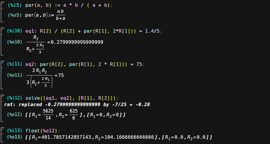
12/02/2016 at 03:54 • 0 commentsFive resistors seemed like too many for a 2-bit DAC (pun intended). R/2R ladders are useful because they can provide many bits using the same R's - with fewer bits, binary-weighted R's work fine. So, here's the update:
![]()
The LSB uses twice the resistance of the MSB. When both lines are at 5V, the output should be 1.4V. The output impedance should be 75 ohms. Again, two equations, two unknowns, and one computer algebra program:
![]()
The resistor values aren't that close to standard values, but 390 is good for R1 (factoring in the 12 ohms of the output driver), and 100 might do for R2. 2R1 might be 750 or 820. Or I could break down and buy some E96 values- 105, 390, and 787 would be overkill, but they're available.
PIC Graphics Demo
Generate 640x480 64-color VGA graphics with an 8-bit PIC and an SRAM framebuffer

 The problem with this design is that the SRAM drivers are already looking like they might be a problem (more details in a future log - they're TTL-level outputs, and not very strong ones, either). Once I get the driver issues sorted out (either with a 74ACT574 with TTL thresholds, or a Thevenin resistive termination/pullup combination on the 74AC574 inputs), I can re-evaluate if this design makes sense. It does only use one gate package - in fact, two gates are left over.