-
1Disassemble garden lights
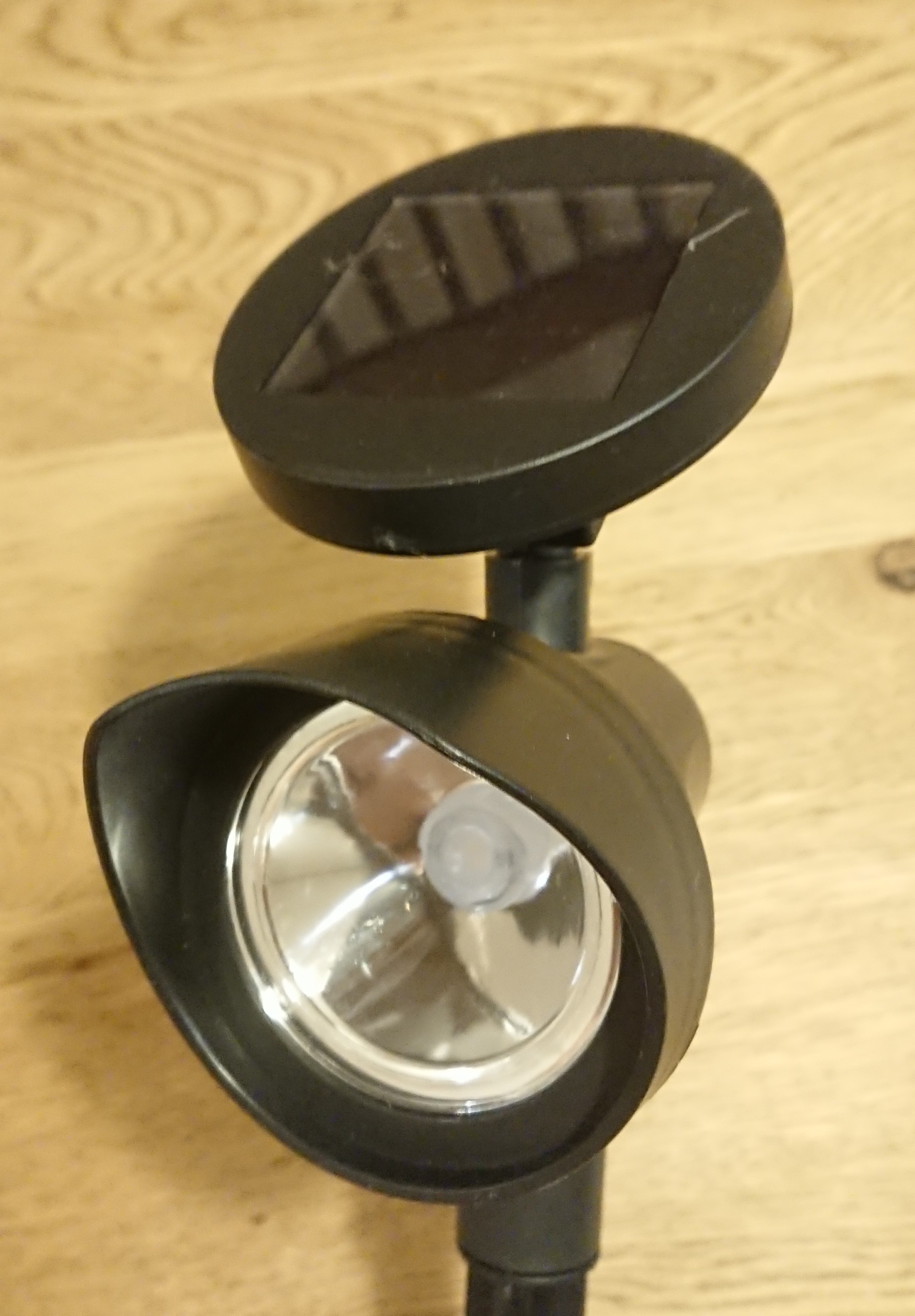
Disassemble the solar panel section at the top of the garden light, which contains the battery and circuit board.
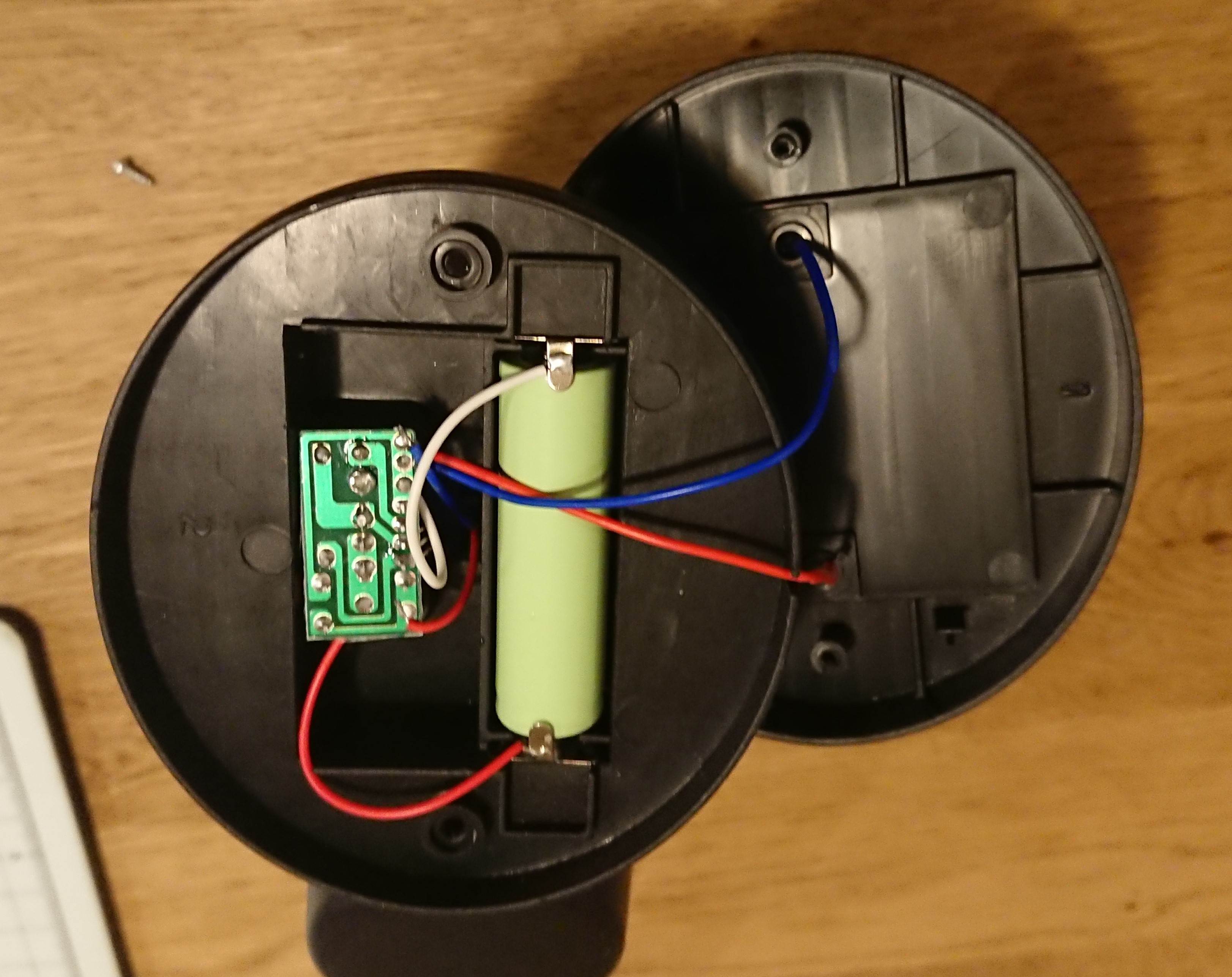
Remove the two screws on the back of the solar panel and open the housing to access the circuit board and batteries for battery charge control and LED lighting control.
![]()
-
2Replace the battery
Ideally, the system should be operated using only the power generated by the solar panel, but since we do not have sufficient know-how in power saving, we will change to a rechargeable battery with a higher capacity.
The capacity of the included battery is 200 mAh, but we will replace it with a 2400 mAh battery.
![]()
Below is the standard battery and above is the battery used.
-
3Replacing the cables on the charge control board
The garden light uses an IC called YX8055 to charge the battery while the solar panel is generating power and to turn on the LEDs when the power generation stops.
![]()
Disconnect the power supply cable to the LED and relocate it to the main power line. Power is constantly supplied to the SPRESENSE through this cable.
The upper image is before the cable was replaced, and the lower image is after the cable was replaced.
-
4Disassemble the lighting section
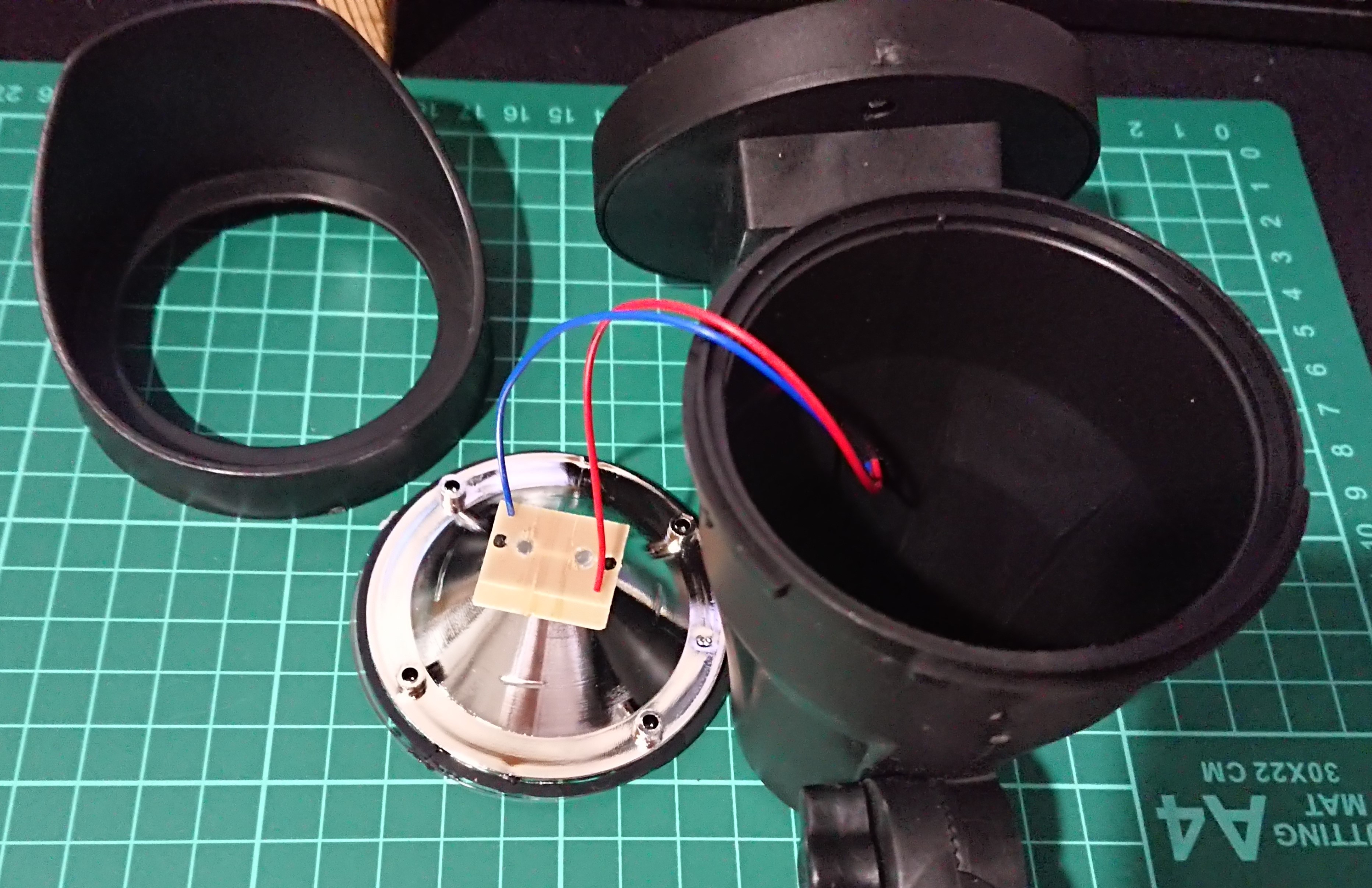
The lighting section can be dis
![]()
assembled by rotating the hood.
-
5Remove the LED board and disconnect the cable.
Remove the removed LED board from the reflector and also remove the power cable.
-
6Painting the cover plate
Paint the resin cover plate with red marker to make it flash red when an alert occurs. Apply from both sides for a clean coating.
![]()
-
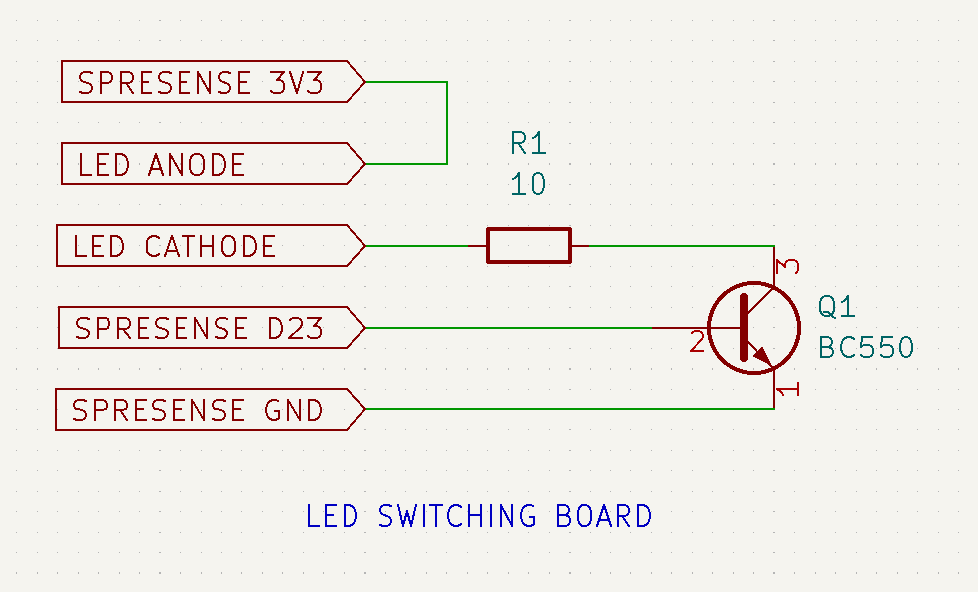
7Making LED Switching board
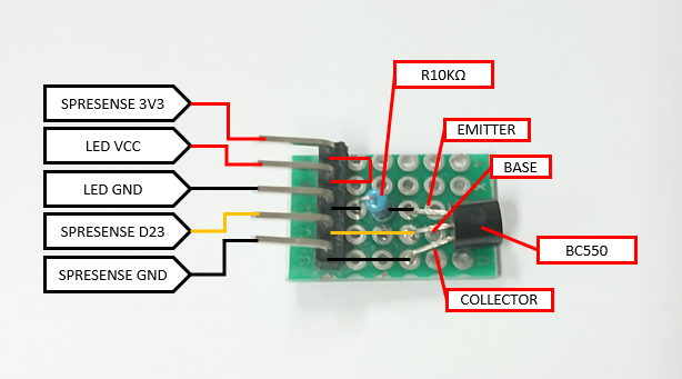
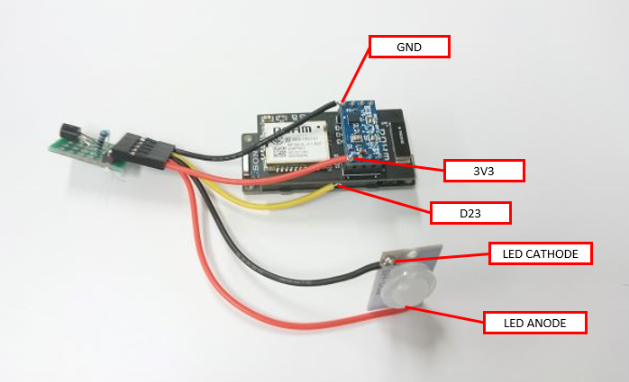
To drive the LEDs, switching is done using NPN transistors. The circuit is configured as shown in the photo and connected to the LED board of the garden light and the Spresense main board.
![]()
![]()
-
8Connect the boards
The Wi-SUN add-on board is mounted on the main board of the SPRESENSE, and the accelerometer board is mounted on top of it. Since there are no available pins, 3V3 and GND are soldered directly to the header pins on the accelerometer board, and D23 is soldered directly to the base of the pin socket on the Wi-SUN add-on board.
![]()
Please make and use a cable with a QI connector female 5-pin connector on one side for connecting each board.
-
9Confirmation of board operation
The program is written to the Spresense and the receiving RPi to check the operation. After startup, tilt the Spresense and when the tilt exceeds the threshold, the LED flashes.
The following message is received at the receiving Raspberry Pi.
```
Python 3.9.2 (/usr/bin/python3)
>> %Run wisun_rcv3.py
/dev/ttyUSB02022-08-25 17:26:05.813143
ID= LSA0001
STATUS= launch
GNSS= 1111/22222022-08-25 17:26:23.151292
ID= LSA0001
STATUS= in range
DEGREE= 0.7682022-08-25 17:26:40.251368
ID= LSA0001
STATUS= alert
DEGREE= 47.673```
17:26:05 the system is launched (status = launch), GNSS is dummy data as it is not yet implemented.
17:26:23 Returned from deepsleep and measured the amount of tilt change, which was 0.768°, so within acceptable range (status = in range).
17:26:40 Alert issued because the amount of change in tilt exceeds the threshold value of 5° (status=alert)
-
10Install DC-DC upconverter
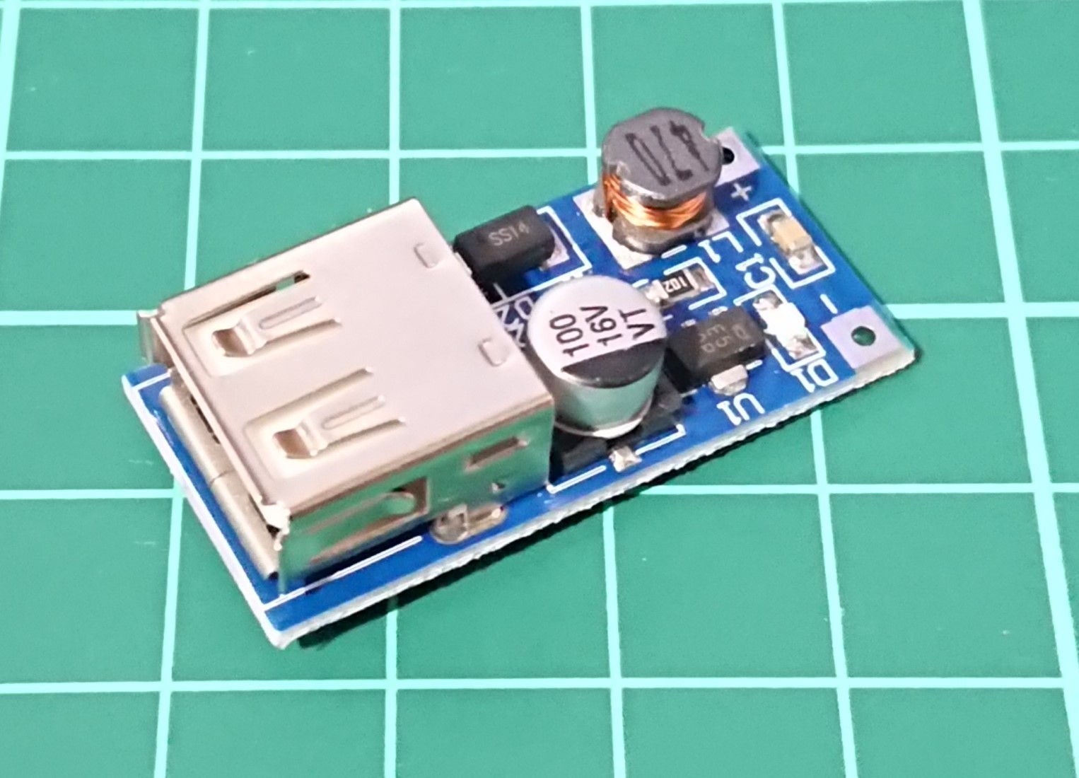
The power supply line used to light the LEDs in the garden light is used to drive the Spresense main unit. Since the supply voltage is low, it is boosted to 5 V with the voltage booster module HY-106.
Solder the red and blue cables leading to the garden light control board to the positive and negative terminals of the HY-106.
The power supply boosted to 5V by HY-106 is available through the USB TYPE A connector.
DIY Landslide Warning System
Japan is a mountainous country and many landslides occur during the rainy season. This device detects and reports signs of landslides.
 AIRPOCKET





Discussions
Become a Hackaday.io Member
Create an account to leave a comment. Already have an account? Log In.