 Open Green Energy
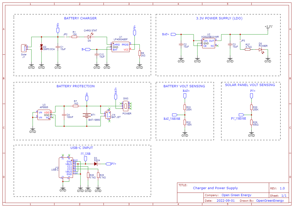
If you are planning to install the weather station at a remote location like your farmhouse, you may not get access to the power grid to run the weather station. To run the station continuously, there must be a continuous power supply otherwise the system will not work. The best way to provide continuous power to the circuit is by using a battery. But in the case of the battery, after some days of run, its juice will run out, and it is a really difficult job to go there and charge it. So a solar charging circuit was proposed to use free energy from the sun to charge the battery and power the PCB board.
Li-Ion/LiPo Battery Charger:
The battery is charged from a Solar panel through an LP4060 charging IC. The charger circuit charges the battery by taking power generated from the solar panel. It is based on a lithium-ion battery charger IC LP4060. It is a complete constant-current/constant-voltage linear charger for a single-cell lithium-ion battery. It uses only a few external components like resistor ( R6 ) and capacitors ( C1 & C12 ). The circuit is based on the application circuit given in the datasheet.
The CHG_STAT LED ( D1 ) is used to indicate the battery charging status, it will turn off when the charging is finished. You can enable this LED by shorting the jumper JP2.
Battery Protection:
The Battery Protection Circuit provides various protections to the Li-Ion battery. The circuit is based on IC - AP6685 which contains internal power MOSFET, high-accuracy voltage detection circuits, and delay circuits. The IC has the following protections inbuilt:
1. Reverse polarity protection
2. Over Charge Protection
3. Over-Discharge Protection
4. Load short circuit protection
The circuit diagram for both the charger and protection circuits is derived from their datasheets. The datasheets are attached below.
1. LP4060
2. AP6685
USB-C Input:
USB-C port is used for faster charging of Lithium Ion Battery. The 18650 battery outputs 4.2V when fully charged. The resistors R25 and R26 are used as pull-down resistors.
3.3V Power Supply:
The operating voltage of the ESP32 and LoRa module is 3.3V whereas the fully charged battery voltage is 4.2V. So we have to step down the battery voltage from 4.2V to 3.3V, which can easily be done by a linear voltage regulator but unfortunately, it is not at all recommended for this project. Because all the linear regulators require an input voltage at least some minimum amount higher than the desired output voltage. That minimum amount is called the dropout voltage. Due to this reason when battery voltage drops to around 3.7V, the linear voltage regulator will not be able to maintain the required voltage ( 3.3V ).
The solution to the above problem is to use a low-dropout or LDO regulator. A low-dropout or LDO regulator is a DC linear regulator which can regulate the output voltage even when the supply voltage is very close to the output voltage. Here we will use an XC6220B331MR LDO for efficiently powering the Circuit.
The capacitors ( C2 and C3 ) are connected to the input and output of the LDO to smooth the voltage peaks.
Solar Panel and Battery Voltage Sensing:
The max allowed voltage input to the ADC pin of the ESP32 is around 3.2~3.3V but a fully charged 18650 battery and solar panel voltage are in the range of 4 - 6V. So to measure these voltages we have to step down the voltages by using voltage divider networks.
The battery voltage is sensed by the voltage divider consisting of R2 and R3. Similarly, the solar panel voltage is sensed by the voltage divider consisting of R4 and R5
The voltage divider formula is as follows:
Vbat_sense = (Vbat*R3)/(R2+R3)
Vsol_sense = (Vsol*R5)/(R4+R5)
Discussions
Become a Hackaday.io Member
Create an account to leave a comment. Already have an account? Log In.