Open Green Energy
-
Published New Software
11/10/2022 at 08:49 • 1 commentPublished a new version of code with implementing MQTT. The software is developed by my friend Jame Hughes.
You may find the details in the following link.
https://jameshughes.atlassian.net/wiki/spaces/WSVL/pages/1963360257/Software+Notes
Released a stable version of the software for both the Base Station and Receiver Node. You can find it on Jame's GitHub Page.
1. Download the Code for Transmitter ( Base Station ) here
2. Download the Code for the Receiver Node here.
Your feedback is useful for us, please suggest us for improvement. -
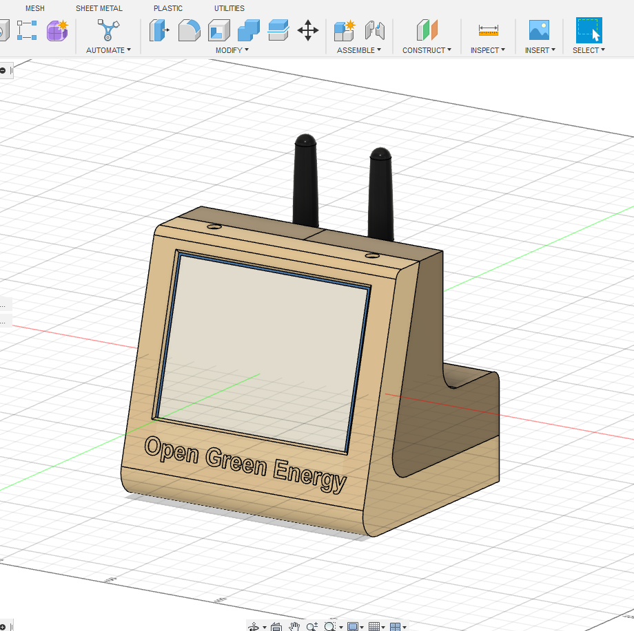
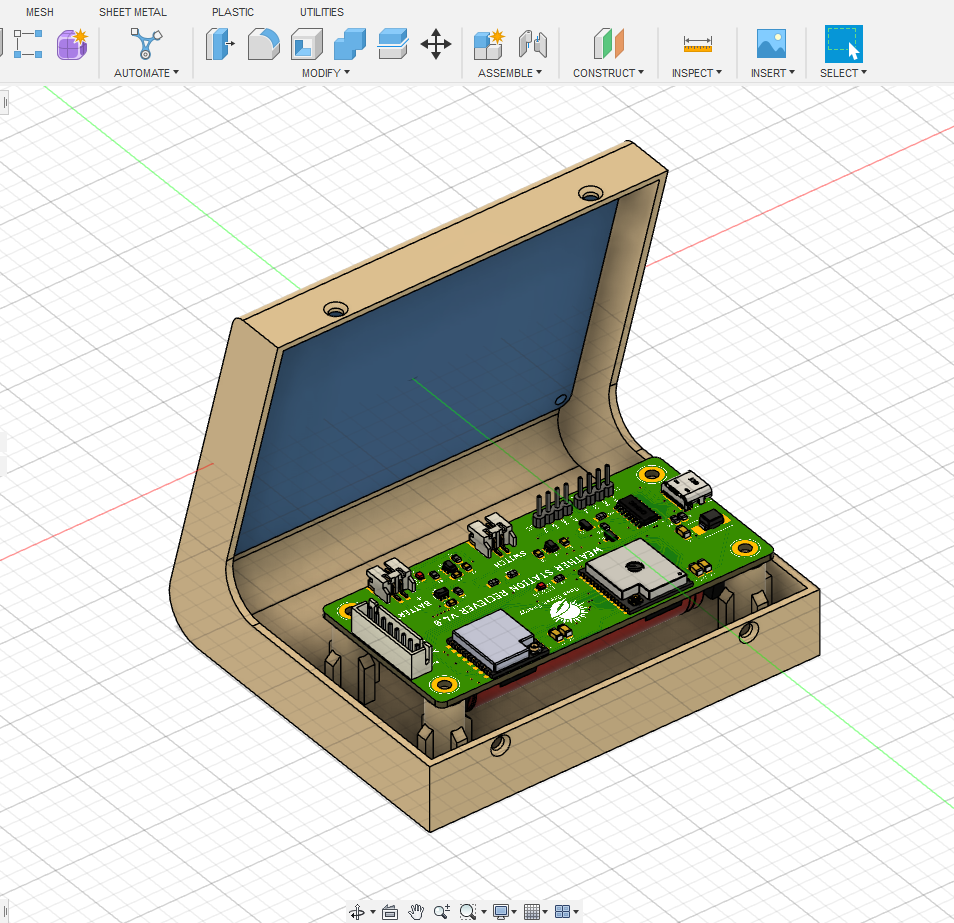
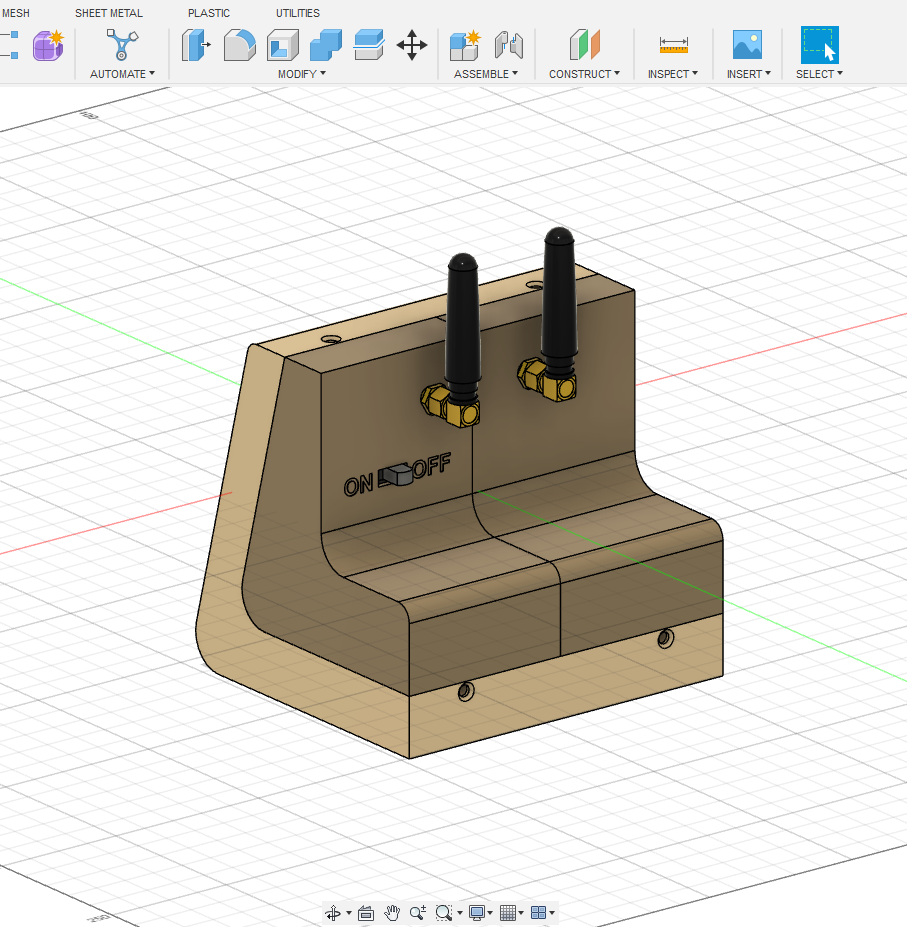
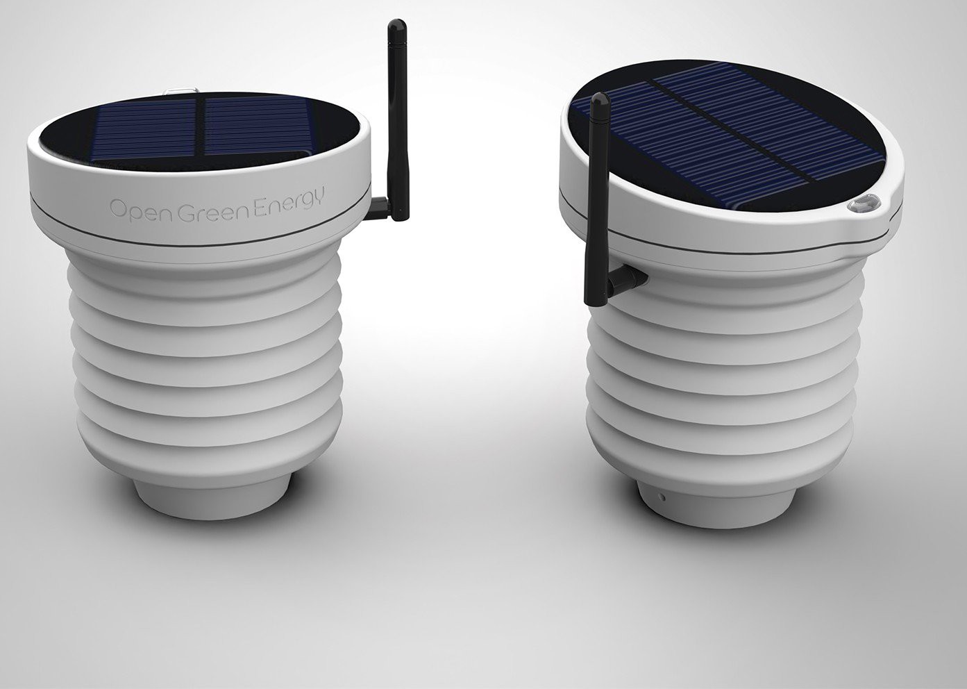
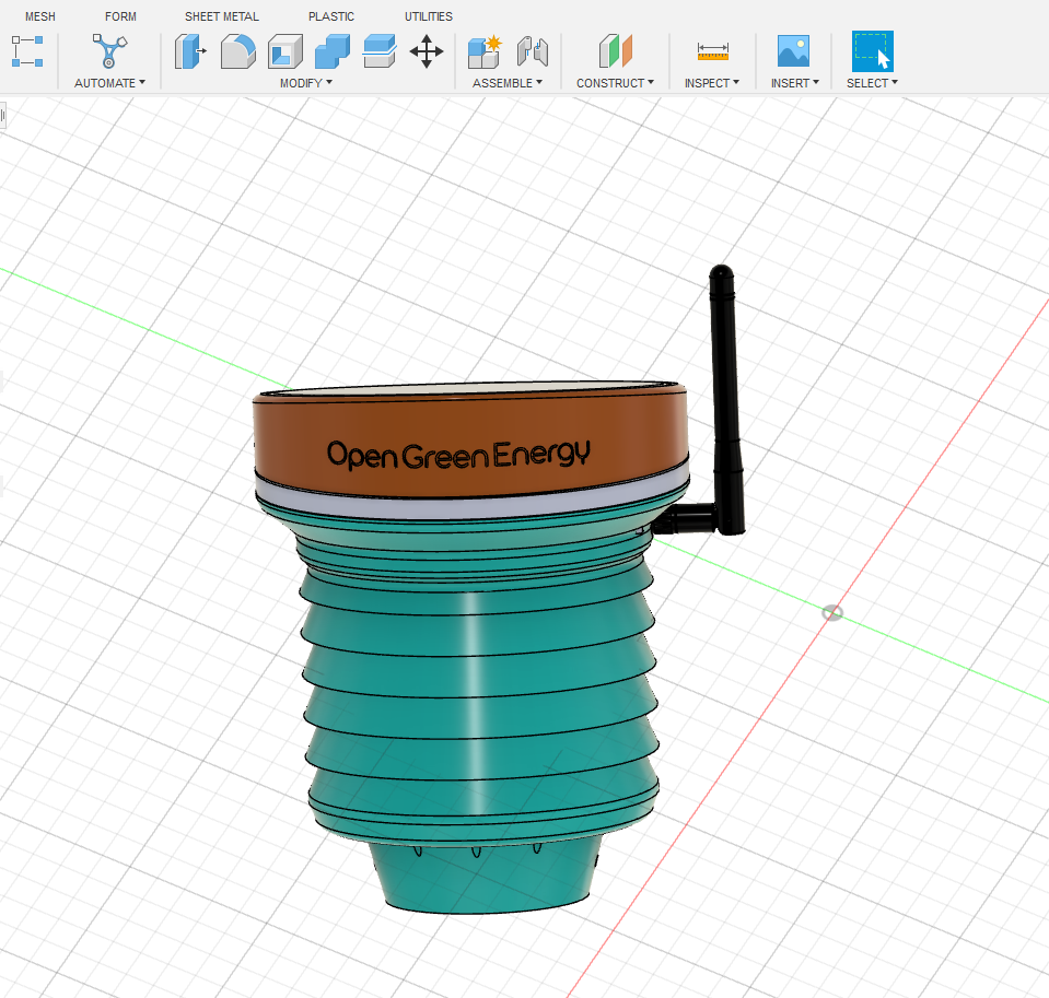
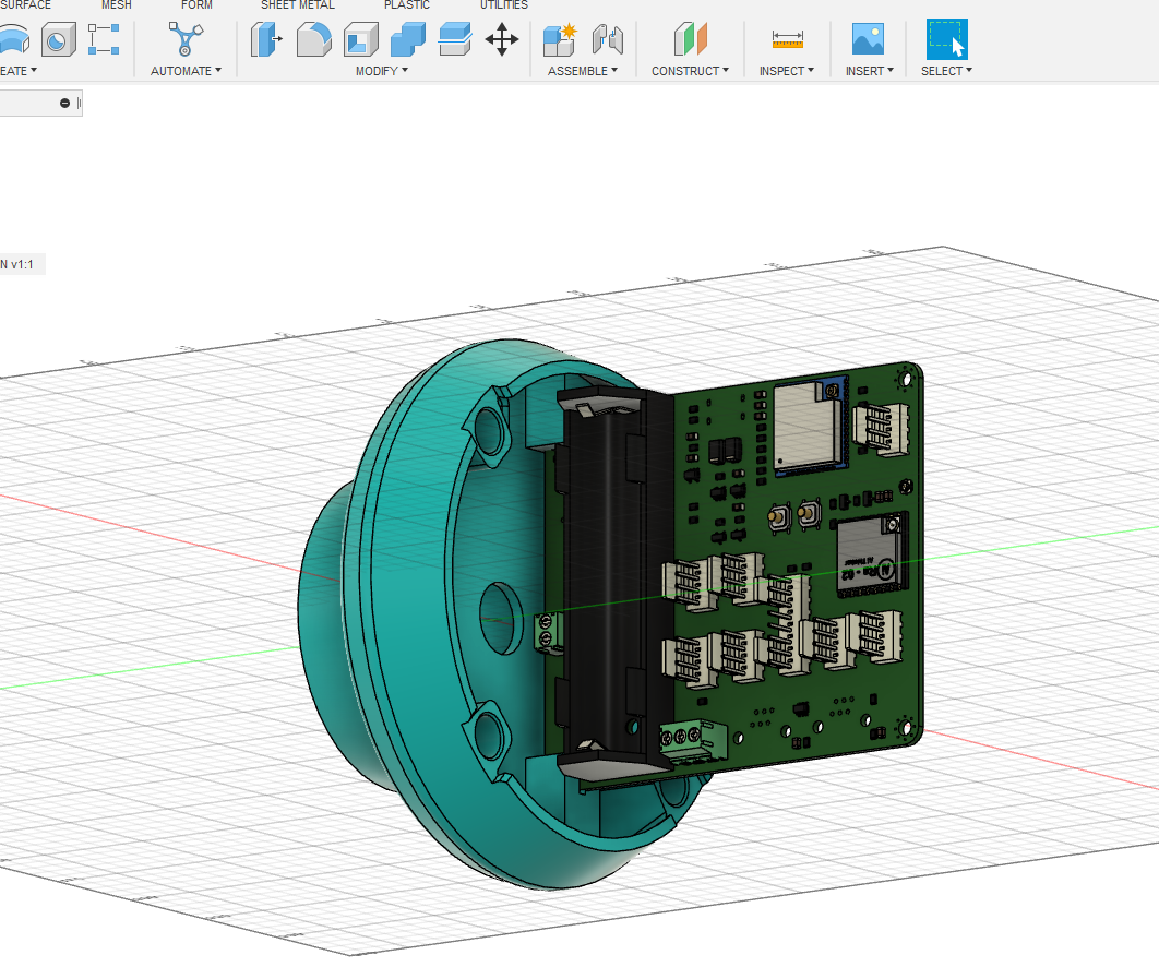
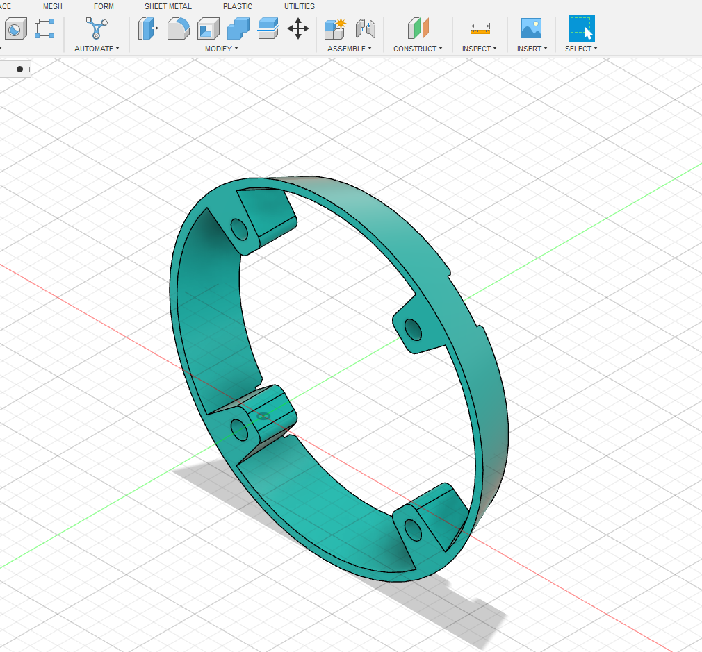
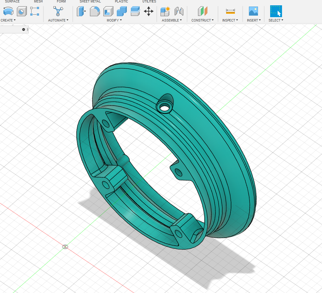
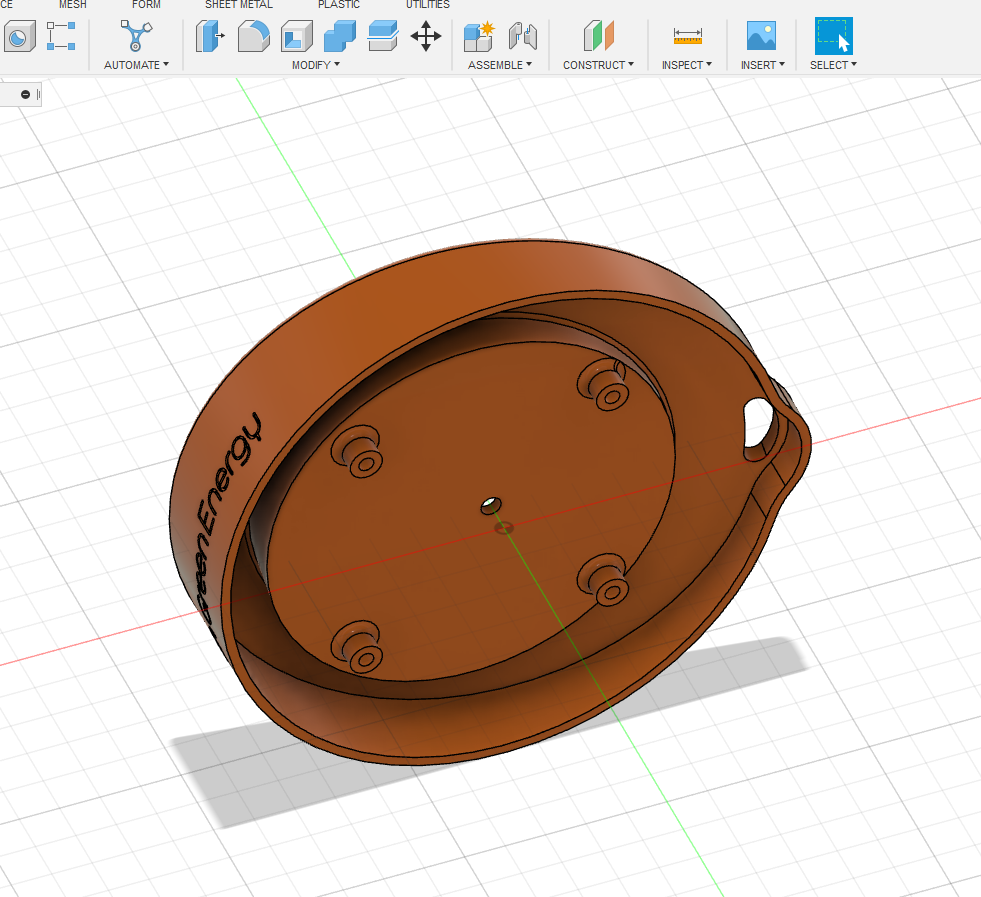
Designed an 3D printed Enclosure for Receiver
09/27/2022 at 17:58 • 0 commentsI have designed an enclosure in Fusion360 for the weather station receiver node. It includes a 4.2" e-paper display and my customized receiver PCB board. I have also included antennas for both the ESP32 and LoRa modules.
The pictures of my designs are attached below:
![]()
![]()
![]()
-
Receiver PCB Board Assembled
09/27/2022 at 17:41 • 1 commentToday I assembled the PCB board, but the USB port was not soldered due to the unavailability of stock. As the USB port is not soldered, not able to upload the program now, Place the order for the USB-C port, it will be delivered by this weekend, I will update the results then.
Placed the components using Solder Paste:
![]()
Assembled PCB:
![]()
-
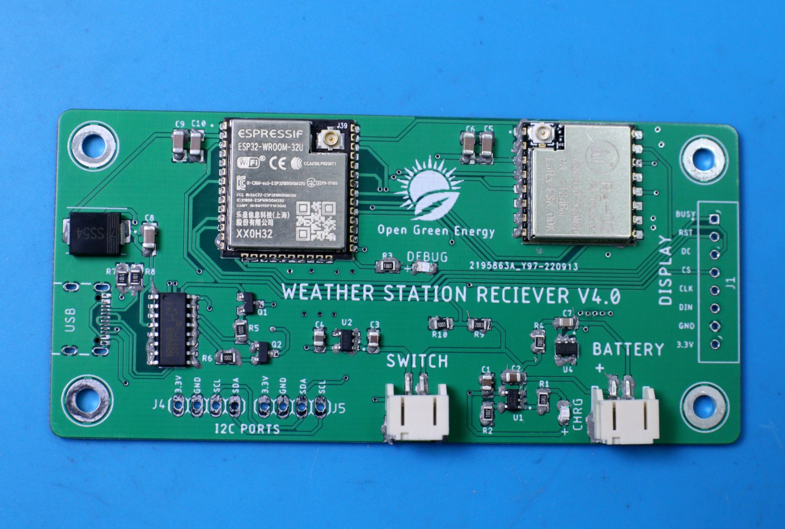
Receiver Node PCB Arrived
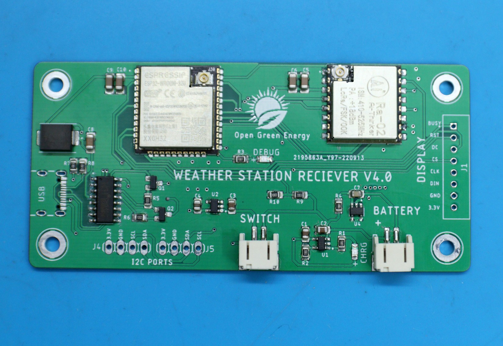
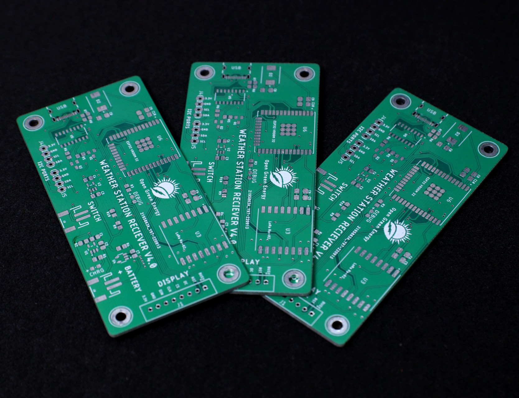
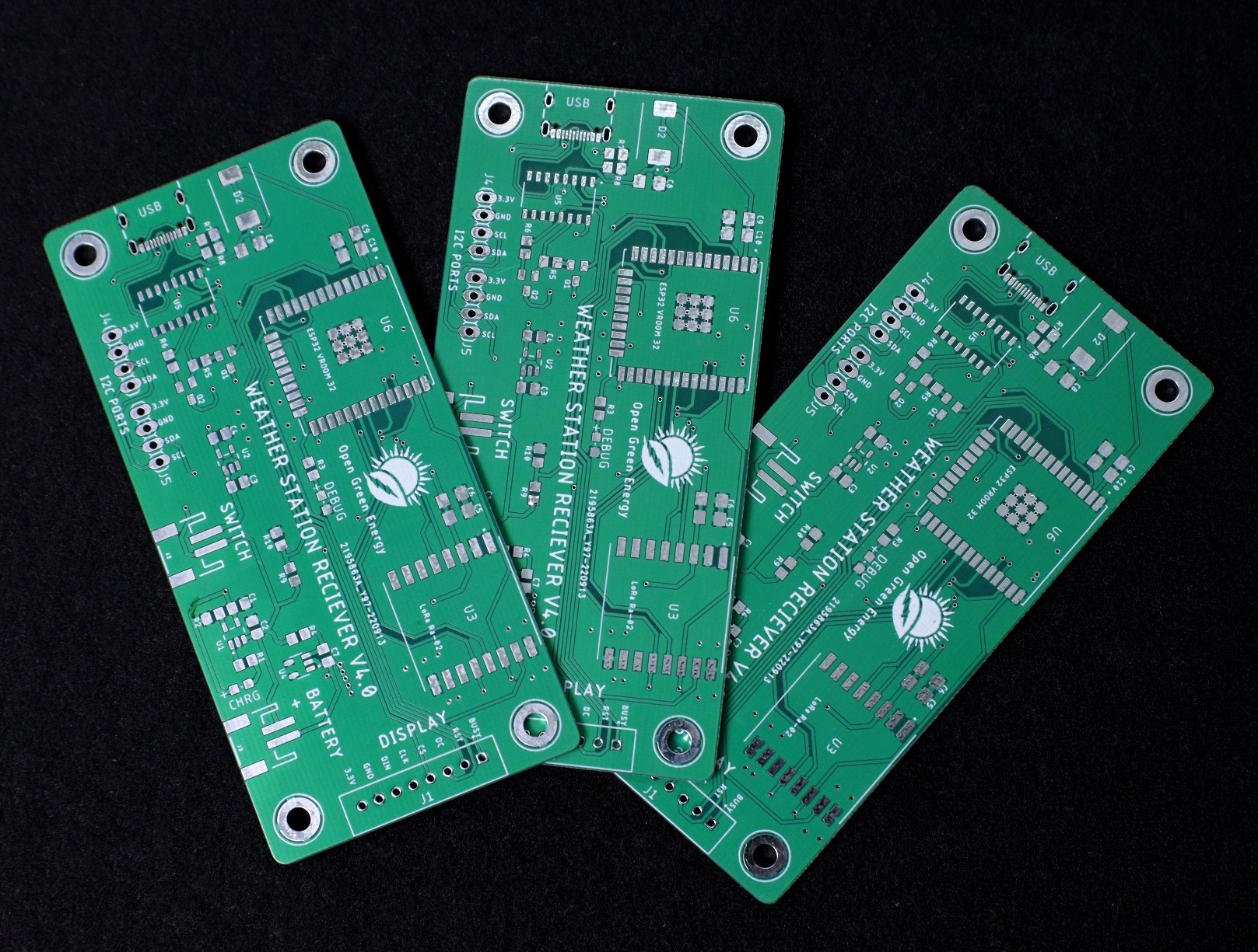
09/26/2022 at 19:02 • 1 commentToday I received the PCB for the receiver board from PCBWay. The PCB quality is extremely good. I am excited to assemble it and see the results. Stay tuned, I will update the results soon.
The pictures of the new PCBs are attached below.
![]()
![]()
-
Ultra Low Power Consumption
09/22/2022 at 14:48 • 0 commentsThe heart of our Weather Station is an ESP32 SOC, a power-hungry chip. When the project is powered by a plug-in wall, you tend not to care too much about power consumption. But if you are going to power your project with batteries, every mA counts.
Our objective is to run the device by using a 18650 Li-Ion battery. To run the ESP32 by using a battery, we have to lower the power consumption. The power consumption can be reduced in the following ways:
1. Software Optimization
2. Hardware Optimization
Software Optimization:
Using Deep Sleep Mode which is the most power-efficient option for the ESP chip. It allows to put the ESP32 into hibernation and saves the battery. You can wake up the ESP at regular intervals to make measurements and publish them.
Hardware Optimization:
The power-consuming components in the PCB are LEDs, ESP32, LoRa, and Sensors. The ESP32 power consumption can be minimized by software optimization. However, we can reduce the power consumption of all other components by optimizing hardware design.
I have considered the following in my hardware design to reduce the power consumption
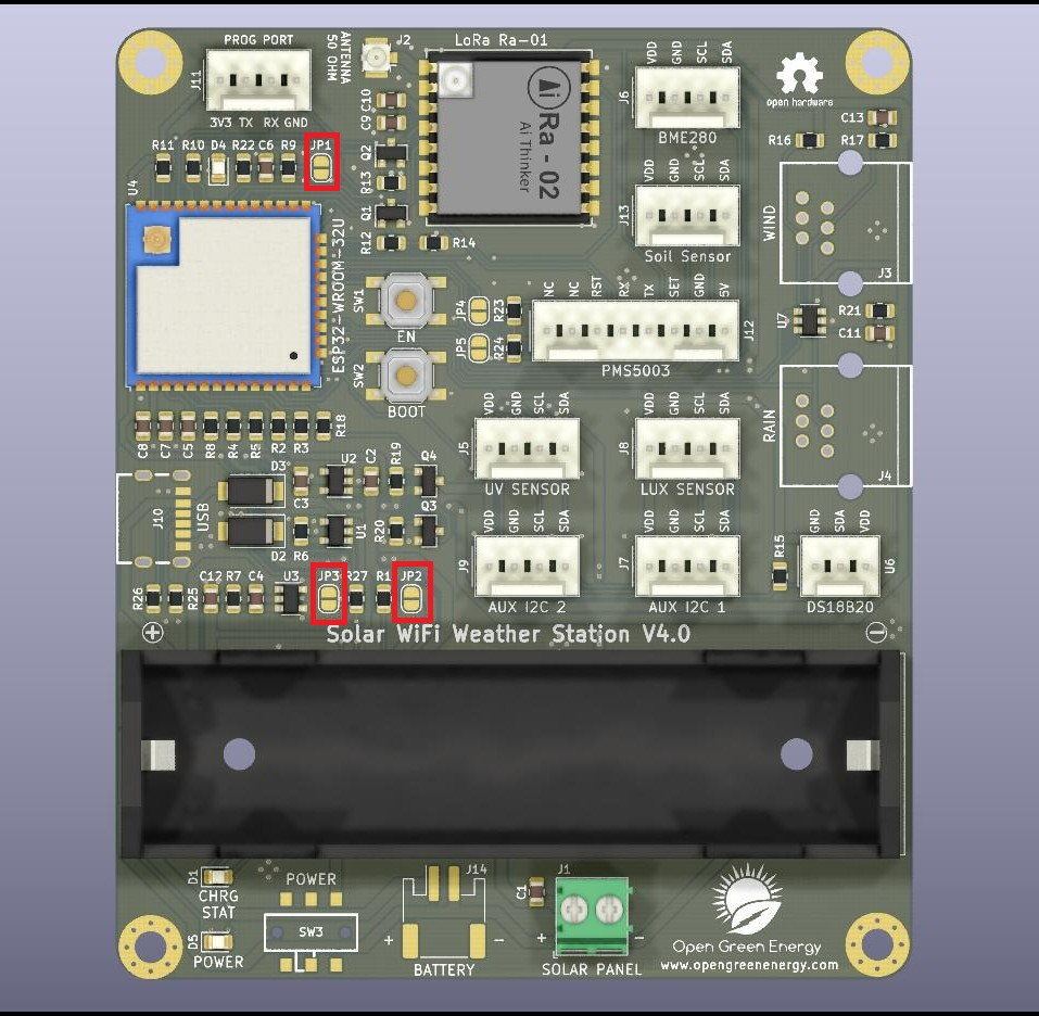
A. LED jumpers:
![]()
You can enable/disable all the 3 LEDs ( DEBUG, CHRG, and POWER ) used in the PCB board by using the jumpers JP1, JP2 and JP3. The default state is in disable condition, but if you need them, bridge the Jumpers by applying solder.
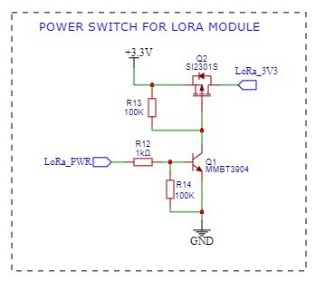
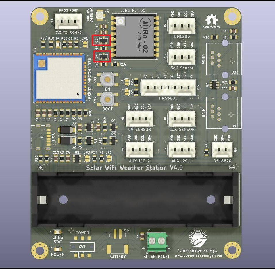
B. Power Switch for LoRa:
![]()
![]()
I have added a power switch circuit by using a MOSFET ( Q2) and transistor ( Q1 ) for complete shut down of the LoRa module during the sleep mode. The ESP32 GPIO pin 16 is used to control this power switch.
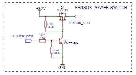
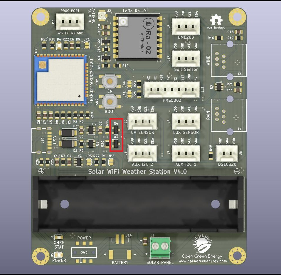
C. Power Switch for Sensors:
![]()
![]()
I have added a power switch circuit by using a MOSFET ( Q3) and transistor ( Q4 ) for the complete shutdown of all the sensors during sleep mode ( when no sensor data is to be sent). The ESP32 GPIO pin 26 is used to control this power switch.
-
3D printed the Enclosure
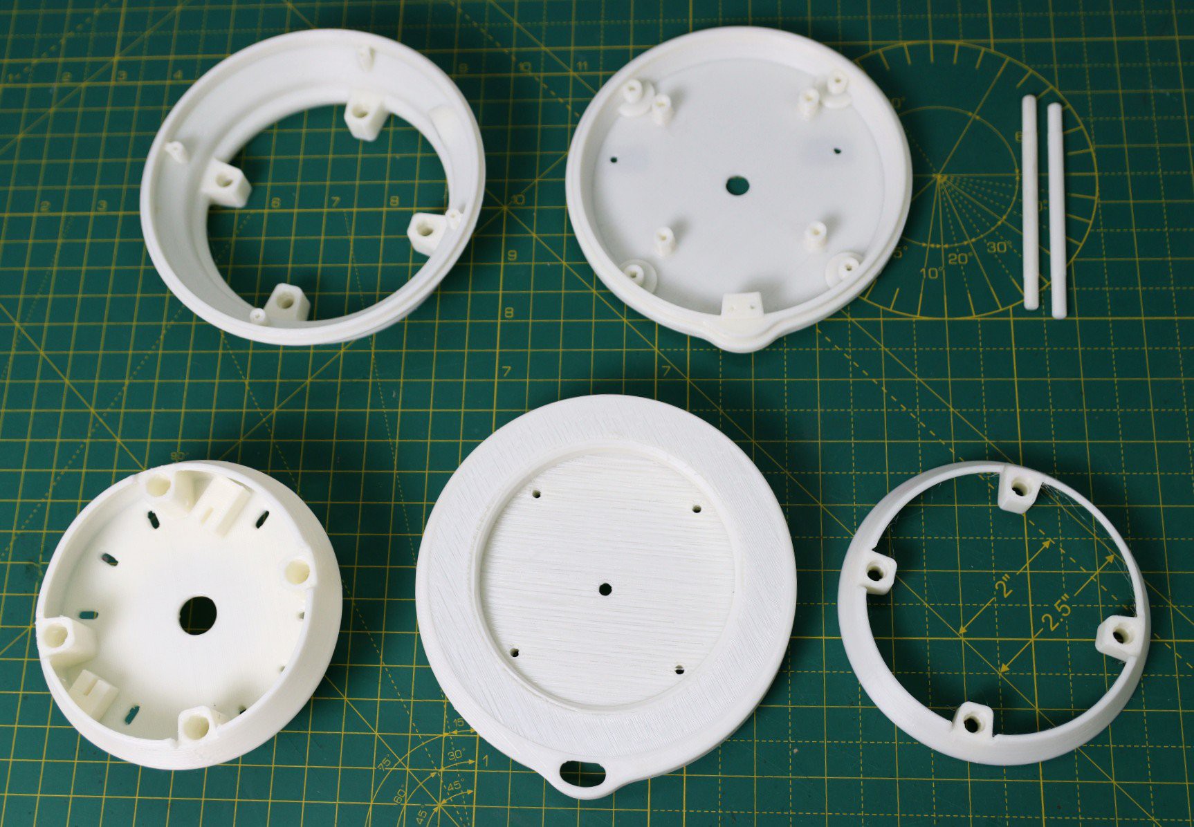
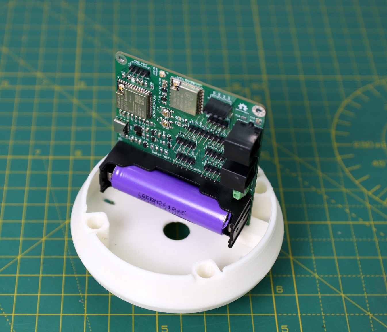
09/21/2022 at 06:55 • 0 commentsI used my Creality 3D printer and 1.75 mm white PLA filament to print the parts. I will recommend using ABS or PTEG filament instead of using PLA. I have used PLA just for the quick test as I don't have ABS or PTEG filament in my stock.
![]()
![]()
My print settings are:
Print Speed : 60 mm/s
Layer Height: 0.3mm
Fill Density: 25%
Extruder Temperature: 210 deg C
Bed Temp: 65 deg C
I have printed the files successfully but there are minor issues in the fitting of a few parts like M4 rods, and middle cover, and the top cover. I will adjust it soon.
![]()
![]()
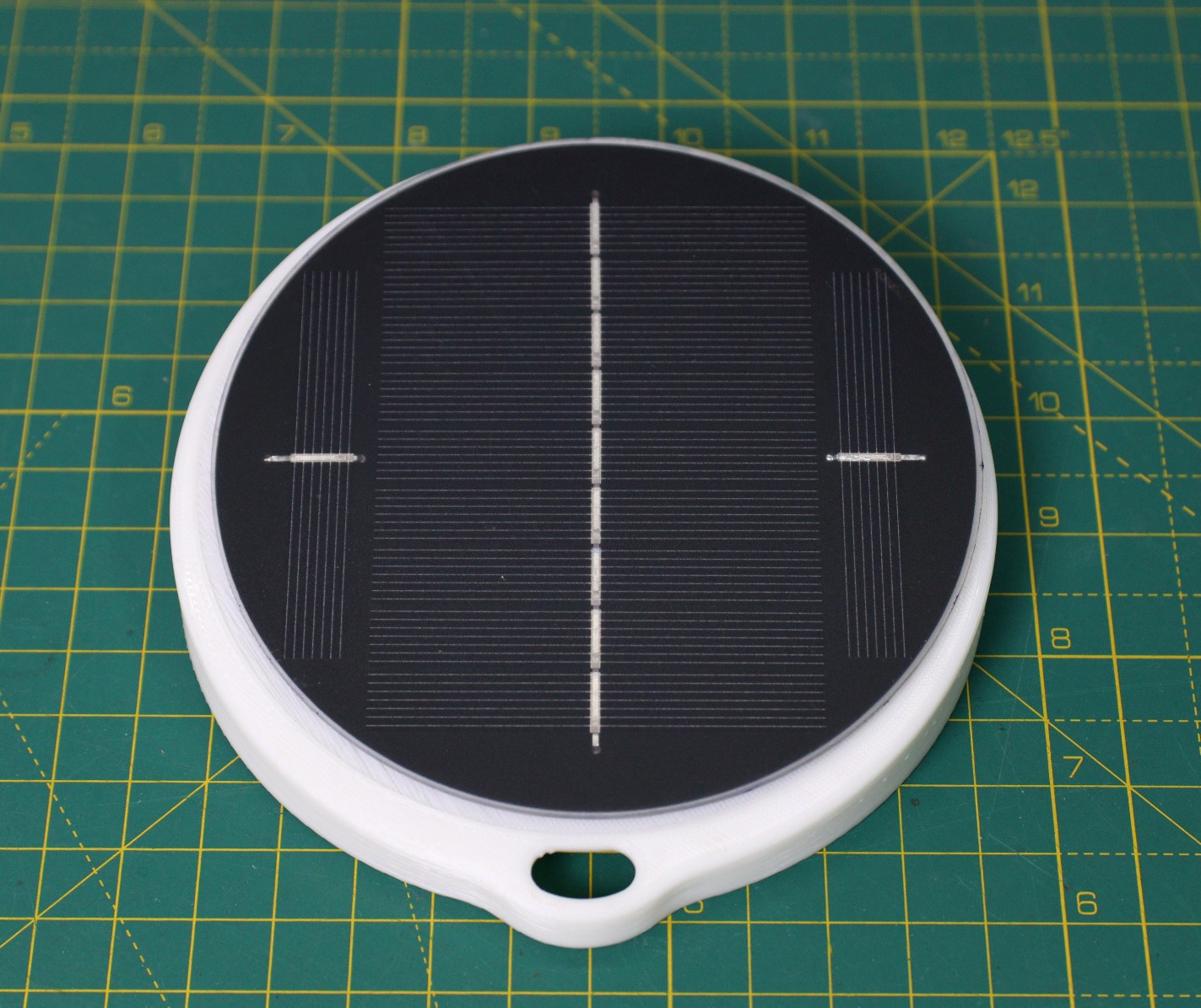
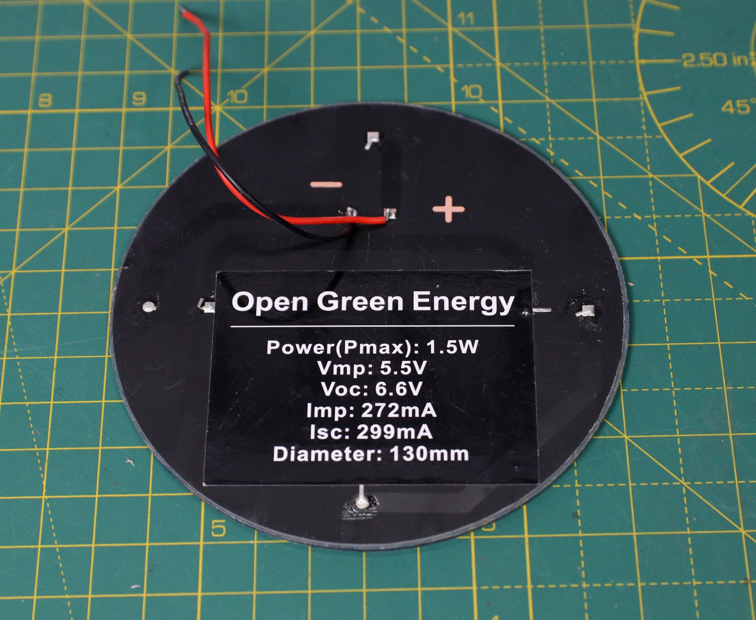
I have also checked the solar panel fitting, it works as expected.
-
Designed a 3D printed Stevenson Screen
09/20/2022 at 19:00 • 0 commentsThe ideal enclosure for keeping the weather sensors is the Stevenson Screen. A Stevenson screen is an enclosure to shield meteorological sensors against precipitation and direct heat radiation from outside sources, while still allowing air to circulate freely around them.
![]()
I have designed a 3D printed Stevenson screen to keep the weather sensors and PCB board. The enclosure has the following parts:
1. Base part
2. 4 x Middle Rings
3. Middle Cover ( Separate the Solar panel from the PCB chamber )
4. Top Cover ( above which a 130 mm circular solar panel will be mounted )
The whole idea is to stack all the above parts one above the other so that the inside chamber will be well-ventilated from the outside.
The above parts will be assembled by using 4x M4 rods, it can also be 3D printed.
Full Enclosure:
![]()
Base Part:
![]()
Middle Rings: ( Required 4 Numbers )
![]()
Middle Cover:
![]()
Top Cover:
![]()
-
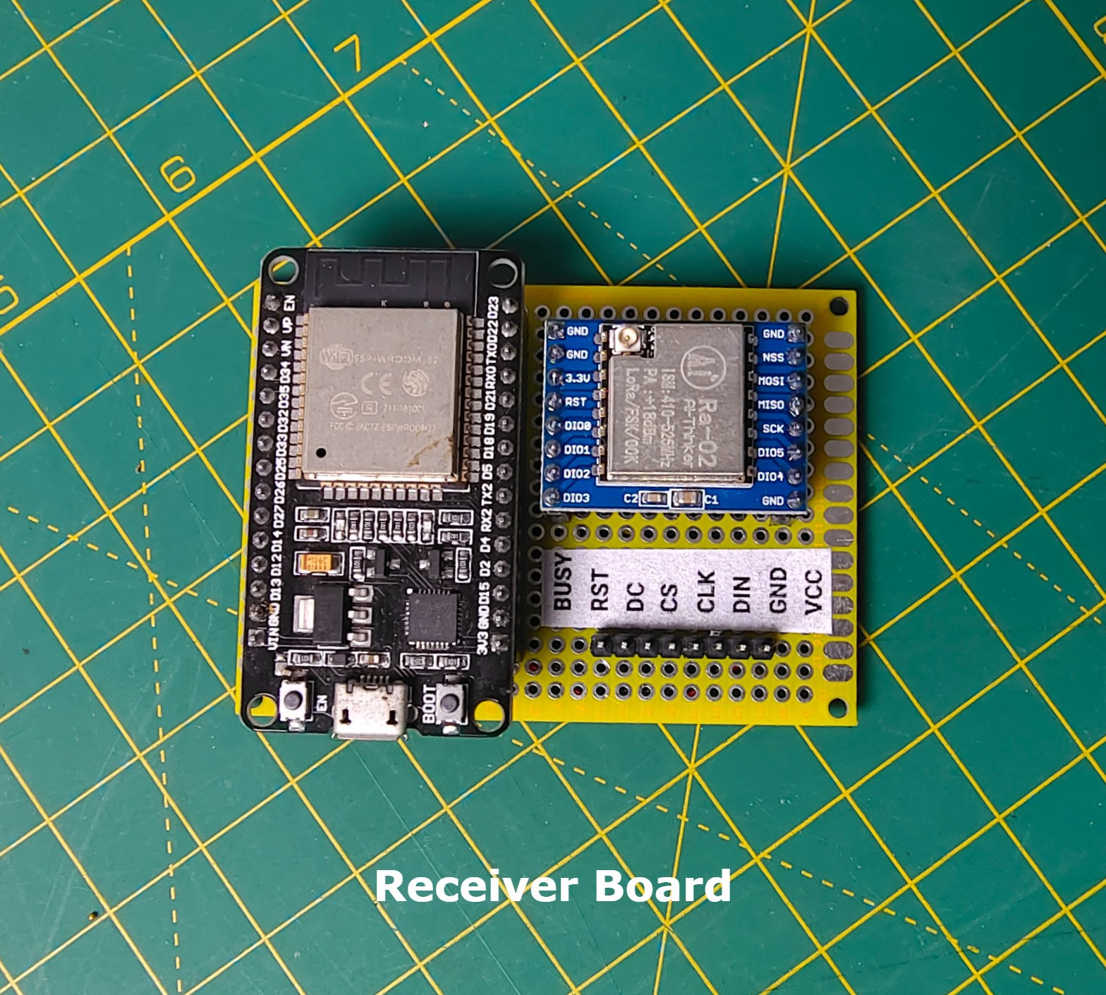
Prototype for Receiver Board
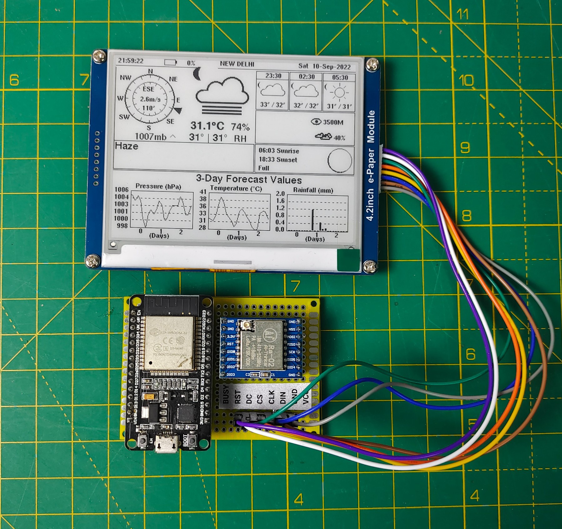
09/20/2022 at 06:56 • 1 commentI have made a prototype board to check the main feature of the above circuit on a perforated board. I tested the board with a BME280 sensor hook up to the Sender Board, and finally received the sensor data successfully.
Here are some pictures of my prototype test
![]()
![]()
Interfacing with 4.2" e-paper Display:
I have tested the prototype board with the same pin assignment as I have done in the above schematic diagram. My idea is to make a customized display with all the sensor data and some icons and graphs.
I found a beautiful code on GitHub with a similar thought, but the author uses weather data from Open Weather Map instead of actual sensor data. My plan is to modify the existing code to incorporate the sensor data and retain the weather icons and graphs.
I just uploaded the example code to my receiver board, and it works satisfactorily. No, my challenge is to tweak the existing code to achieve the desired goal.
![]()
-
Successfully Uploaded the Test Code to Transmitter Board
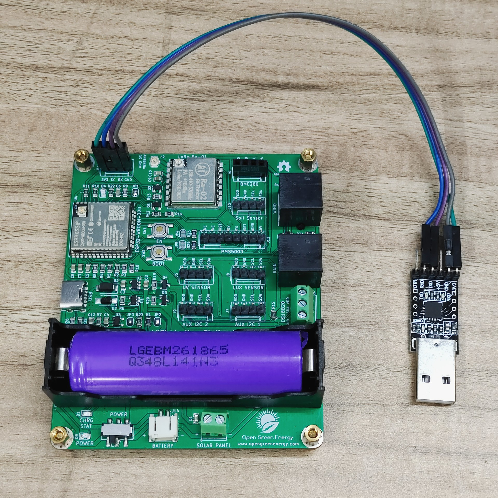
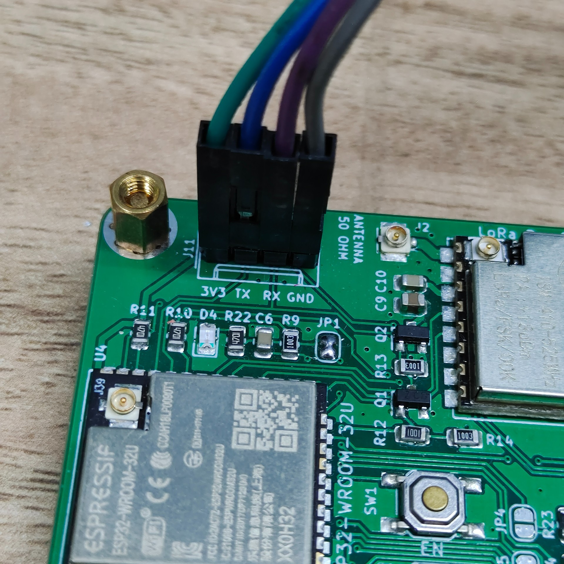
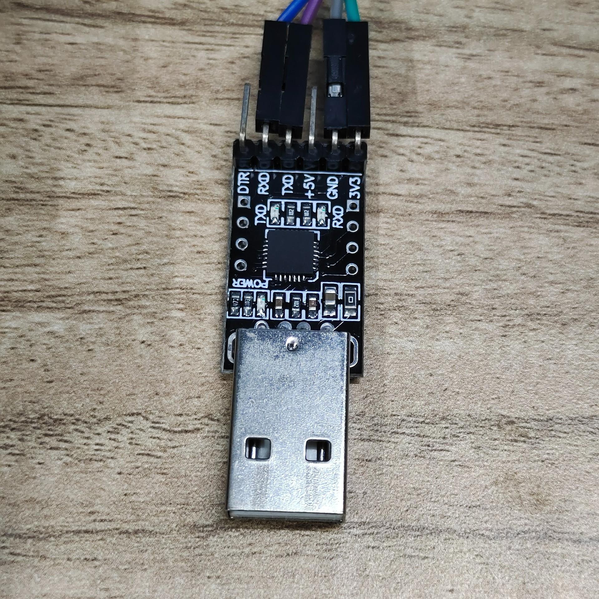
09/20/2022 at 06:46 • 0 commentsAfter assembling the transmitter PCB board, I connected my USB to the TTL UART programmer to the programming port. The connections are as follows:
Programmer -----> PCB
3V3 ----> 3V3
Tx----> Rx
Rx----> Tx
GND---> GND
![]()
![]()
![]()
After connecting the programmer to the PCB board, I successfully uploaded the test code. The board is working as expected but I have to press the EN switch to start the execution. This is required only once after uploading the code.
I have tested the following:
1. All the I2C ports are working
2. Wind and Rain Sensors Ports working
3. DS18B20 port is working
4. Battery charging through solar panel and USB port is working
5. LoRa module is working as expected but needs an external antenna
6. Battery and Solar Panel Voltage monitoring working
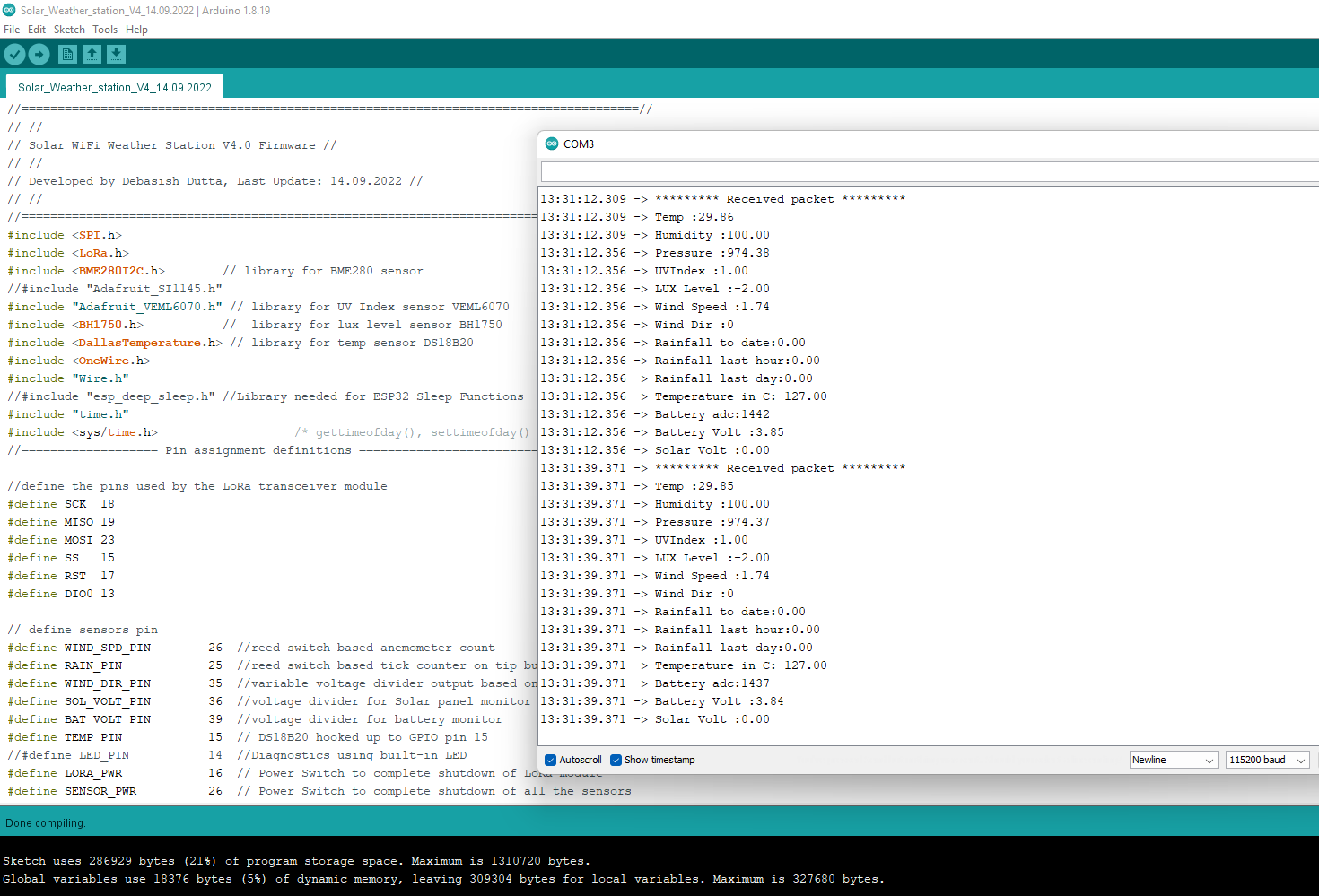
Test Code is attached below:
//======================================================================================// // // // Solar WiFi Weather Station V4.0 Firmware // // // // Developed by Debasish Dutta, Last Update: 14.09.2022 // // // //======================================================================================// #include <SPI.h> #include <LoRa.h> #include <BME280I2C.h> #include "Adafruit_SI1145.h" #include <BH1750.h> #include <DallasTemperature.h> #include <OneWire.h> #include "Wire.h" //#include "esp_deep_sleep.h" //Library needed for ESP32 Sleep Functions #include "time.h" #include <sys/time.h> /* gettimeofday(), settimeofday() */ //=================== Pin assignment definitions ========================================== //define the pins used by the LoRa transceiver module #define SCK 18 #define MISO 19 #define MOSI 23 #define SS 15 #define RST 17 #define DIO0 13 // define sensors pin #define WIND_SPD_PIN 26 //reed switch based anemometer count #define RAIN_PIN 25 //reed switch based tick counter on tip bucket #define WIND_DIR_PIN 35 //variable voltage divider output based on varying R network with reed switches #define SOL_VOLT_PIN 36 //voltage divider for Solar panel monitor #define BAT_VOLT_PIN 39 //voltage divider for battery monitor #define TEMP_PIN 15 // DS18B20 hooked up to GPIO pin 15 //#define LED_PIN 14 //Diagnostics using built-in LED #define LORA_PWR 16 // Power Switch to complete shutdown of LoRa module #define SENSOR_PWR 26 // Power Switch to complete shutdown of all the sensors #define batteryCalFactor 0.00263361 #define SolarCalFactor 0.00577798 //======================================================================================= //433E6 for Asia //866E6 for Europe //915E6 for North America #define BAND 433E6 //======================================================================================= BME280I2C bme; Adafruit_SI1145 uv = Adafruit_SI1145(); BH1750 lightMeter(0x23); OneWire oneWire(TEMP_PIN); DallasTemperature sensors(&oneWire); //=========================Declaring Variables and Constants ========================== // Variables used in reading temp,pressure and humidity (BME280) float temperature, humidity, pressure; // Variables used in reading UV Index (Si1145) float UVindex; // Variables used in reading Lux Level( BH1750 ) float lux; // Variables used in reading battery and solar panel voltage float batteryVolt; float SolarVolt; // Variables used in calculating the windspeed volatile unsigned long timeSinceLastTick = 0; volatile unsigned long lastTick = 0; float windSpeed; // Variables used in calculating the wind direction int vin; String windDir = ""; // Variables used for sending LoRa message String LoRaMessage; // Variables and constants used in tracking rainfall #define S_IN_DAY 86400 #define S_IN_HR 3600 #define NO_RAIN_SAMPLES 500 RTC_DATA_ATTR volatile long rainTickList[NO_RAIN_SAMPLES]; RTC_DATA_ATTR volatile int rainTickIndex = 0; RTC_DATA_ATTR volatile int rainTicks = 0; RTC_DATA_ATTR int rainLastDay = 0; RTC_DATA_ATTR int rainLastHour = 0; RTC_DATA_ATTR int rainLastHourStart = 0; RTC_DATA_ATTR int rainLastDayStart = 0; long secsClock = 0; //=========================Deep Sleep Time ================================================ //const int UpdateInterval = 1 * 60 * 1000000; // e.g. 0.33 * 60 * 1000000; // Sleep time const int UpdateInterval = 0.2* 60 * 1000000; // e.g. 15 * 60 * 1000000; // // Example for a 15-Min update interval 15-mins x 60-secs * 10000 RTC_DATA_ATTR int bootCount = 0; time_t now() { struct timeval tv = { .tv_sec = 0, .tv_usec = 0 }; /* btw settimeofday() is helpfull here too*/ // uint64_t sec, us; uint32_t sec, us; gettimeofday(&tv, NULL); (sec) = tv.tv_sec; (us) = tv.tv_usec; return sec; } //========================= Setup Function ================================================ void setup() { pinMode( LORA_PWR, OUTPUT); pinMode( SENSOR_PWR, OUTPUT); digitalWrite( LORA_PWR, HIGH); digitalWrite( SENSOR_PWR, HIGH); Serial.begin(115200); delay(25); Serial.println("nWeather station powered on.n"); //Increment boot number and print it every reboot ++bootCount; Serial.println("Boot number: " + String(bootCount)); // Wind speed sensor setup. The windspeed is calculated according to the number // of ticks per second. Timestamps are captured in the interrupt, and then converted into mph. pinMode(WIND_SPD_PIN, INPUT); // Wind speed sensor attachInterrupt(digitalPinToInterrupt(WIND_SPD_PIN), windTick, FALLING); // Rain sesnor setup. Rainfall is tracked by ticks per second, and timestamps of // ticks are tracked so rainfall can be "aged" (i.e., rain per hour, per day, etc) pinMode(RAIN_PIN, INPUT); // Rain sensor attachInterrupt(digitalPinToInterrupt(RAIN_PIN), rainTick, FALLING); if (bootCount == 1) { Serial.println("First boot"); // Zero out the timestamp array. for (int i = 0; i < NO_RAIN_SAMPLES; i++) rainTickList[i] = 0; } Serial.print("Time: "); Serial.println(now()); //Print the wakeup reason for ESP32 and touchpad too esp_sleep_wakeup_cause_t wakeup_reason; wakeup_reason = esp_sleep_get_wakeup_cause(); switch(wakeup_reason) { case ESP_SLEEP_WAKEUP_EXT0 : Serial.println("Wakeup caused by external signal using RTC_IO"); rainTick(); //Serial.println("Going to sleep now..."); //delay(1000); //esp_deep_sleep_start(); break; case ESP_SLEEP_WAKEUP_EXT1 : Serial.println("Wakeup caused by external signal using RTC_CNTL"); break; case ESP_SLEEP_WAKEUP_TIMER : Serial.println("Wakeup caused by timer"); break; case ESP_SLEEP_WAKEUP_TOUCHPAD : Serial.println("Wakeup caused by touchpad"); break; case ESP_SLEEP_WAKEUP_ULP : Serial.println("Wakeup caused by ULP program"); break; default : Serial.printf("Wakeup was not caused by deep sleep: %d\n",wakeup_reason); break; } esp_sleep_enable_ext0_wakeup(GPIO_NUM_25,0); //1 = High, 0 = Low //========================================== Wire.begin(); sensors.begin(); // Wire.begin(22, 21); // for BH1750 bme.begin(); // 0x76 is the address of the BME280 module uv.begin(0x60); // 0x60 is the address of the GY1145 module // Get 10 readings: for (int i = 0; i < 10; i++) { Read_Sensors_Data(); // Read all the Sensors delay(500); } initLoRa(); // intialize LoRa send_LoRa_Data(); //printdata(); // Print all the sensors data on the serial monitor // ESP32 Deep SLeep Mode esp_sleep_enable_timer_wakeup(UpdateInterval); Serial.println("Going to sleep now..."); Serial.flush(); esp_deep_sleep_start(); } //============== Code Block for LoRa Module ======================================================== void initLoRa() { SPI.begin(SCK, MISO, MOSI, SS); //SPI LoRa pins LoRa.setPins(SS, RST, DIO0); //setup LoRa transceiver module if (!LoRa.begin(BAND)) { Serial.println("Starting LoRa failed!"); while (1); } Serial.println("LoRa Initializing OK!"); } //====================== Send LoRa Message to Receiver =============================================== void send_LoRa_Data() { LoRaMessage = String(temperature) + "," + String(humidity) + "," + String(pressure / 100) + "," + String(UVindex) + ","+ String(lux) + "," ; LoRaMessage += String(windSpeed*2.4) + "," + String(windDir) + "," + String(float(rainTicks)*0.28) + "," + String(float(rainLastHour)*0.28) + "," + String(float(rainLastDay)*0.28)+ "," ; LoRaMessage += String(sensors.getTempCByIndex(0))+ "," + String(batteryVolt)+ "," + String(SolarVolt) + "," ; //String((sensors.getTempCByIndex(0) * 9.0) / 5.0 + 32.0) //Send LoRa packet to receiver Serial.println("Sending packet"); LoRa.beginPacket(); LoRa.print(LoRaMessage); LoRa.endPacket(); } //====================== Print Data on Serial Monitor =============================================== void printdata(){ Serial.print("Air temperature [°C]: "); Serial.println(temperature); Serial.print("Humidity [%]: "); Serial.println(int(humidity)); Serial.print("Barometric pressure [hPa]: "); Serial.println(pressure / 100); Serial.print("UV: "); Serial.println(UVindex); //Serial.print("Light: "); Serial.print(lux); Serial.println(" lx"); Serial.print("Windspeed: "); Serial.print(windSpeed*2.4); Serial.println(" mph"); Serial.print("Wind dir: "); Serial.print(" "); Serial.println(windDir); Serial.print("Rainfall last hour: "); Serial.println(float(rainLastHour)*0.28, 3); Serial.print("Rainfall last day: "); Serial.println(float(rainLastDay)*0.28, 3); Serial.print("Rainfall to date: "); Serial.println(float(rainTicks)*0.28, 3); Serial.print("Battery Level: "); Serial.println(batteryVolt); Serial.print("Temperature in C: "); Serial.println(sensors.getTempCByIndex(0)); //print the temperature in Celsius //Serial.print("Temperature in F: "); Serial.println((sensors.getTempCByIndex(0) * 9.0) / 5.0 + 32.0); //print the temperature in Fahrenheit } //================================ Loop Function ============================================== void loop() { //Read_Sensors_Data(); // Read all the Sensors //printdata(); // Print all the sensors data on the serial monitor //Send_Data(); // Upload all the sensors data on the Internet ( Blynk App or Thingspeak ) //delay(5000); // ESP32 Deep SLeep Mode // esp_deep_sleep_enable_timer_wakeup(UpdateInterval); // Serial.println("Going to sleep now..."); // esp_deep_sleep_start(); } void print_wakeup_reason(){ esp_sleep_wakeup_cause_t wakeup_reason; wakeup_reason = esp_sleep_get_wakeup_cause(); switch(wakeup_reason) { case ESP_SLEEP_WAKEUP_EXT0 : Serial.println("Wakeup caused by external signal using RTC_IO"); break; case ESP_SLEEP_WAKEUP_EXT1 : Serial.println("Wakeup caused by external signal using RTC_CNTL"); break; case ESP_SLEEP_WAKEUP_TIMER : Serial.println("Wakeup caused by timer"); break; case ESP_SLEEP_WAKEUP_TOUCHPAD : Serial.println("Wakeup caused by touchpad"); break; case ESP_SLEEP_WAKEUP_ULP : Serial.println("Wakeup caused by ULP program"); break; default : Serial.printf("Wakeup was not caused by deep sleep: %d\n",wakeup_reason); break; } } //=================================================================================================== // Read Sensors Data ( BME280, Si1145,BH1750, Bat. Voltage, Wind Sensors, Rain Gauge ) //================================================================================================== void Read_Sensors_Data() { // Reading BME280 sensor bme.read(pressure, temperature, humidity, BME280::TempUnit_Celsius, BME280::PresUnit_Pa); //*************************************************************************** // Reading DS18B20 sensor sensors.requestTemperatures(); //*************************************************************************** // Reading GY1145 UV sensor UVindex = uv.readUV(); // the index is multiplied by 100 so to get the // integer index, divide by 100! UVindex /= 100.0; //********************************************************************************** // Reading BH1750 sensor lux = lightMeter.readLightLevel(); //********************************************************************************** // Reading Battery and Solar Panel Voltage int adc1 = analogRead(BAT_VOLT_PIN); int adc2 = analogRead(SOL_VOLT_PIN); Serial.print("ADC1 Value:"); Serial.println(adc1); Serial.print("ADC2 Value:"); Serial.println(adc2); batteryVolt = adc1 * batteryCalFactor; // batteryCalFactor = Measured Battery Voltage / ADC Value or val SolarVolt = adc2 * SolarCalFactor; //********************************************************************************** // Read Weather Meters Datas ( Wind Speed, Rain Fall and Wind Direction ) static unsigned long outLoopTimer = 0; static unsigned long wundergroundUpdateTimer = 0; static unsigned long clockTimer = 0; static unsigned long tempMSClock = 0; // Create a seconds clock based on the millis() count. We use this // to track rainfall by the second. We've done this because the millis() // count overflows eventually, in a way that makes tracking time stamps // very difficult. //tempMSClock += millis() - clockTimer; //clockTimer = millis(); //while (tempMSClock >= 1000) //{ //secsClock++; //tempMSClock -= 1000; //} // This is a once-per-second timer that calculates and prints off various // values from the sensors attached to the system. //if (millis() - outLoopTimer >= 2000) //{ //outLoopTimer = millis(); // Windspeed calculation, in mph. timeSinceLastTick gets updated by an // interrupt when ticks come in from the wind speed sensor. if (timeSinceLastTick != 0) { windSpeed = 1000.0/timeSinceLastTick; Serial.print("wind: "); Serial.println(windSpeed); } // Calculate the wind direction and display it as a string. windDirCalc(); rainLastHour = 0; rainLastDay = 0; secsClock = now(); // If there are any captured rain sensor ticks... if (rainTicks > 0) { // Start at the end of the list. rainTickIndex will always be one greater // than the number of captured samples. int i = rainTickIndex-1; // Iterate over the list and count up the number of samples that have been // captured with time stamps in the last hour. while ((rainTickList[i] >= secsClock - S_IN_HR) && rainTickList[i] != 0) { i--; if (i < 0) i = NO_RAIN_SAMPLES-1; rainLastHour++; } // Repeat the process, this time over days. i = rainTickIndex-1; while ((rainTickList[i] >= secsClock - S_IN_DAY) && rainTickList[i] != 0) { i--; if (i < 0) i = NO_RAIN_SAMPLES-1; rainLastDay++; } rainLastDayStart = i; } } // Keep track of when the last tick came in on the wind sensor. void windTick(void) { timeSinceLastTick = millis() - lastTick; lastTick = millis(); } // Capture timestamp of when the rain sensor got tripped. void rainTick(void) { rainTickList[rainTickIndex++] = now(); if (rainTickIndex == NO_RAIN_SAMPLES) rainTickIndex = 0; rainTicks++; Serial.println("raintick"); } // reading wind direction void windDirCalc() { vin = analogRead(WIND_DIR_PIN); if (vin < 150) windDir="202.5"; else if (vin < 300) windDir = "180"; else if (vin < 400) windDir = "247.5"; else if (vin < 600) windDir = "225"; else if (vin < 900) windDir = "292.5"; else if (vin < 1100) windDir = "270"; else if (vin < 1500) windDir = "112.5"; else if (vin < 1700) windDir = "135"; else if (vin < 2250) windDir = "337.5"; else if (vin < 2350) windDir = "315"; else if (vin < 2700) windDir = "67.5"; else if (vin < 3000) windDir = "90"; else if (vin < 3200) windDir = "22.5"; else if (vin < 3400) windDir = "45"; else if (vin < 4000) windDir = "0"; else windDir = "0"; } //=============================End of the Program ================================= -
PCB for Transmitter Board
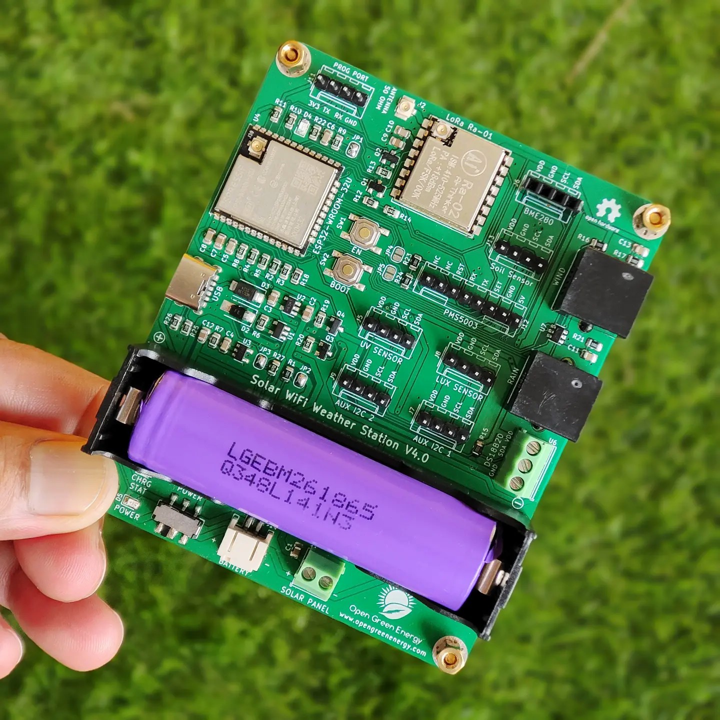
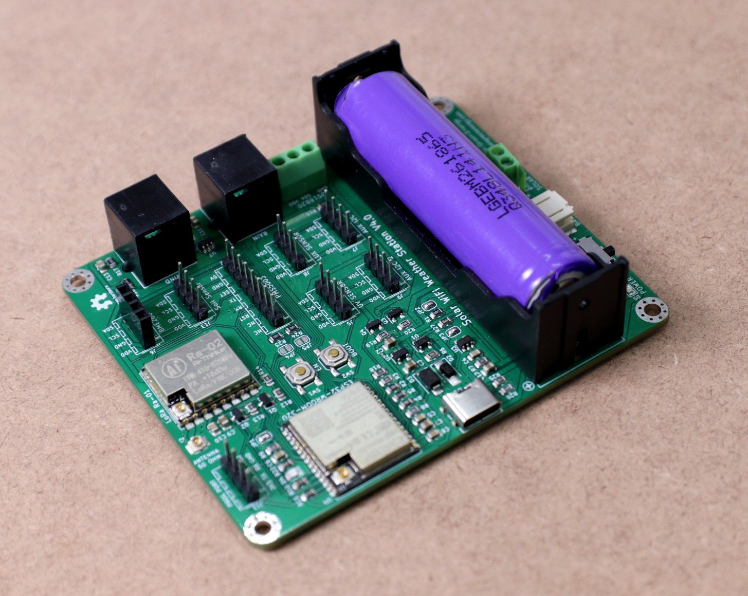
09/20/2022 at 06:10 • 0 commentsI have received the PCB from my transmitter board from PCBWay. Then I soldered the components using my own hot plate. The final look is really awesome, attaching a few pictures for the same.
![]()
![]()
The main features of the PCB are
1. 2 Battery Options: Either 18650 battery directly into the slot or LiPo battery through the battery JST connector
2. Solar charging port: " SOLAR PANEL " screw terminal
3. USB-C charging port - USB-C is given for quicker charging of the battery in case of low sunlight for a long time.
4. 6 x I2C ports for hooking up a variety of sensors
5. 2x RJ11 ports for connecting the Wind and Rain Sensor
6. Additional port for Air Quality Sensor ( PMS5003 )
7. Screw terminal to connect the DS18B20 temperature probe
8. Programming port for uploading the sketch by using a UART serial programmer
Solar Powered WiFi Weather Station V4.0
An affordable Open Source Weather Station for Everyone