-
1Building the Crop Water Stress Sensor
Like for most builds, these instructions start with the suggestion to fire up your 3D-printer and to start printing the 3D objects. I can recommend to use material that will last long outdoors and doesn't degrade with the weather conditions such as PETG or ASA filaments. On a regular 3D printer this will take around 2-3 days of printing time:
![]()
For the solar panel mount there is also one .svg file for a laser cutter. If you don't have access to a laser cutter, a good old fretsaw will also do the job.
-
2The sensor box central component setup
Let's start with the insides of the sensor box:
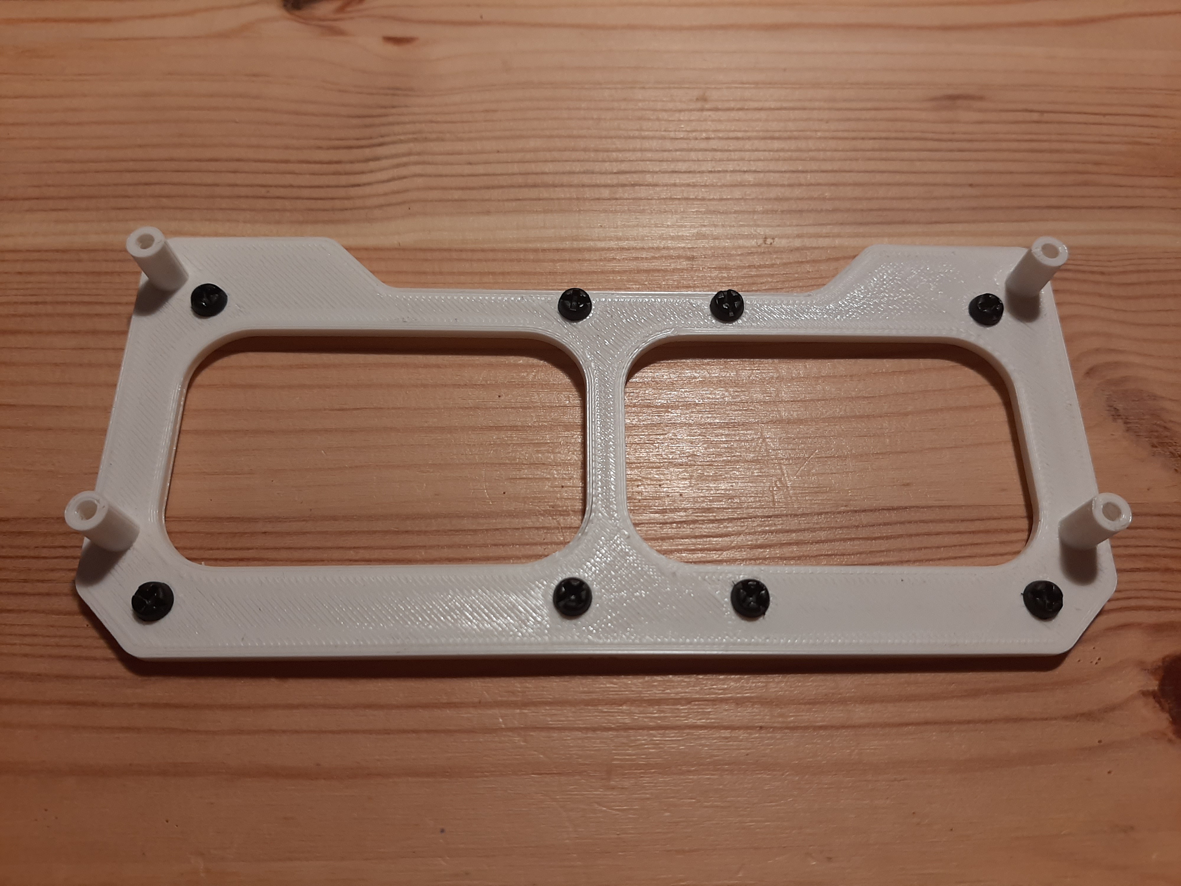
Screw the 8 6mm screws into the support frame:
![]()
Then add 6 regular 5mm spacers and two with the screw end to the other side of the support frame:
![]()
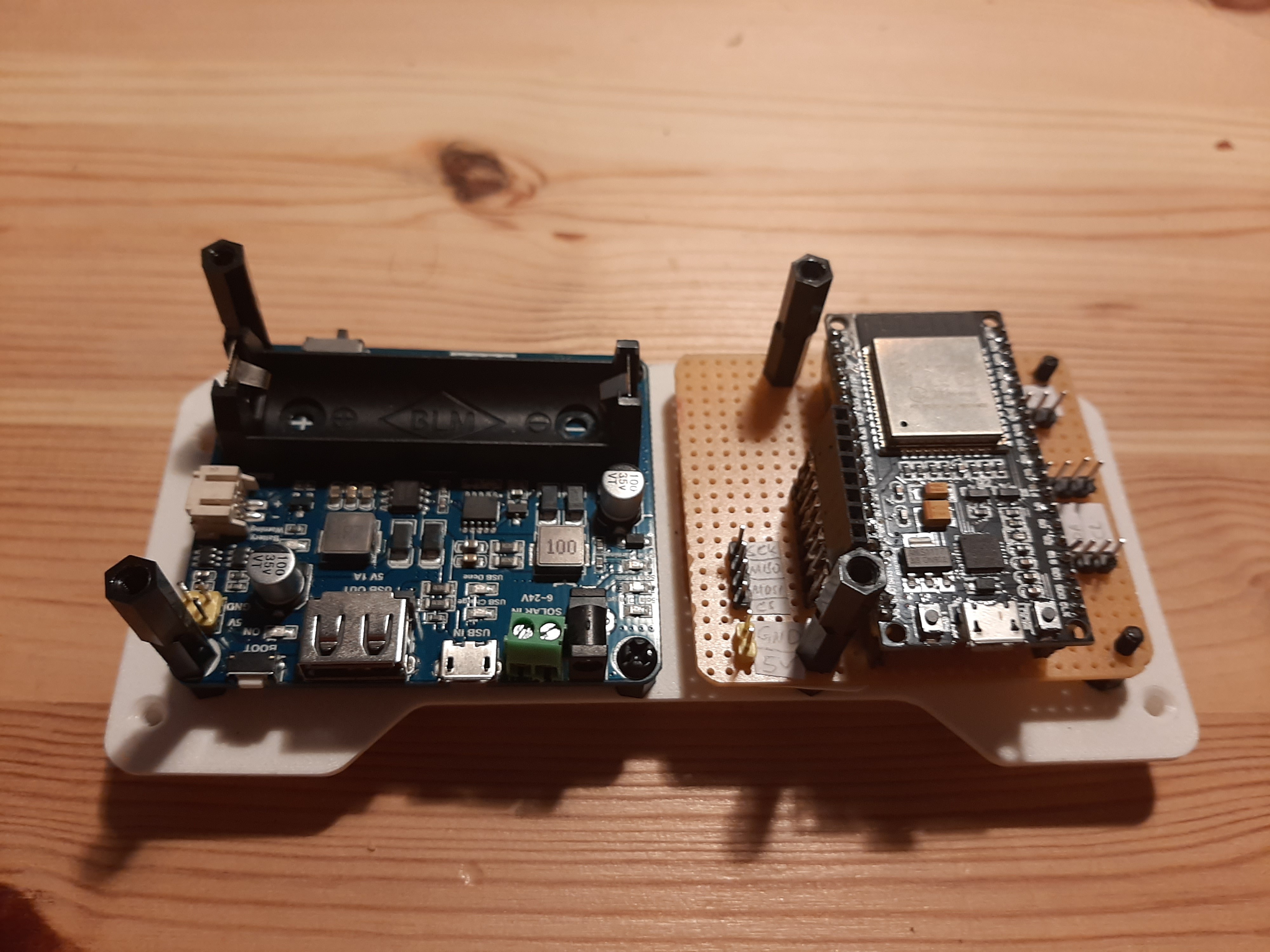
Add the solar power management unit to the left side of the supply frame. Use 4 of the 15mm spacers (always two on top of each other) for the left side and two 6mm screws to fixate the right side:
![]()
Now ideally we would use a PCB board for the next step, however I wanted to show that we can also just use good old fashioned perforated grid board here. Please note that the pin sockets for the display are elevated by 30mm to receive the display without the necessity of a cable (central picture):
![]()
Now we can also screw the second board into place using 4 15mm spacers and 2 nuts that are not displayed in the picture here for the right side:
![]()
Now we can add the ESP32 board that should just slide smoothly into place:
![]()
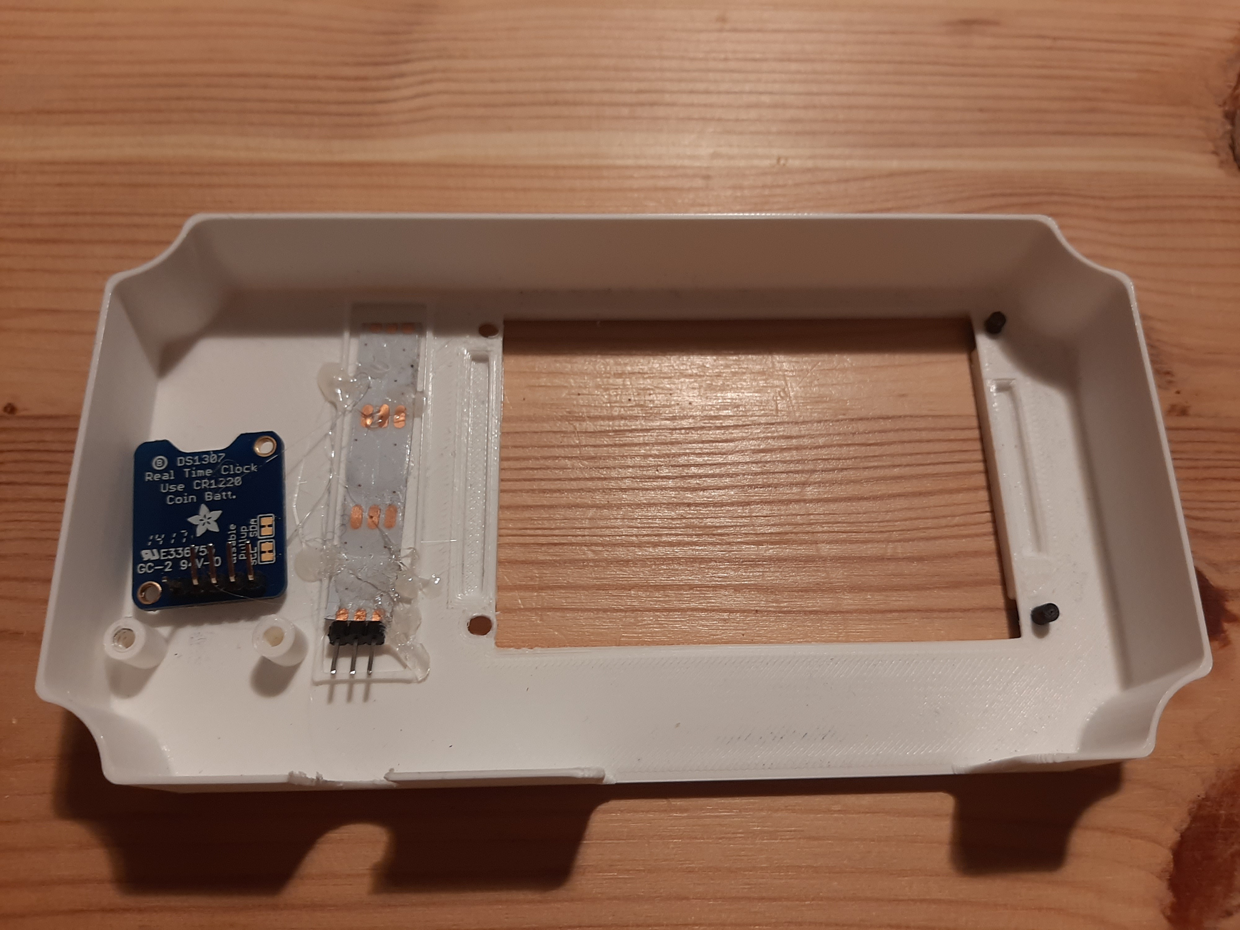
Then we can prepare the cover piece, adding the Neo-pixel strip and the real time clock. I used hot glue, you can of course also use tape or screws:
![]()
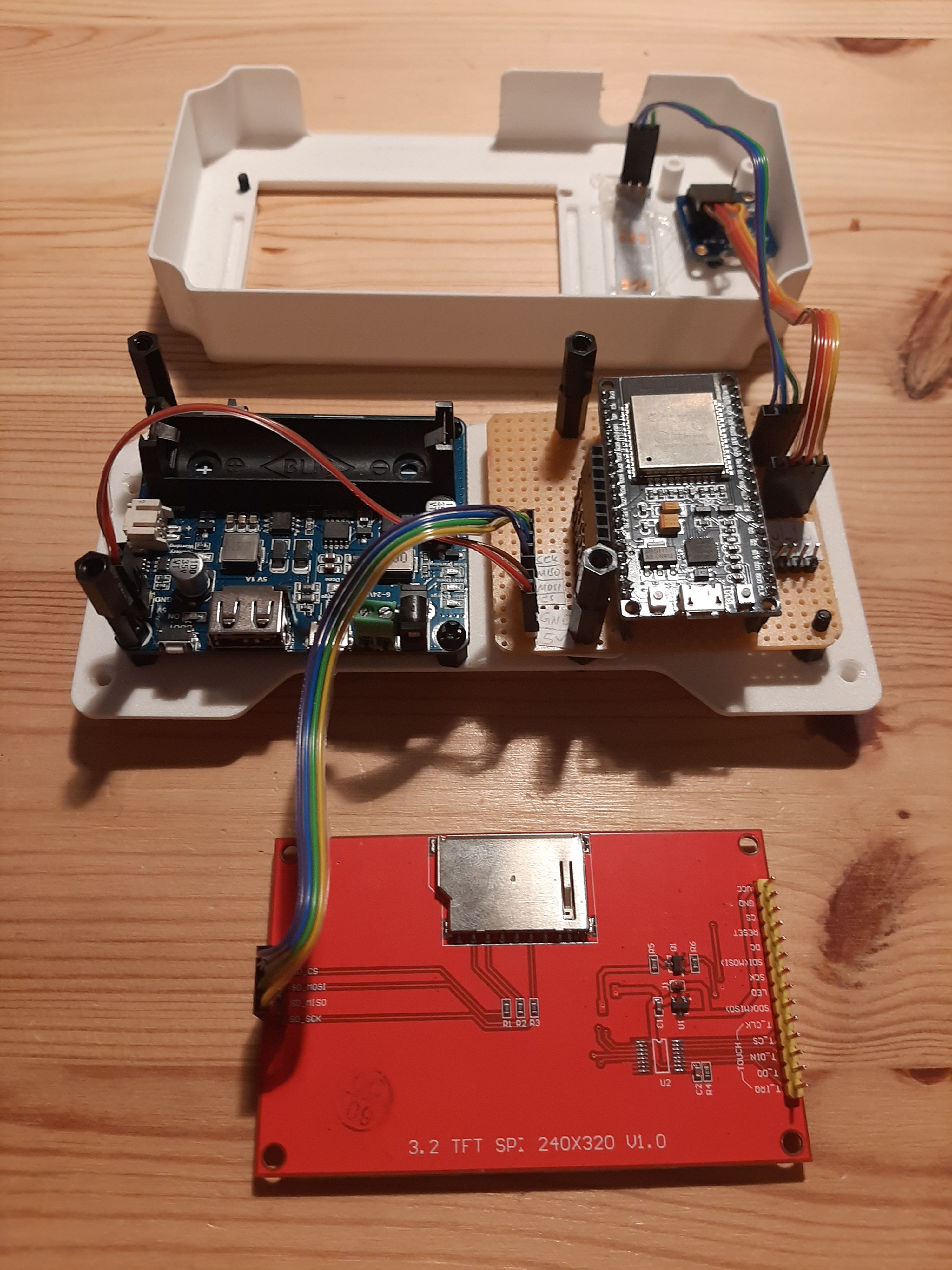
Connect both components with wires to the main board:
![]()
We further add a power supply wire between the solar power management board and the main board, and also add the cables for the SD-card slot on the display board:![]()
Finally the display pins are connected to the elevated receivers. If these receivers are exactly 30 mm in height, the display will be easy to connect. Note that this is just a suggestion to avoid the necessity to use a very short cable to connect the screen:![]()
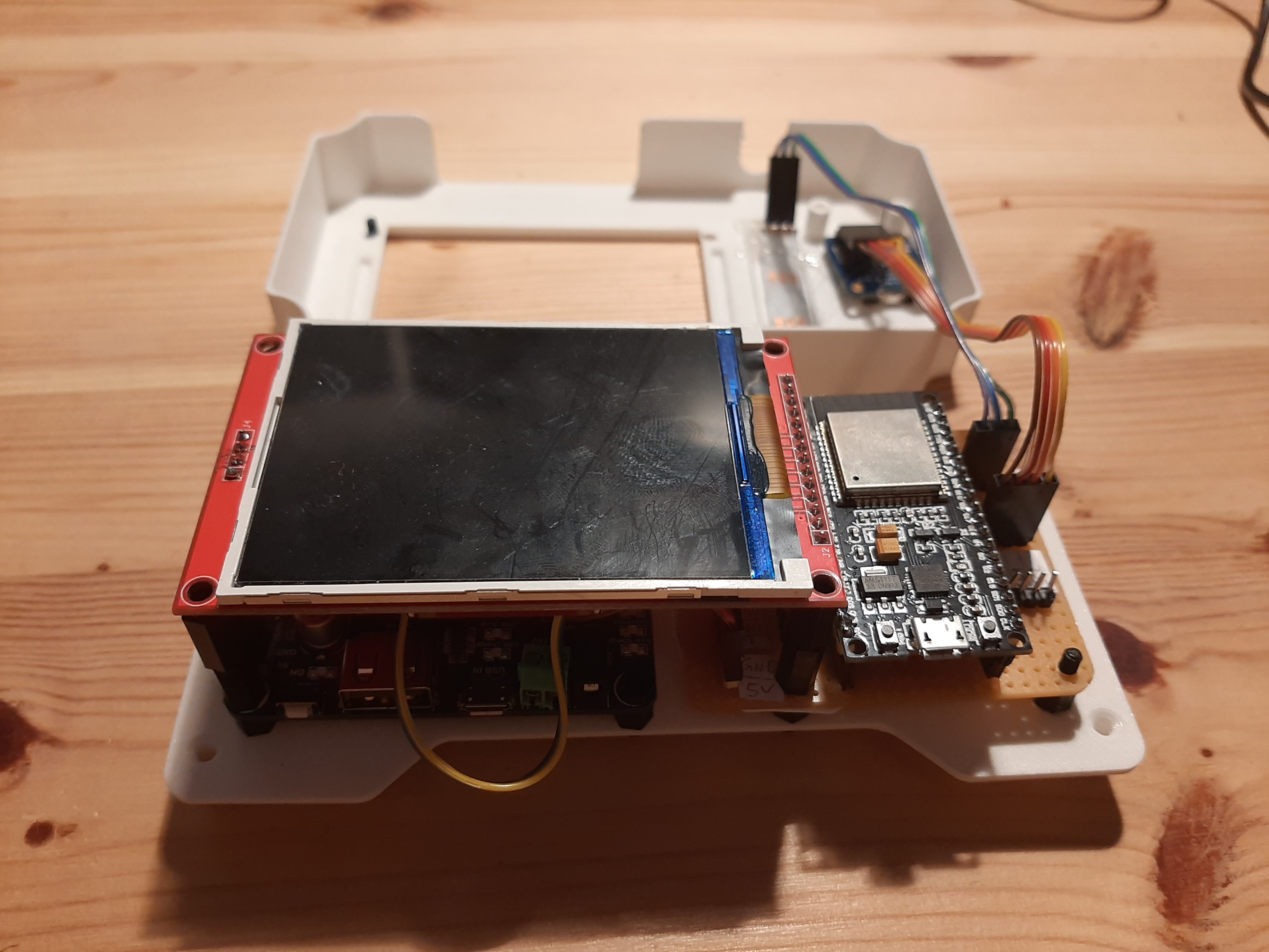
The display can then be mounted on the assembly:
![]()
For the next step, I forgot to take enough pictures, so here is a small summary: I use a 158x90x60 mm water proof, semi-transparent box to house the battery and the main interiors of the sensor system. We have two cables connecting the box with the thermal camera and the solar panel. These cables have to enter the box on the lower side. To make this water tight and dust resistant, I used two cable glands to seal the cable entries to the box against humidity. For these cable glands, two holes have to be drilled into the box.
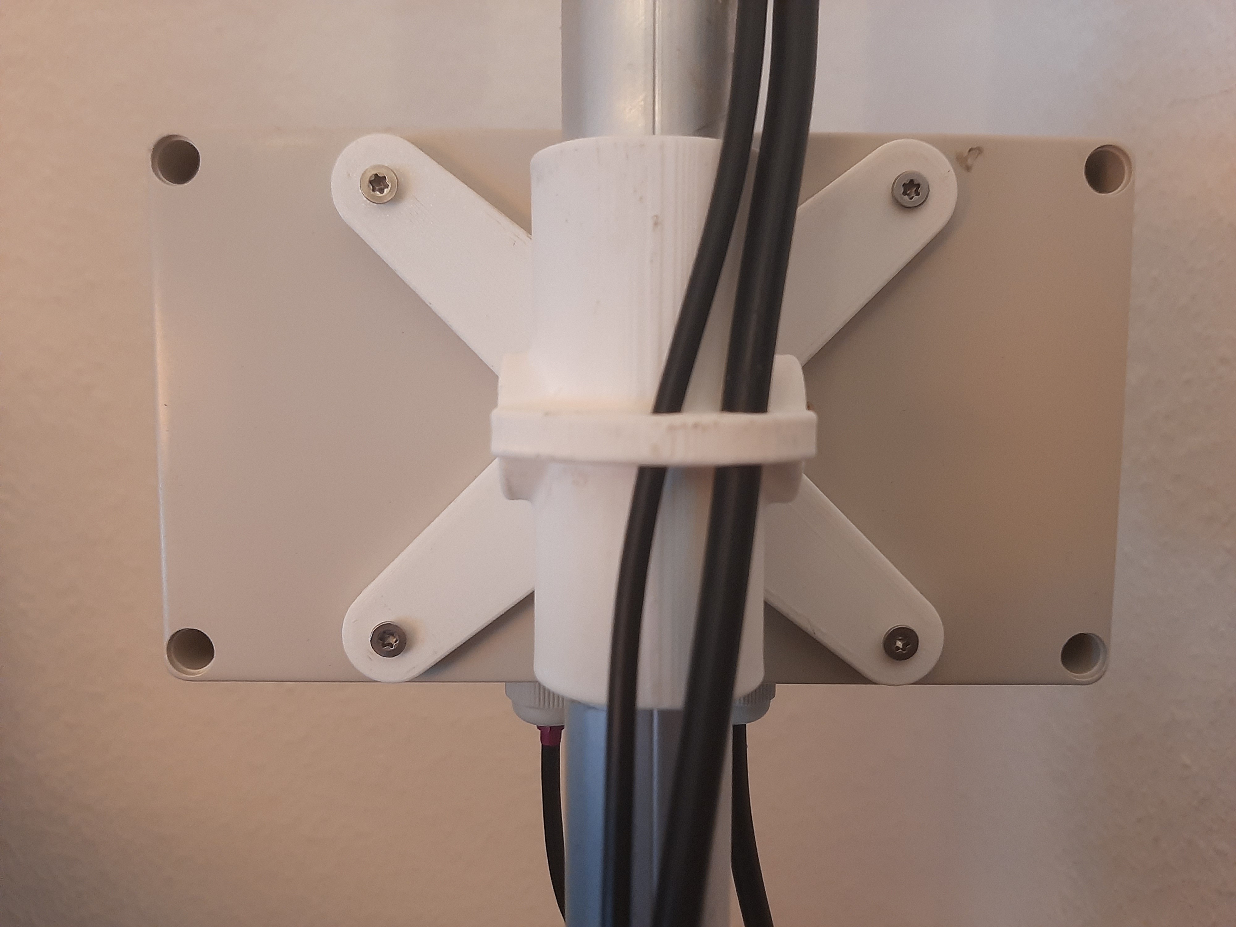
When both holes are drilled, the cable glands are inserted loosely and the attachment X is added to the backside of the sensor box. I used Torx-screws, however, any screw should be fine here. In the picture below, you can see the setup with both cables already in place.
![]()
Now we can add the cables for the solar panel and the thermal camera through the cable glands, as you can see in the picture below. Note that I added a connector to the camera cable so that it can be easily connected to the main board via the pins. Further I use double sided tape to glue the battery in place.
![]()
With the battery installed, it is now time to add the main box component that we assembled before. First I connect the solar panel cables and the battery cable to the power management unit. Then, I use four Torx-screws to attach it to the box. After the main component is screwed in place, it is time to connect the thermal camera cable to the main board.
![]()
So far the screen is only attached via the pin connectors. In a next step, the cover plate that was resting above the box in the picture above is screwed in place connecting the screen firmly with the main box setup. This process is a bit fiddly, since the plastic screws and the 3D-printed holes are not perfectly round. I think you can save quite some effort here when using brass spacers and steel screws for the project.
![]()
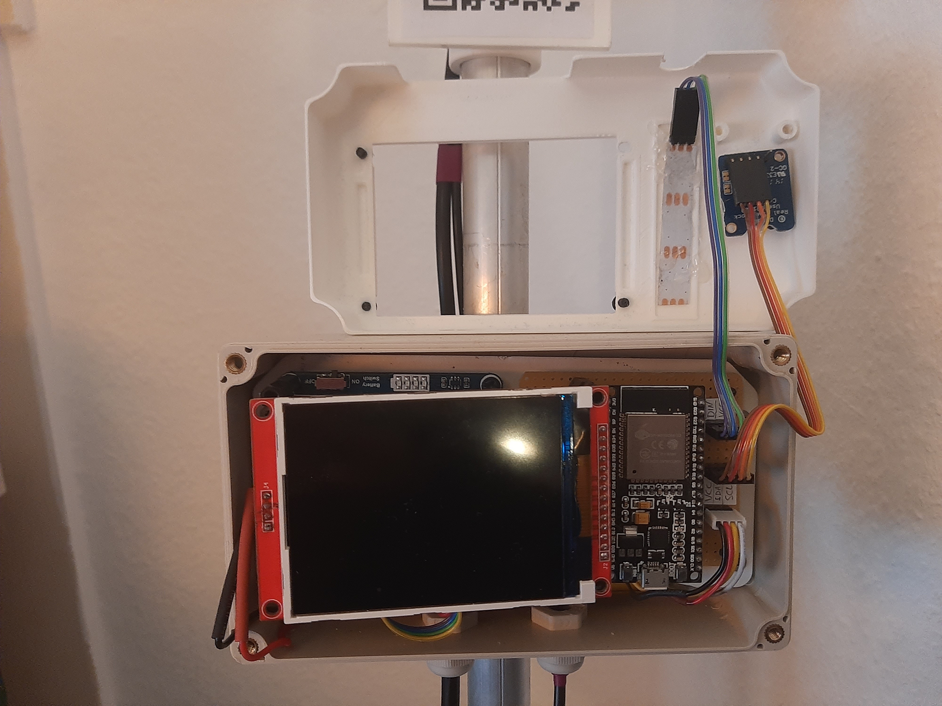
As you can see in the picture above, this should nicely fit into the sensor box and cover up the entire interiors of the sensor. This is now the best time to add an SD-card to the SD-card slot.
![]()
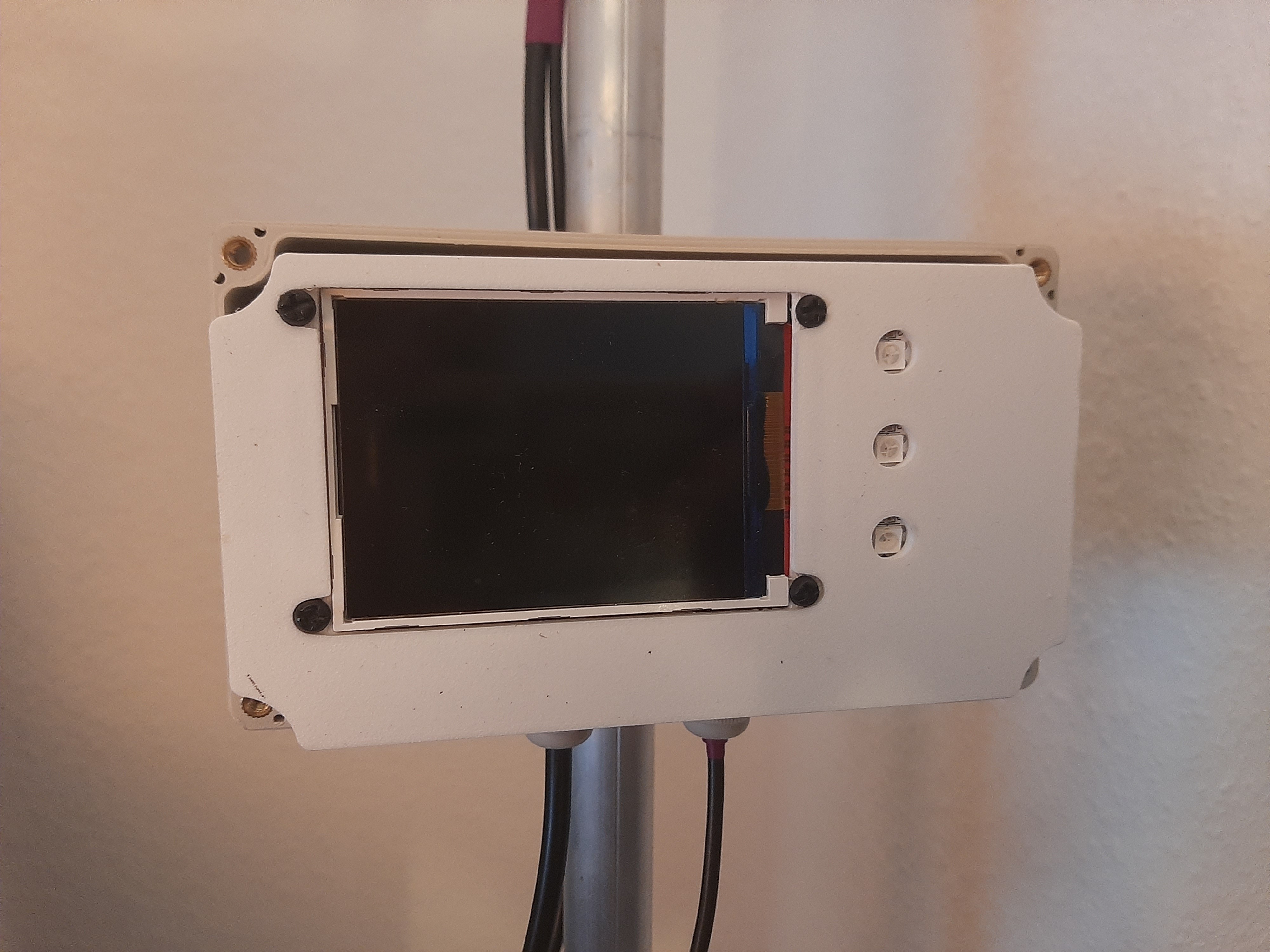
Finally the box can be closed carefully using four screws and the sensor box setup is ready.
-
3The thermal camera
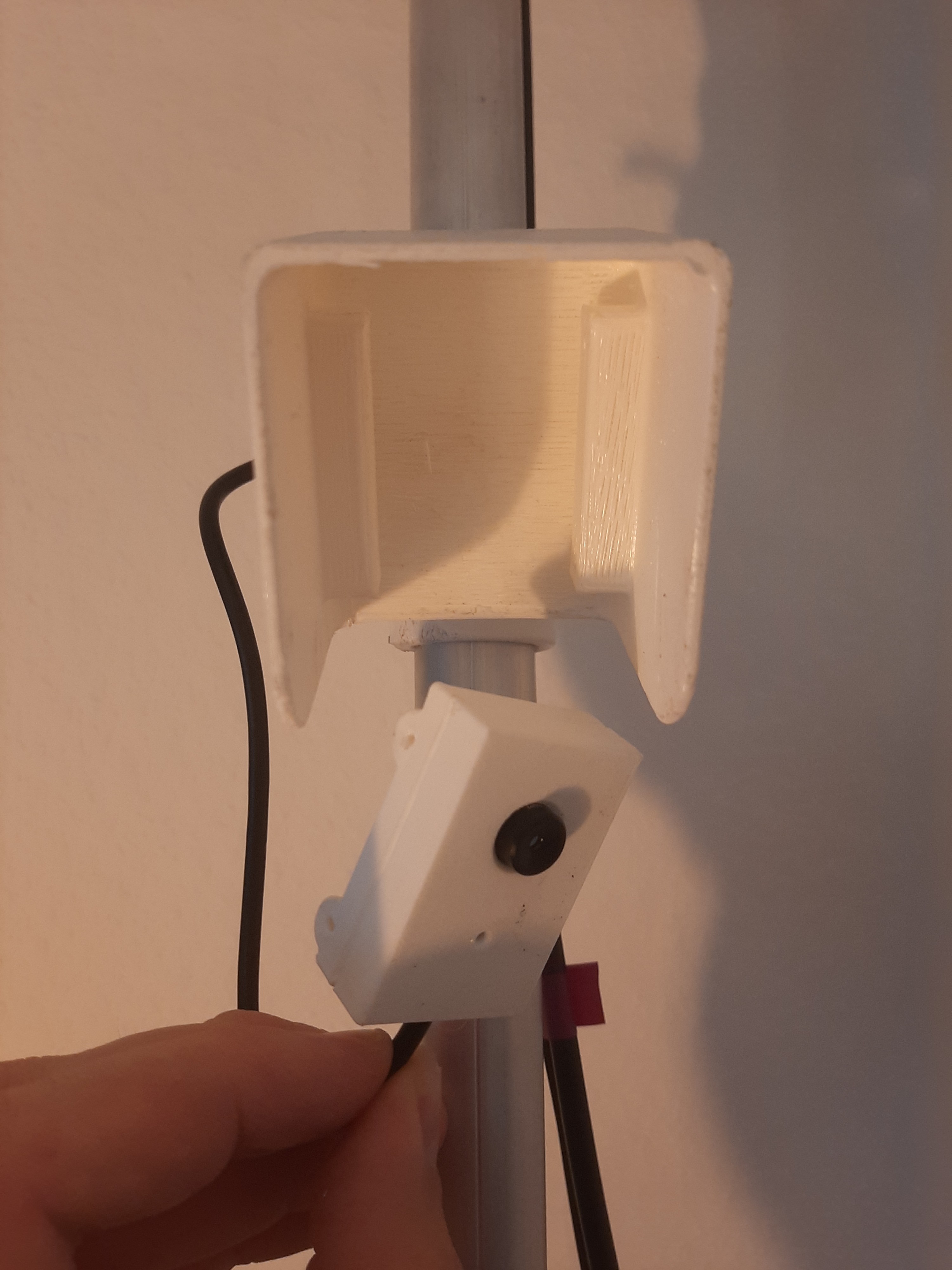
The thermal camera is the actual sensor of this sensor system. For this prototype the camera case was 3D-printed in white and covered with several layers of clear coat. However, for my tests, it was very dry outside and this setup might not survive several month outside with strong rains and intense sunlight. I'm seeking to improve this in future versions.
![]()
The thermal camera is connected to the four wires of the cable leading to the main sensor box. Then the two pieces of the camera box are glued in place. I sealed them with clear coat too. However, this camera box needs quite a bit of improvement in the future. I thought about using a professional camera case and remove the front cover glass (since the thermal camera cannot be covered by glass). The camera is then attached to the camera shield using four Torx-screws.
![]()
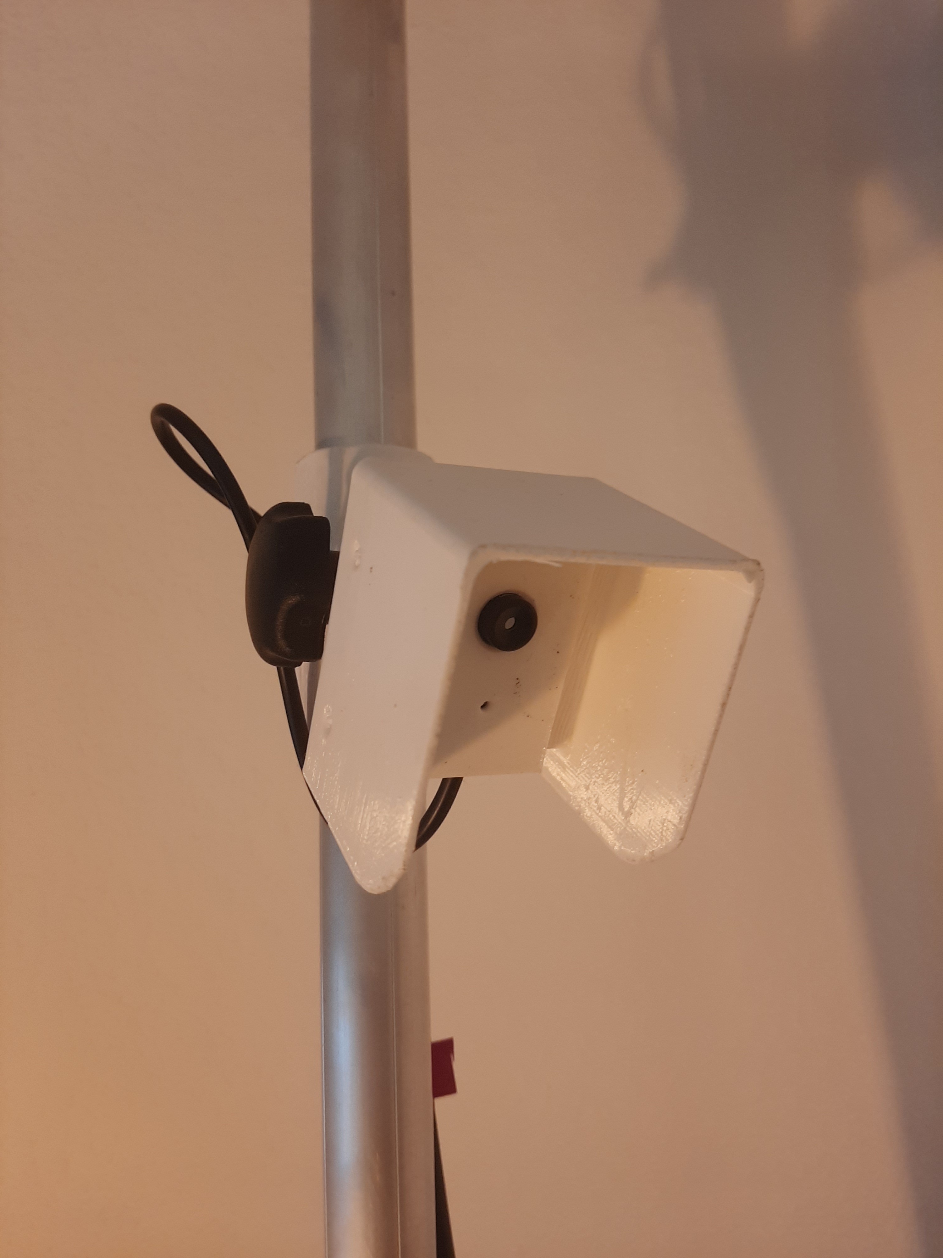
The final camera setup should look like this. I use a 45° angle to position the camera and a black plastic coated screw to adjust this angle.
-
4Assembly of the solar panel
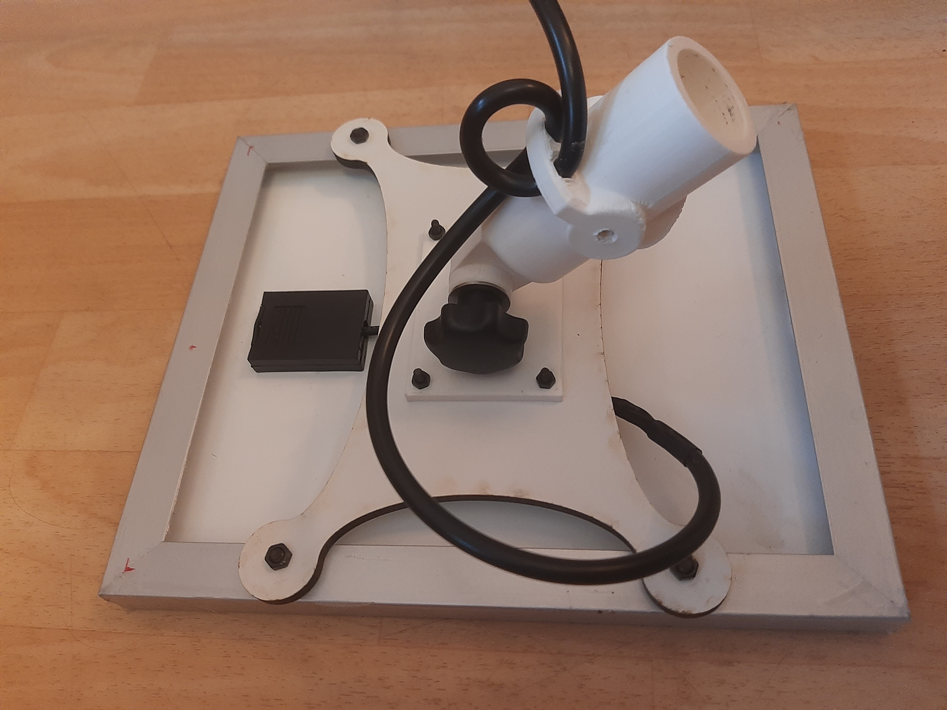
The assembly of the solar panel is very simple. First the cable from the sensor box is cut to a good length. Then the cable is fixated using the wholes on the backside of the solar panel attachment tube to avoid tension on the cable. The cable is then soldered to the solar panel's backside and the small black cover is attached again. I use shrinking tubes and tape to make this connection as water tight as possible. However, if you want to make this perfect, you should add some silicon to fully fill the small black box on the solar panel and to make it fully watertight.
![]()
I asked my local maker space to laser cut the solar panel back plate from a composite material (and I forgot to ask which one). I then added the 3D-printed parts using four machine screws and one of the black plastic covered screws to be able to adjust the angle of the solar panel later. Then I used four screws to attach the solar panel to this support structure.
In the German Make magazine 3/22 a weather station setup was shown using similar components. However, in this setup the battery and charge controller were attached just below the solar panel. I think this is an alternative way to build this sensor. Personally, I'm much more comfortable with including the battery in a water proof case and not place it just below the solar panel. These batteries are very, very heat sensitive and might get damaged just below a hot solar panel in summer.
-
5Field ground fixture
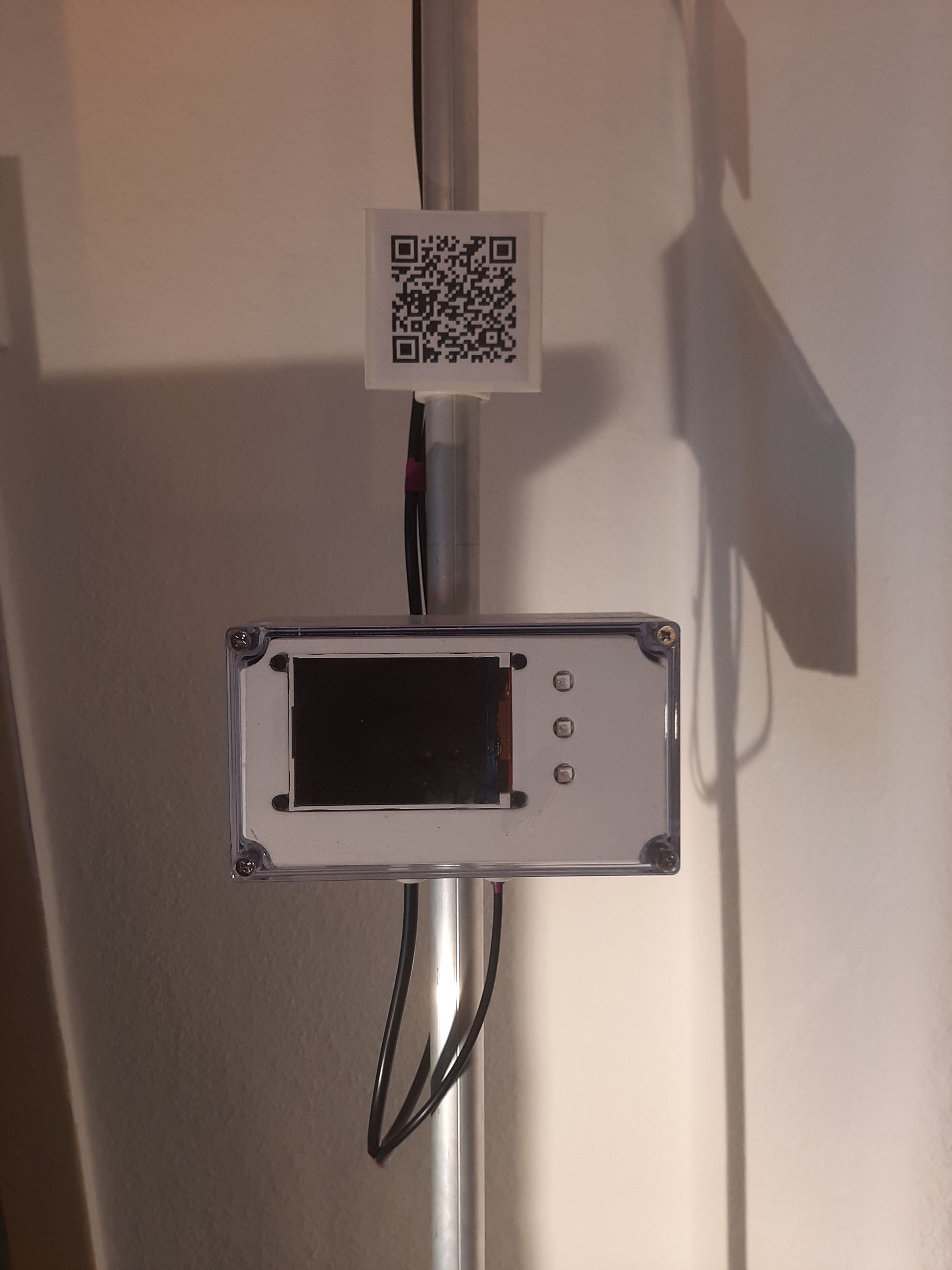
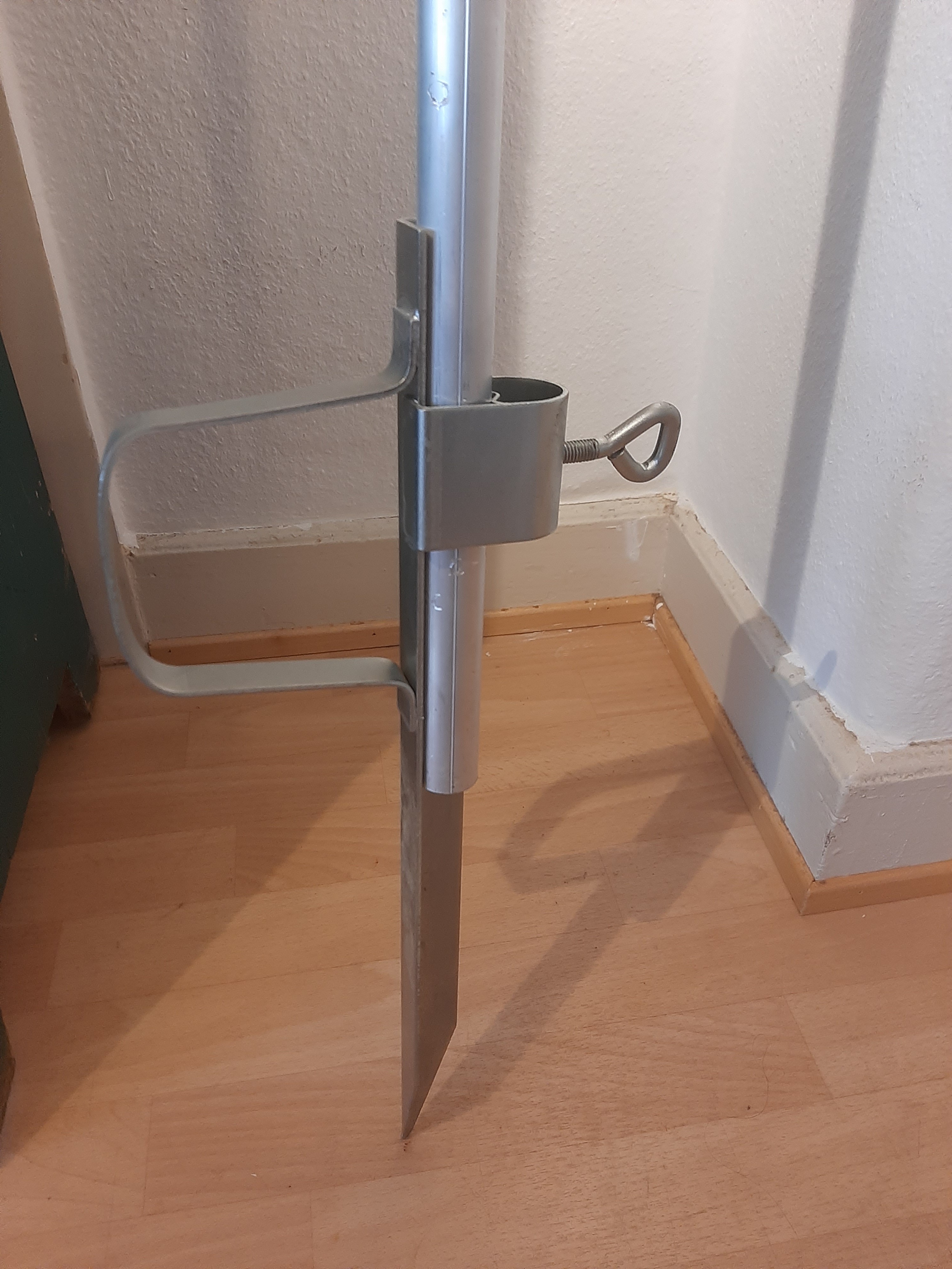
This section is usually neglected by most outdoor projects. I think it is very important to also talk about ways to set up the sensor in the field. For this sensor I had two options: A concrete block style or a "ground needle" style sunshade stand. I mostly use sunshade stands for outdoor projects since they are easy to find and usually don't cost too much.
![]()
For this project I decided to use a "needle" type that cost around 10€ in my local hardware store. With these stands it is quite easy to transport the sensor to the field - even without a car - and the metal strip that is attached to one side helps sinking this assembly even into dry soils. The entire sensor has a weight of 6-7 Kg and is positioned solidly with a sunshade stand like this in the field.
-
6Future improvements to the Crop Water Stress Sensor
I'm currently working on different improvements to the sensor:
- I added LoRaWan to the sensor already (using the SPI bus) and I'll add a bigger update on this in the next weeks.
- Now that the days are becoming shorter in Germany, the visibility of the screen is not a big concern anymore. However, in full sunlight during summer, it would be better to use an E-ink display. I didn't find E-Ink displays in the same size, but I'm currently connecting a 2.8 Inch black & red two color display to the sensor. I'll keep you updated on this.
- An on and off switch that is easily reachable in the sensor box with the transparent cover off. So far, I'm using a thin screwdriver to switch the sensor off and on because the switch on the charge controller PCB is quite hidden.
- An additional air temperature sensor that can be added to the sensor box, measuring the air temperature below the box will improve the measurements of the crop water stress index.
- I also thought about adding a positioning display mode. If the transparent box top is off, a push button on the lower side of the mainboard can be pushed and the display could then display the camera output as a picture. This way a precise positioning of the camera (covering plants and soil in the field of view) is possible.
If you have further ideas for improvement, please just write me! I'm always happy to improve this sensor.
-
7adding LoRaWan (coming soon)
This is just a quick add on that works on my desk breadboard setup already. However, I'm not sure where to place the LoRaWan device best in the sensor box (above).
Currently I'm thinking about how to best place the antenna too and how to test the different setups. I have basically two options, either placing the antenna below the bottom of the box, using one of these plastic antennas with the practical screw threads or extending the antenna up to the solar panel (or even higher). The antenna attached to the bottom of the sensor box would definitely make the setup more compact, however, this might reduce the range of the sensor. Since I plan to use these sensors also far away from the LoRaWan-gateway, I think I'll have to put the antenna on top of the solar panel. I'm currently looking for projects on how to extend the antenna of a LoRaWan transceiver. I'll keep you updated here.
-
8experimenting with different screens (coming soon)
Obviously for good visibility and low power requirements, the 3.2" Inch ILI9341 display is a bad choice. I ordered a few e-ink displays to conduct a few experiments here. However, this will be difficult since the days are becoming shorter here and these mid summer full sunlight conditions will not be there for tests until next summer.
-
9Additional on/off switch (coming soon)
I ordered nice switches and this might be completed in the next days/weeks!
-
10An additional temperature sensor (coming soon)
A small article on this project was also posted on hackaday.com. The comments were right that the thermal camera ideally needs a reference temperature sensor. However, the commentaries claim this sensor has to be on the ground, which is only one alternative. Coming from a remote sensing in agriculture background, I know that the ground reference for the Crop Water Stress Index is usually taken from air temperature measurements. I'll use a water proof sensor either in 2m altitude above ground (as it is standard for these measurements) or below the sensor box, as this would just simplify the setup. Stay tuned, I'll write some updates here.
Crop Water Stress Sensor
This sensor measures crop water stress using a thermal camera and communicates drought inflicted crop damage to farmers and a wider public.
 Florian Ellsäßer





Discussions
Become a Hackaday.io Member
Create an account to leave a comment. Already have an account? Log In.