Nicolas REIMEN
-
Testing and Cleaning Up Soviet Chips
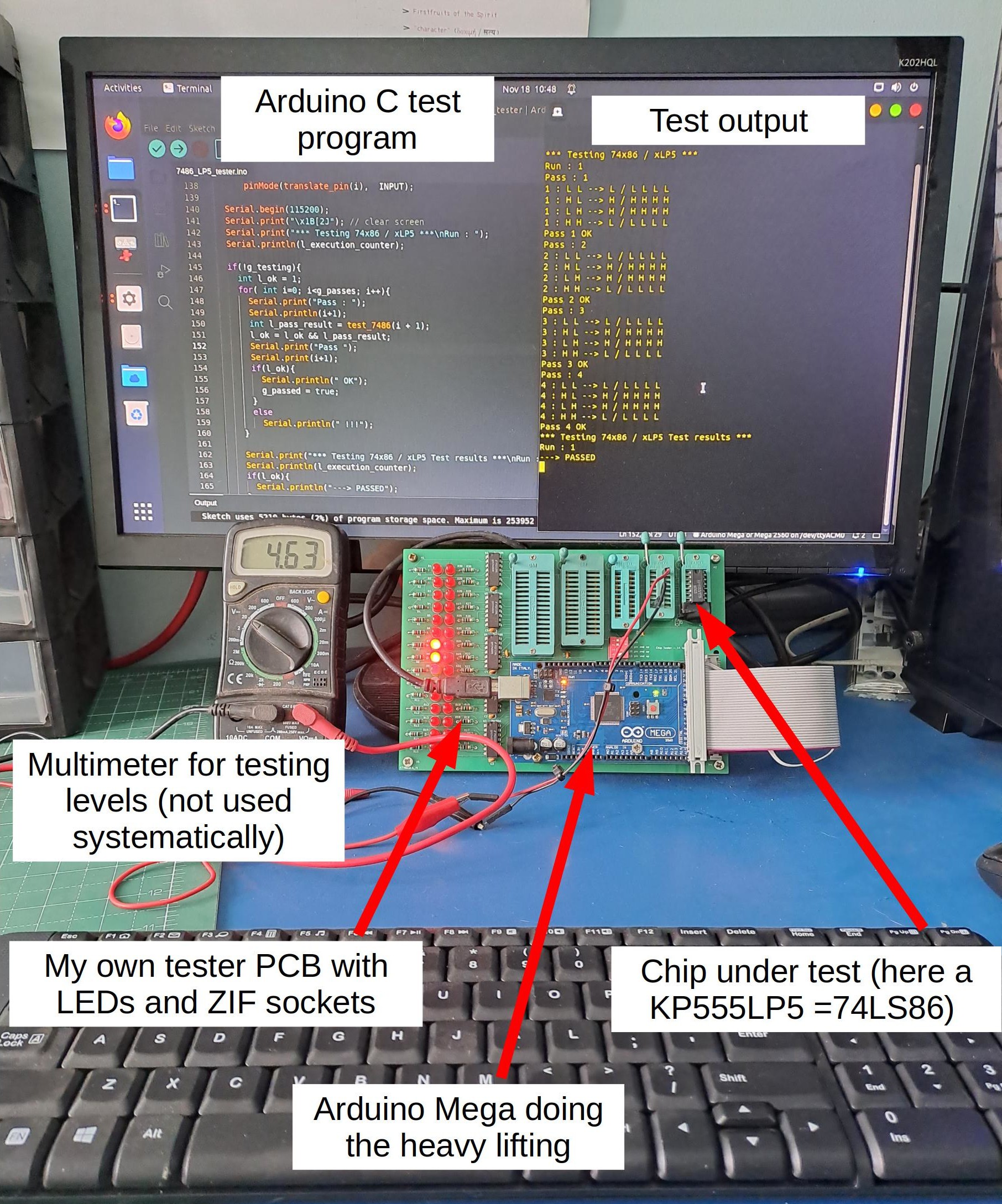
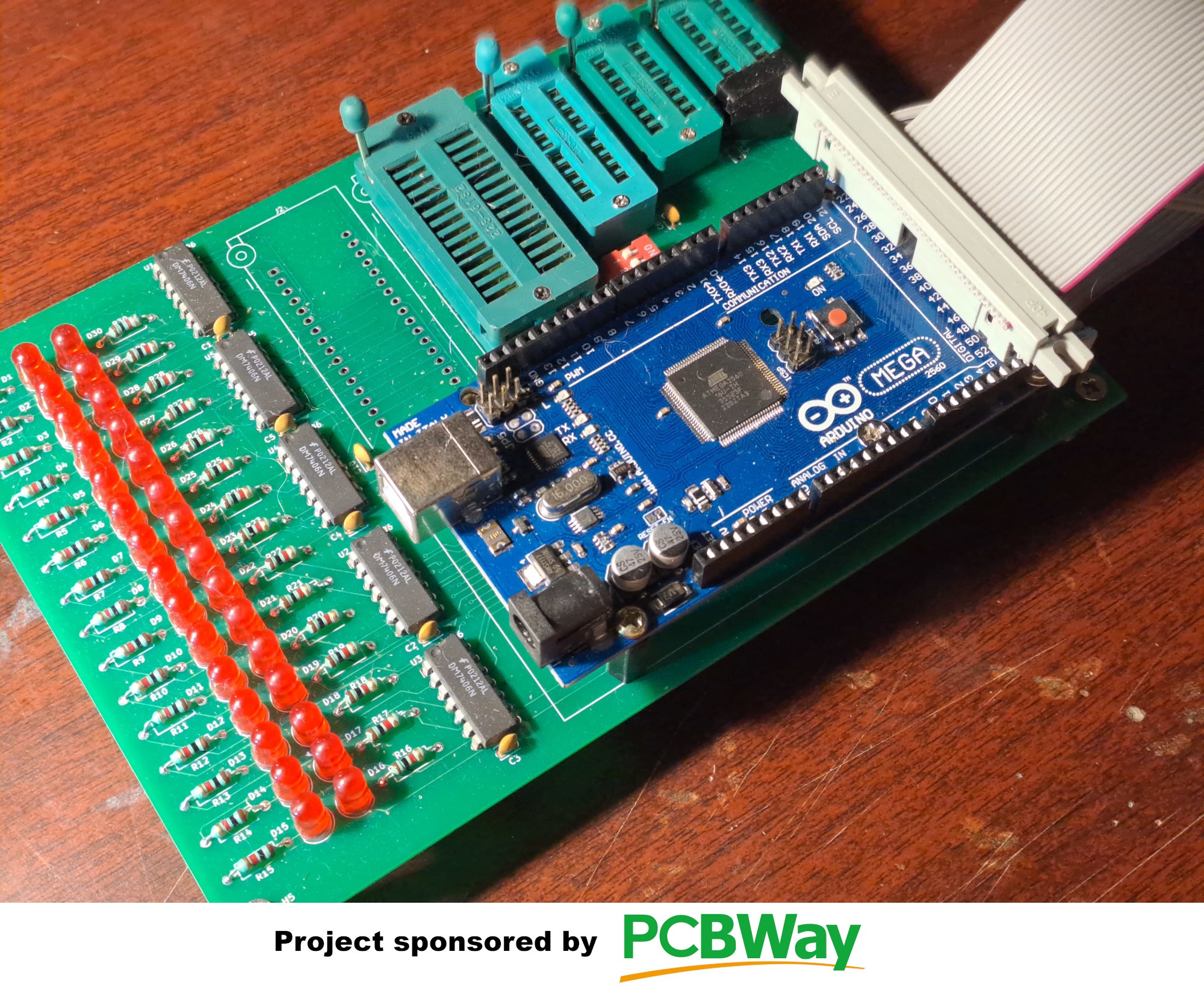
11/18/2022 at 06:21 • 3 commentsHello fellow retrobrewers. Since the Soviet clone chips I was able to source from ebay are new old (old) stock, and have sometimes been stored for decades in less than ideal conditions, they all need to be tested. Here is my testing rig:
![]()
Each chip model has its own test program that I upload into the Arduino before testing a batch. The tester PCB has ZIF sockets from 14 to 32 pins, which allows me to test all types of TTL chips and also large SRAM chips (I will use the very common 512kx8bit size). The Arduino board is connected to the tester PCB through the big grey ribbon cable on the right. The output you see above the tester on the right-hand side of the screen shows 4 successful passes of test for a quad XOR gate chip (KP555ЛП5 = 74LS86).
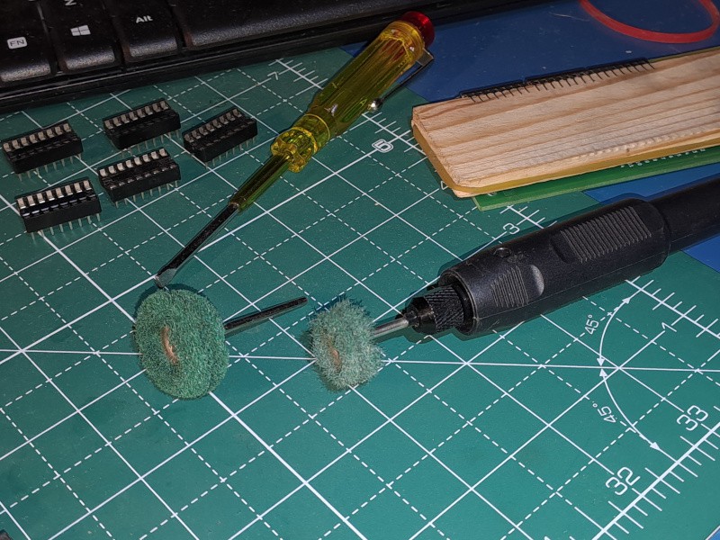
Some of the Chips I received (from Ukraine, no less) had been stored not so well and their legs were badly corroded. Therefore, I had to find a solution to clean them up. After searching on forums and such, I decided to opt for mechanical polishing using a Dremel-type grinder and these kinds of brushes:
![]()
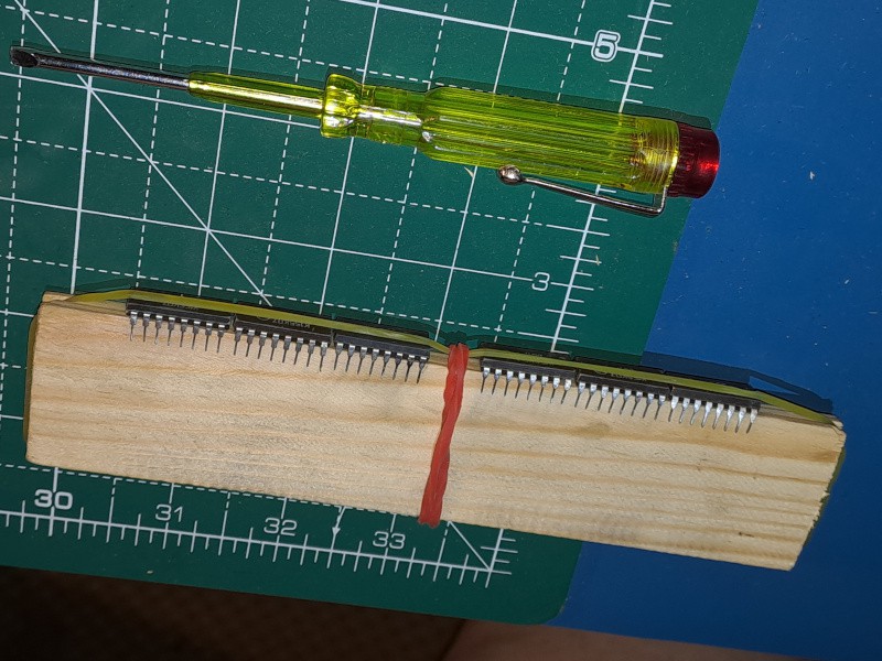
On the left is a new brush and on the right, the way it looks like after polishing a dozen chips. They wear out fast. The material they are made of is similar to scotch-brite pads. In order to hold the chips while polishing them, I used the rig below:
![]()
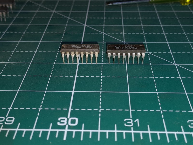
This enables me to polish 6 chips at a time without risk of damaging them. Here is a before/after picture:
![]()
The pin corrosion was bad enough to prevent any electrical contact and thus made the chips fail the test. After cleaning, all passed but some needed to be socketed to reach that goal. The reason is that ZIF sockets grab chip legs from the sides, which my method is not always good at cleaning. By contrast, ordinary sockets establish contact on the front and back of chip legs, which are properly polished by the Dremel brush (actually only the front, but that is enough).
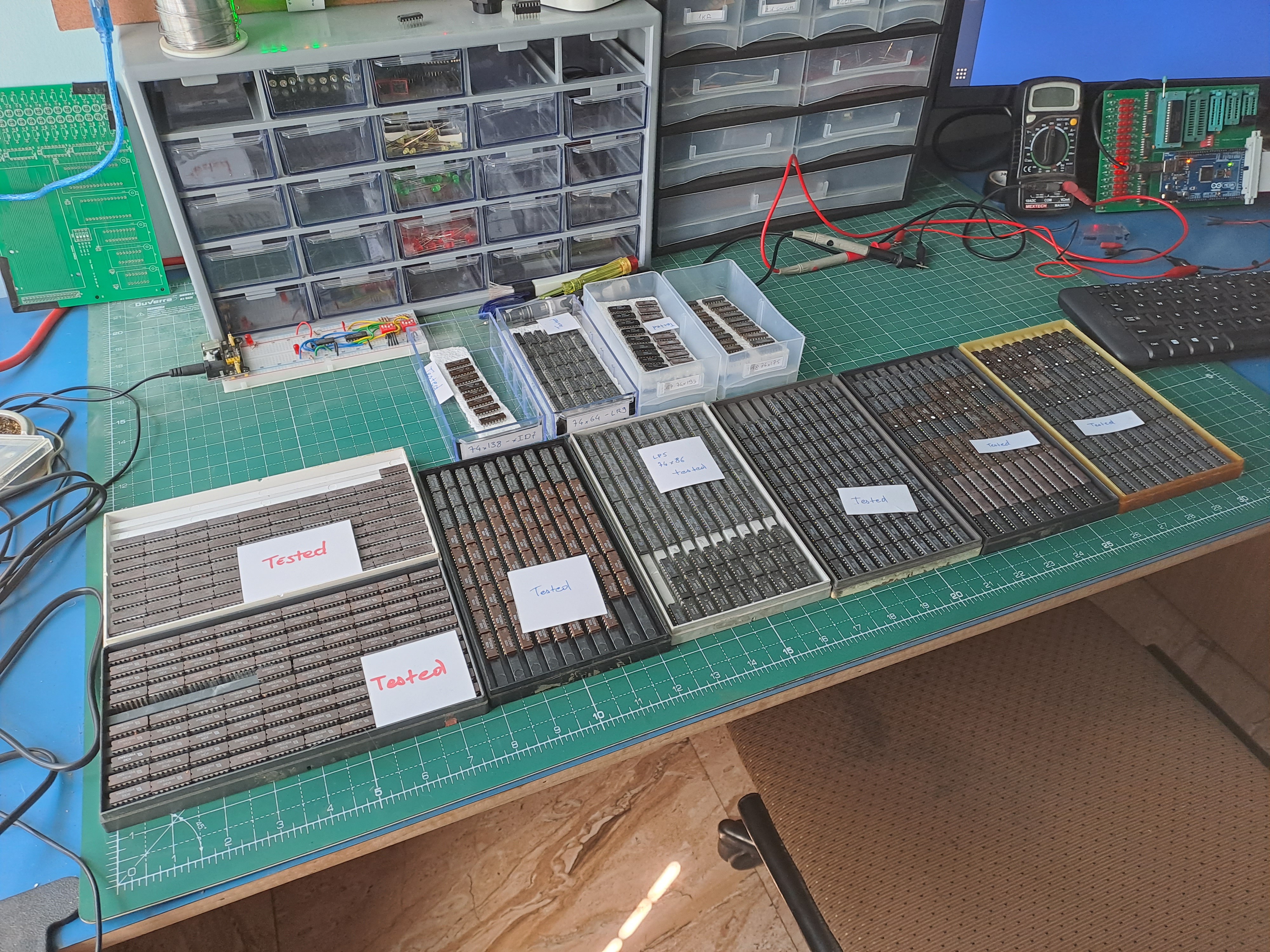
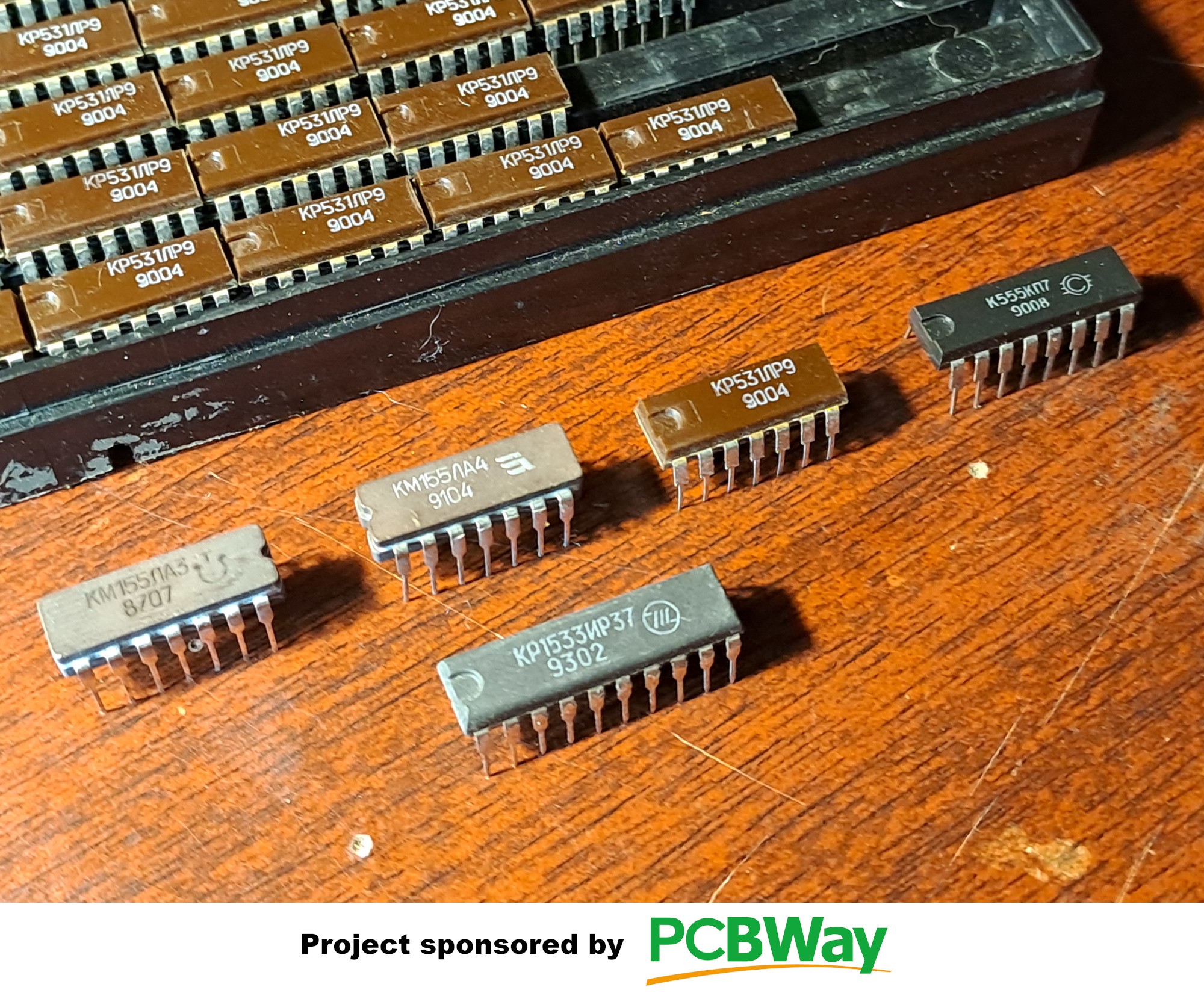
Here is a picture of my complete collection of Soviet TTL clone chips as it stands now:
![]()
The inimitably crappy Soviet-style plastic trays I received most chips in are really cool in a vintage Chernobyl miniseries kind of way (wonderful series btw, strongly recommended). From left to right, we have:
- KM155ЛА3 = 74LS00 (ceramic, top tray)
- KM155ЛА4 = 74LS10 (ceramic, bottom tray)
- K555ЛР9 = 74LS64 (plastic)
- K555ЛП5 = 74LS86 (plastic)
- KP555ЛА3 = 74LS00 (plastic)
- KM155/K555КП7 = 74LS151 (plastic and ceramic, last 2 trays) The chips with a white corrector fluid dot on their asses are those which failed the direct test but passed when socketed after polishing.
In addition to the trays, the 4 plastic boxes on top contain (from left to right):
- K555ИД7 = 74LS138 (plastic)
- some more K555ЛР9s
- K555ИЕ7 = 74LS193 (plastic)
- K555ТМ8 = 74LS175 (plastic)
The ЛА3s, ЛА4s, ЛР9s and ЛП5s will be used for glue logic and the ALU (similar to the 74181 replica I already built). The ИЕ7s (up-down 4-bit counters) will be used for the uPC and the SP). The ТМ8s (quad D-type FFs) will be used for the other registers. The КП7s (8-to-1 multiplexers) will be used for the cross-bar switch connecting everything inside the processor and the ИД7s (3-to-8 selectors) will be used for address decoding and such.
-
Multiplexer PCBs just arrived (great stuff)
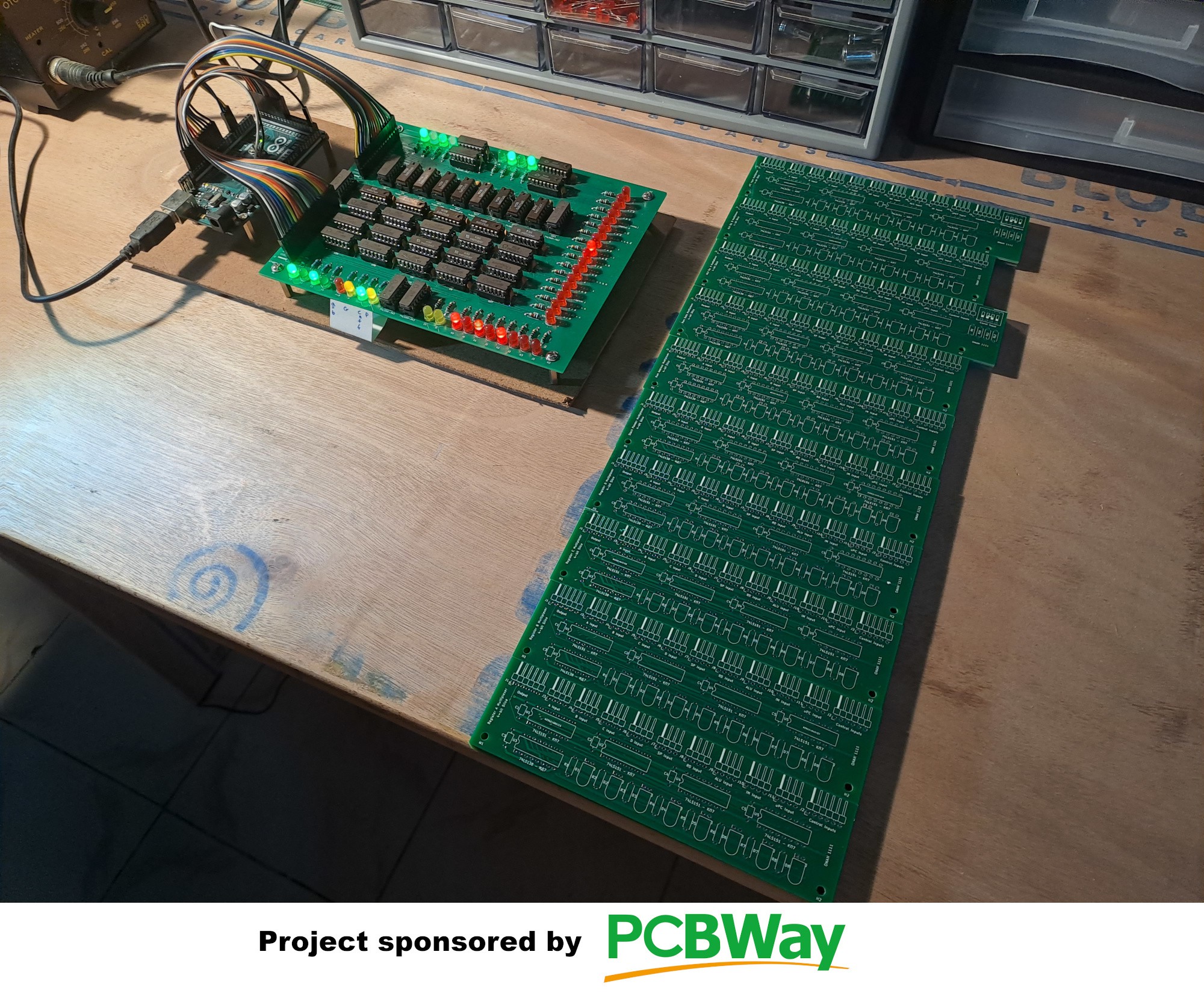
09/30/2022 at 07:38 • 0 commentsThe multiplexer PCBs for the crossbar switch have just arrived. Here they are:
![]()
These were sent free of charge by PCBWay as part of the sponsorship deal.
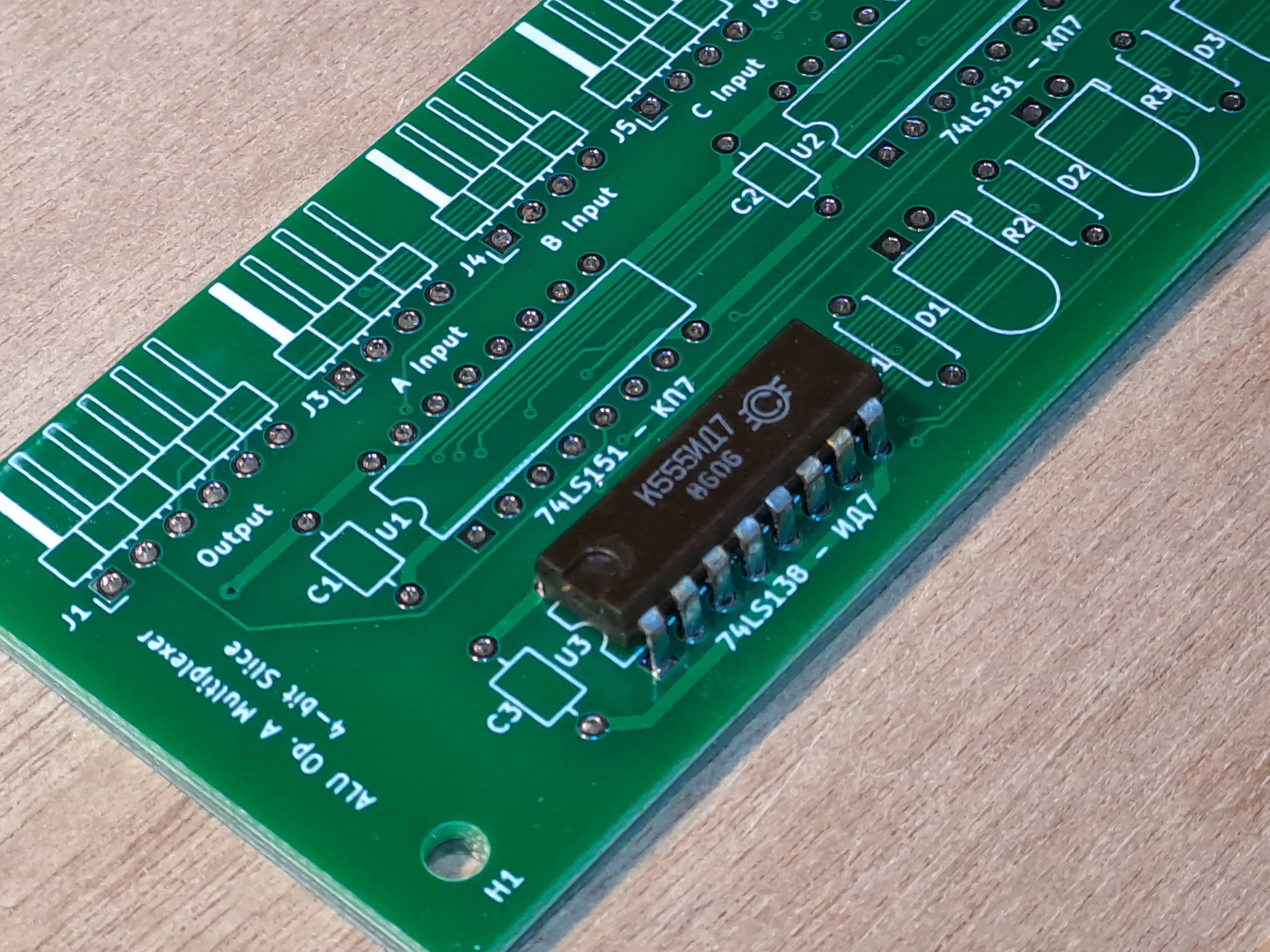
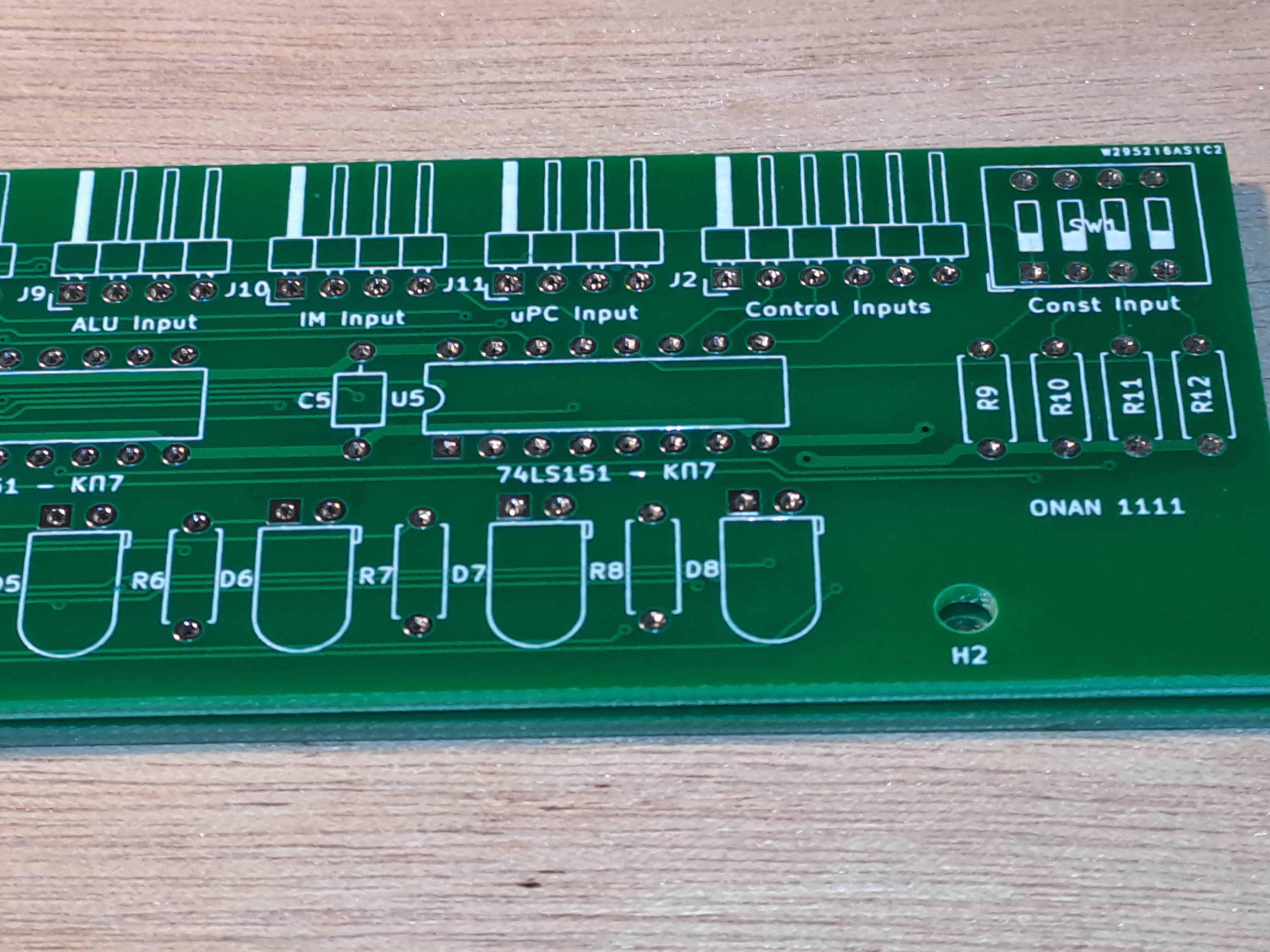
They are of excellent quality. Before that, I had ordered my PCBs from "another supplier" (blink-blink, hint-hint, everyone knows who I am talking about, right?). The PCBs I just received are much better. I think anyone can tell just by looking at the picture and comparing it to the previous ones in the project logs or on the main page. Everything looks better, the silk screen lettering, the solder mask, the tinning of the pads, ...
![]()
![]()
As I said, a retrobrew machine is a work of art and it makes a lot of sense, therefore, to have gleaming PCBs like these.
PCBWay's website is also quite nice and convenient to use for specifying the order and following its progress. They even have a feature that allows you to follow the PCBs as they go through each step of the fabrication process. Practically, I think it is totally useless of course, but it is super cool. Nice touch!
-
Crossbar-Switch PCBs on the way
09/20/2022 at 08:17 • 0 commentsThe 50 PCBs for the crossbar switch are on the way! (thanks to PCBWay) Wait a minute?! Did you say fifty?!
Yes, fifty.
The crossbar switch, the heart of ONAN 1111's design, will allow data to be exchanged between (nearly all) internal components of the processor on each clock cycle. It consists of ten 20-bit wide 8-to-1 multiplexers. Each multiplexer is split into five 4-bit wide slices. 10 x 5 equals 50. QED.
Each board will contain four 74x151 clones (К155КП7), for a total of 200. Each chip is a 1-bit wide 8-to-1 multiplexer. The boards will also contain 8 LEDs and a 74x138 clone (К555ИД7) to indicate which data-path is selected, when the processor is running in single-step mode or at a low clock speed. This alone will contribute 400 blinkenlights to the overall design. What is a retrobrew project without the blinkenlights ? ...
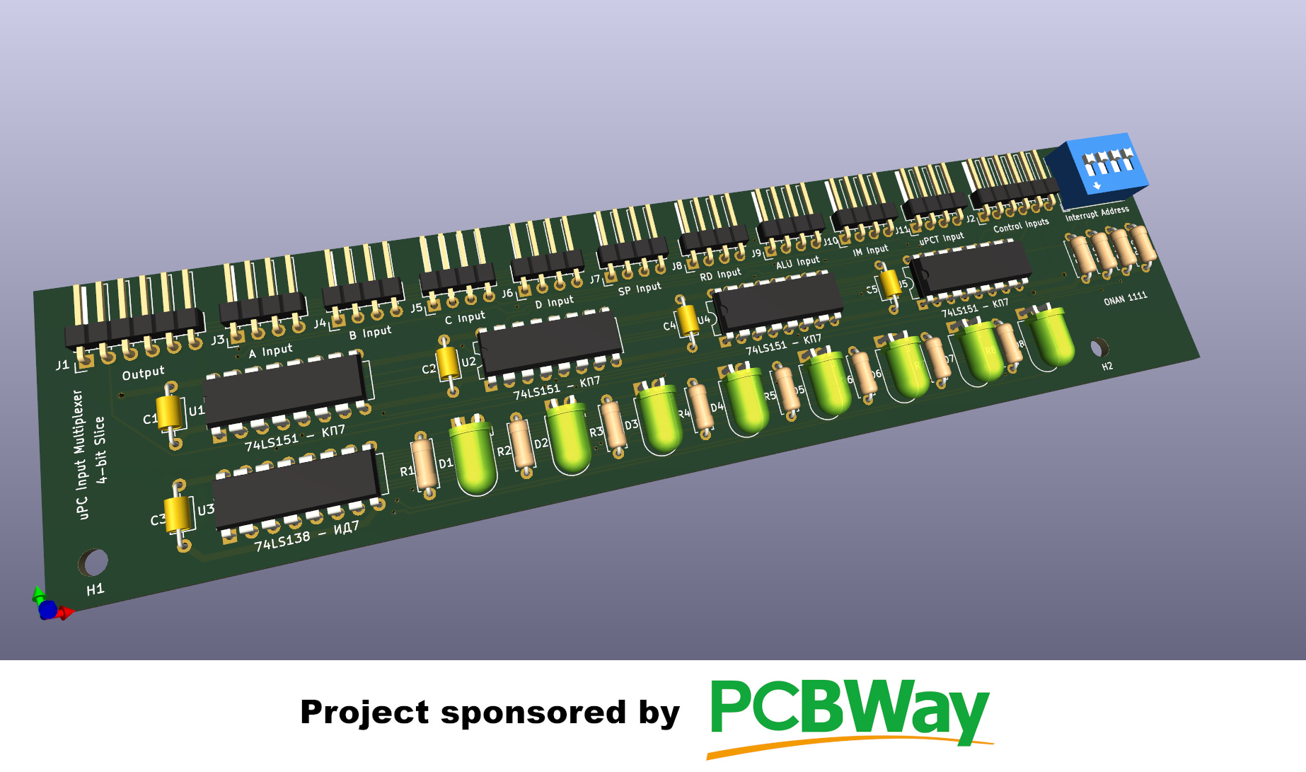
Below is a Kicad-generated 3D picture of one of the boards:
![]()
This one is the multiplexer that will feed a loading value to the microprogram counter (uPC) whenever necessary (jumps, interrupts, ...) The dip-switches will be used to enter the address of the interrupt-handling routine.
-
Support by PCBWay
09/18/2022 at 05:42 • 0 commentsThe online PCB company PCBWay has generously offered to support this project. I feel honored by this offer as PCBWay has supported a number of very cool projects in the past (notably, CuriousMarc's YouTube Channel). Many thanks to them.
![]()
-
People I look up to in the Retrobrew Community
09/06/2022 at 08:51 • 0 commentsAs you may have guessed, my all time favorite is Bill Buzbee and his Magic 1 TTL 16-bit 70s style homebrew minicomputer. He is no doubt my greatest inspiration and his example is the chief reason I decided to go ahead with my own project.
However, Bill is not alone. Many other people have inspired me over the years. Namely:
- The CuriousMarc YouTube channel. These guys are not strictly Homebrew CPU builders but their resurrection of an AGC (Apollo Guidance Computer) is certainly the coolest vintage computing project I have ever seen. CuriousMarc is sponsored by PCBWay and so are we!
- Ken Shirriff aka "Master Ken". A member of the CuriousMarc restoration team, whose excellent blog I avidly read and strongly recommend.
- All the guys from the Homebrew Computers Web-ring. The list seems mostly dormant nowadays but it once was the Mecca of Retrobrew building. Among the members of the ring, I found the following particularly worthy of note:
- The already mentioned Bill Buzbee ...
- Jeroen Brinkman, whose 100kg relay-based beast is in a category all its own.
- James Newman, whose discrete transistor-based Megaprocessor is the main contender to Jeroen Brinkman's Mercia for the title of most unwieldy retrobrew machine.
- fritzler-avr.de's Spaceage 2 32-bit MIPS I ISA TTL implementation. Another heavyweight, although not in the size department but in terms of computing power.
- Gianluca G's Apollo 181 4-bit educational TTL computer. Simple, elegant, Italian.
- Two YouTubers, Ben Eater and James Sharman, whose numerous and highly educational video series I followed regularly over the years.
I am sure I am forgetting many interesting projects. These are just the ones that came to my mind today.
-
Reimplementing the 74x181
09/04/2022 at 13:12 • 1 commentThe 74181 is the classic-est of classic 4-bit slice ALU chips. Initially, I thought I might use these chips in the design. However, I decided against it when I came across a batch of old soviet chips that made it reasonably simple to re-implement the venerable ALU with gate chips. The soviet chips I found are КР531ЛР9s (KP531LR9 = 74x64 clones) which contain a combination of AND and NOR gates making it relatively straightforward to implement the binary functions of the 74181. The schematic can be found in the "Files" section, as well as the PCB layout.
The first stage of the 74181 contains 4 identical elements (1 for each bit). Each of these elements are implemented using 2 КР531ЛР9s (for a total of 8). The second stage contains functions of increasing complexity which perform the equivalent of a carry-lookahead, plus a few other things. In total, I used 4 КР531ЛР9s, 12 КМ155ЛА3 (4 NAND gates, = 74x00) and 4 КМ155ЛА4 (3 triple-input NAND gates = 74x10) to implement the 2nd stage.
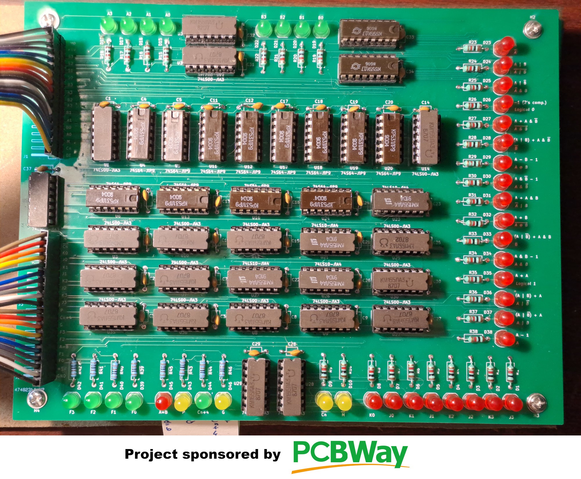
Here is a picture of the finished board:
![]()
The first stage is the set of 10 vertical chips in the upper half of the board. The second is the set of 20 horizontal chips below. All other components are only for display purposes and will not be included in the final version of the ALU board.
The Green LEDs on top are the two 4-bit inputs (A and B). The 16 red LEDs on the right indicate what function the ALU is currently executing, based on the S input. Only one of these LEDs is lit at a time. They are driven by a pair of К555ИД7s (=74x138) located right of the green input-display LEDs. At bottom, from left to right are located: the output display (4 green LEDs), various indicator signals and finally, 8 red LEDs showing the output of the first stage and input of the second. These signals play a central role in the operation of the ALU, as explained in Ken Schirriff's excellent blog post on the 74181.
The ONAN 1111 CPU will contain 5 boards equivalent to this one (5 slices of 4 bits = 20 bits wide). These final ALU boards will have a little more logic to handle shifting operations (which the 74181 does not do).
-
Testing the Soviet Chips
09/04/2022 at 12:15 • 1 commentBecause most soviet clone chips are new old stock (Over 30 years old in most cases), a little testing was in order. Therefore, I made the chip tester module below:
![]()
The Arduino Mega is a "generic" Chinese clone but it works all right. The last Zif socket (32 pins) is not yet installed because it is still in the mail. It should arrive shortly. I will have to test 32 pin chips when I start dealing with static RAM. I know this is not exactly "classic", according to my own definition, but I decided that using DRAM from the period (4164, 41256) would have really been too much of a hassle.
I am happy I made this tester because some batches of chips contained up to 25% duds.
If anyone is interested, I can publish the documentation for this tester here (Schematic, PCB and Arduino test programs).
-
Sourcing Soviet TTL Chips
09/04/2022 at 11:45 • 0 commentsThere are a number of good suppliers on ebay. Particular thanks to:
The Soviets copied the TI catalog of TTL 74xx chips from the 70s onwards. The oldest chips I have come across so far have date-codes from the early 80s. The following page has a very useful correspondence table between the Soviet model numbers and those of the 74xx series. With their Cyrillic markings and inimitably soviet-style plastic containers, these chips have an undeniable coolness factor to them. Here is a pictures of several of them:
![]()