 MichaelOmotosho
-
1Bill of Materials
PCB Design and Electronic Part List
- PCB Board Design
- Arduino, MKR WIFI 1010 - 176-3647
- Seeed Studio Air Quality Sensor v1.3 Grove System, Indoor Air Quality Testing
- MQ-7 Gas Sensor (Carbon Monoxide) × 1
- High Capacity Lithium-Ion Battery Pack (6700mAh) × 1
- JST PH 2-Pin Cable - Female to Female Connector 150mm × 2 ( If not available splice two females together)
- HARWIN M20, 2.54mm Pitch, 36 Way, 1 Row, Right Angle Pin Header, Through Hole
- RS PRO M3 x 6mm Hex Socket Cap Screw Plain Stainless Steel
- RS PRO, M3 Brass Threaded Insert diameter 4mm Depth 4.78mm
- RS PRO, Pozidrive Countersunk Stainless Steel Machine Screw M2 x 5mm
Tools
- Wires for PCB wiring (should come with the sensors)
- Double-sided adhesive tape
- Soldering Iron, Solder etc - to insert Brass Inserts
- Glue gun
- Scalpel Knives
- Tweezers
- Wire Cutters/Pliers
- Vernier Callipers
- Hand drill
- Dremel / Hand File
- Mini Hand Files - Flat, Round, Square (for metal, and plastic filing).
-
2Build and Assembly
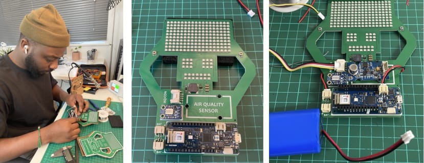
The build for this project has been a huge learning process for me, and as a Design Engineer, you would expect me to know a lot more, but that wasn’t the case. On this project, I learned how to solder for the first time (unbelievable, I know) and some other new discoveries.
Also as expected, I had some challenges with this project. Some of these were: a sensor not providing appropriate results, having to desolder the sensor and trying to make it right with a different sensor component, learning to code and also dealing with practical design issues for the Droid enclosure and fixtures.
This project was done in collaboration Rs Component Design Spark and also wouldn’t have been possible without the help and guidance of a Wiz friend, who is also a part of the DesignSpark and Hackaday Forum member Ahmed Oyenuga - Ahmsville. Please do check out his awesome projects and progress.
Components on PCB Board
I started by soldering the Arduino board to the PCB board, placing the pins through the holes and soldering on the PCB board rear and also did the same with the sensor using header pins. Being my first time soldering I had to ensure I got the right temperature to heat up the solder of about 350 degrees and also ensure I don’t have solder bridging across the pins.
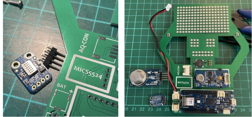
I had issues with the MICS5524 sensor not giving accurate results and that was the gas breakout sensor, which I haven’t added to the part list, although it's on the PCB board design. I have had to change it to an MQ-7 Gas Sensor which I am gave the desired carbon monoxide CO outdoor readings.
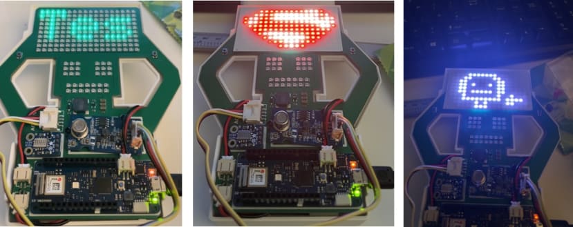
Once this was sorted the next phase was to test out the RGB addressable LEDs, soldered components and check for connectivity and check the sensors give appropriate results. Below are some the testing results for the Mindful Droid, where myself and Ahmed got a little bit excited with the testing.
-
3Mindful Droid Build Video
-
4The Code & Testing development
I wouldn't have been able to do this part without the guidance of Ahmsville and I'm super grateful for the support he provided on this project.
In addition to the animation and awareness word display feature on the droid, there are a few other functions like a noise buzzer when the pollution level is over a certain threshold, a clock display feature that can serve as a bedside night time table clock and a game function.
The features listed above are possible using Arduino MKR WIFI 1010 board, which has WiFi capability and is based on the ATSAD21 chip. The Droid has multiple features and runs various things at once, meaning I need to find a way to regulate the features and allow the user to have personal preferences in relation to what air quality they want to monitor or what matters most to their health and environment.
The program I wanted to run on this board would have to do a lot of different things at once. So, to assist in breaking it down into simple steps, I listed below the steps I carried out to ensure its main functions to possible wishes, as the codes evolves:
- Test are LEDs working on the PCB board.
- Design and Test Animations are working on display pixels
- Test air-quality sensors work by checking the serial monitor on Arduino
- Get the wifi + MQTT working on Droid
- Change the animations on the Droid based on sensor readings and values
- Get Droid animations into frames on Arduino
- Have the ESDK live values feed directly to the Droid animation
- Collect data, upload and store to cloud Grafana
The droid is driven by CO2 when indoors and CO when outdoors and also runs the VOC sensor supplied by Rs Component Design Spark.
int CO2thresh[4] = {500, 1000, 1500, 5000};
int VOCthresh[4] = {20, 50, 100, 150};
int COthresh[4] = {9, 35, 800, 12,800};
int GENERALAIRQUALITYthresh[4] = {65, 100, 150, 200};
At 400ppm CO2, the animation should have a cool happy smiley with glasses animation. At over 500ppm a normal occupied indoor space with good air exchange, there should be a green to amber or yellow smiley animation. At over 1200ppm, the user will be aware of the sad smiley face animation flickering from green to red, so the animation would get significantly frequent. At 1600ppm and over, the droid will increase attention to itself with an intermittent buzzer sound and changing animation to a sad crying face.
I also have a general air quality sensor on the droid that would be the default setting for when the droid is turned on. Using the buttons on both sides of the droid will help alternate through the AQ sensors and can also be programmed to change features and functions on the droid.
The code on the droid can be reprogrammed to something more specific or further equipped with more features and functions with respect to bringing awareness and change to air pollution.
Based on the demonstration video, it works nicely and shows an accurate result in relation to data collected from the ESDK (RS components Design Spark Kit) and also from the Droid itself.
Mindful Droid - Take Action against Air Pollution
Bringing awareness to air pollution and taking action by letting people know of the effects these poisonous gases emit from their vehicles
Discussions
Become a Hackaday.io Member
Create an account to leave a comment. Already have an account? Log In.