 Alpenglow Industries
-
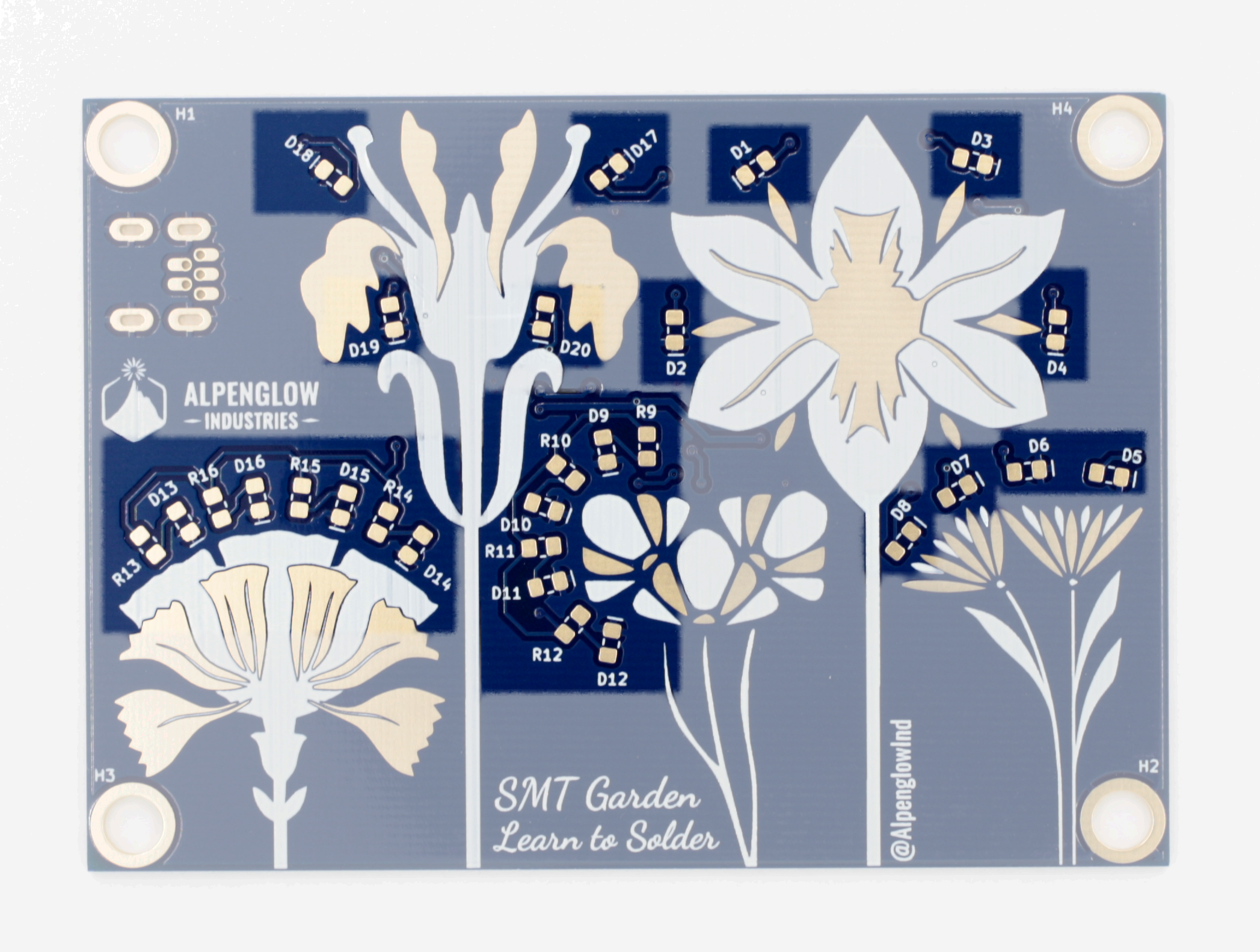
11Solder LEDs and remaining resistors on the front of the board
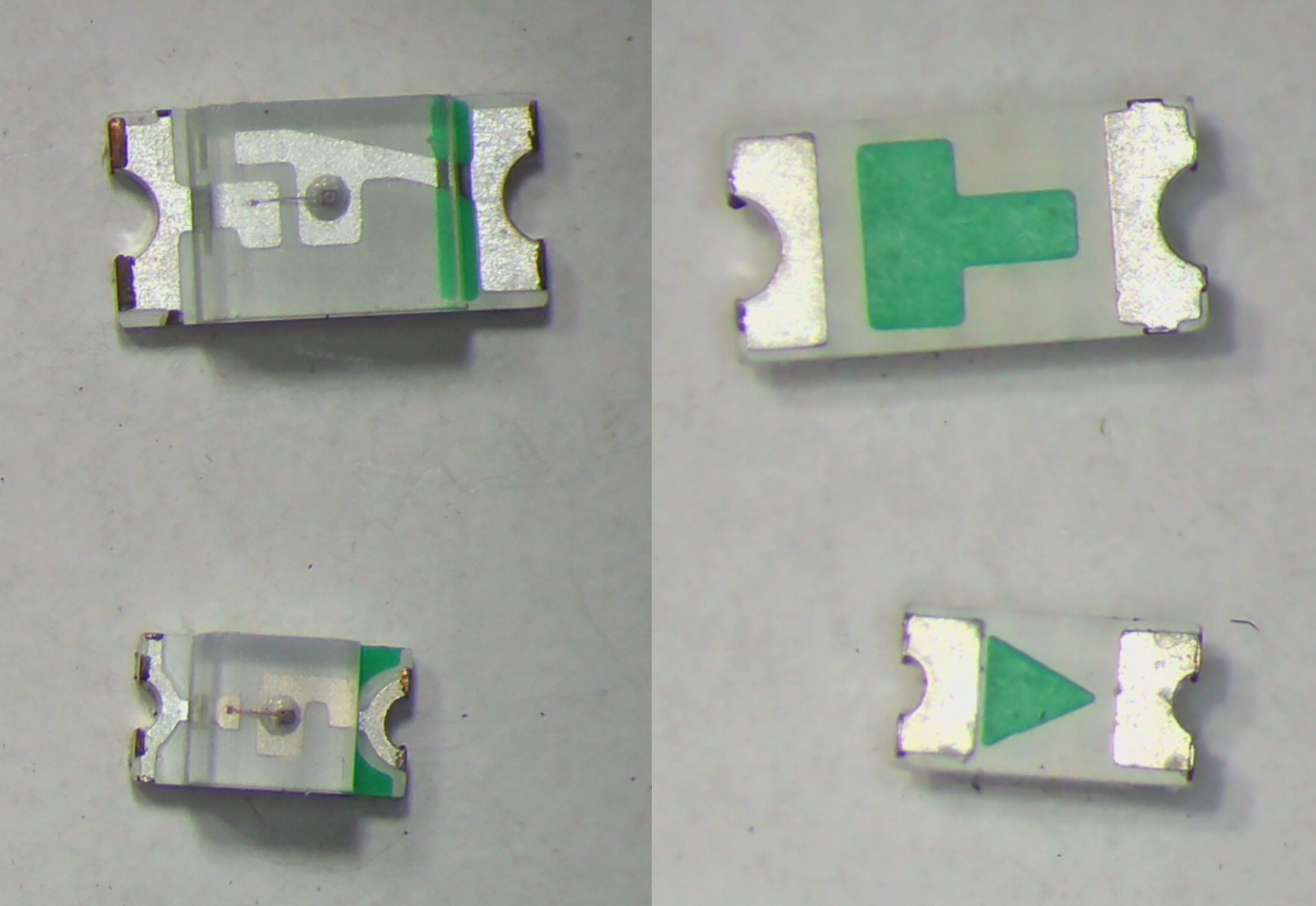
Note: LEDs are directional! Match the line on the footprint to the marking (usually a green dot or line) on the component. This will be the cathode. Many LEDs will also have a green arrow (sometimes very pixelated) on their underside, pointing to the cathode.
![]()
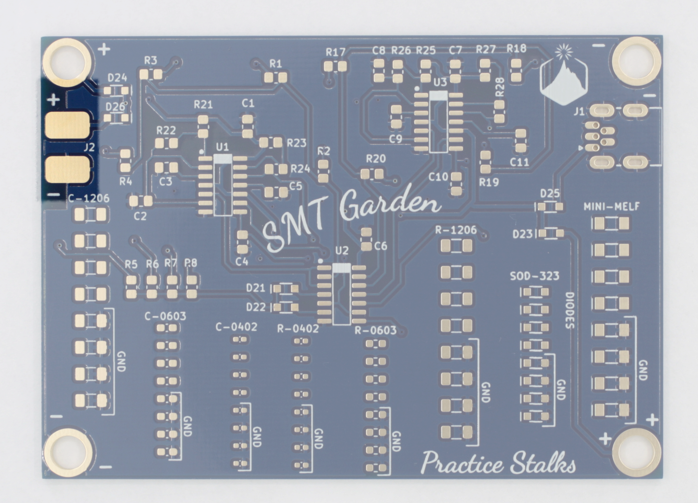
Resistors 1k ohm (R9-R16)
LEDs (D1-D20)![]()
![]()
-
12Plug into power or solder on battery holder
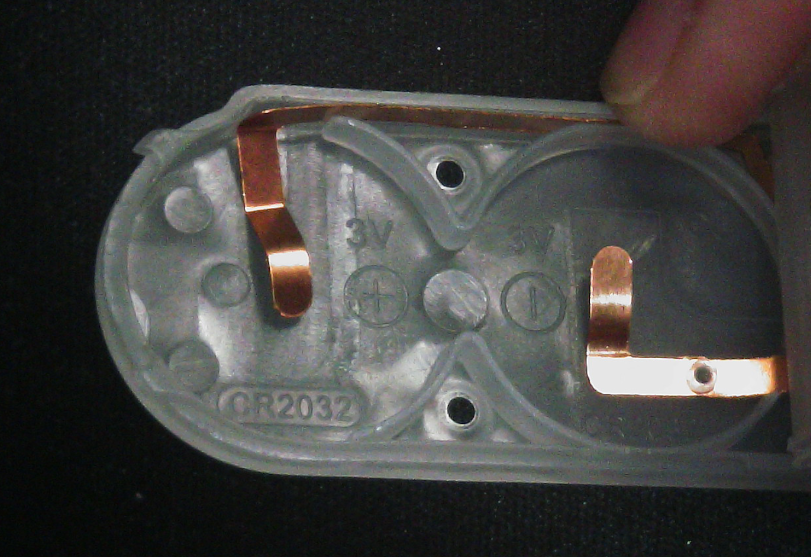
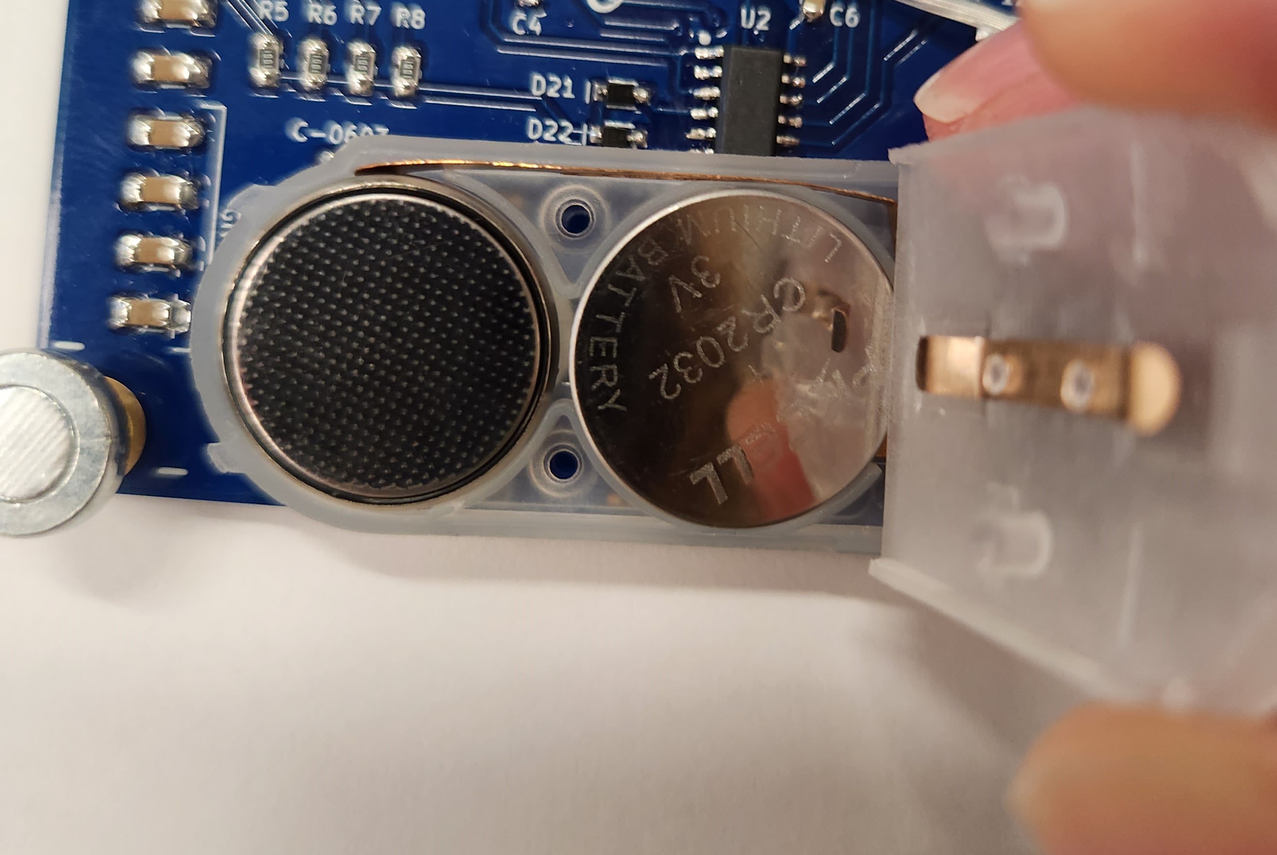
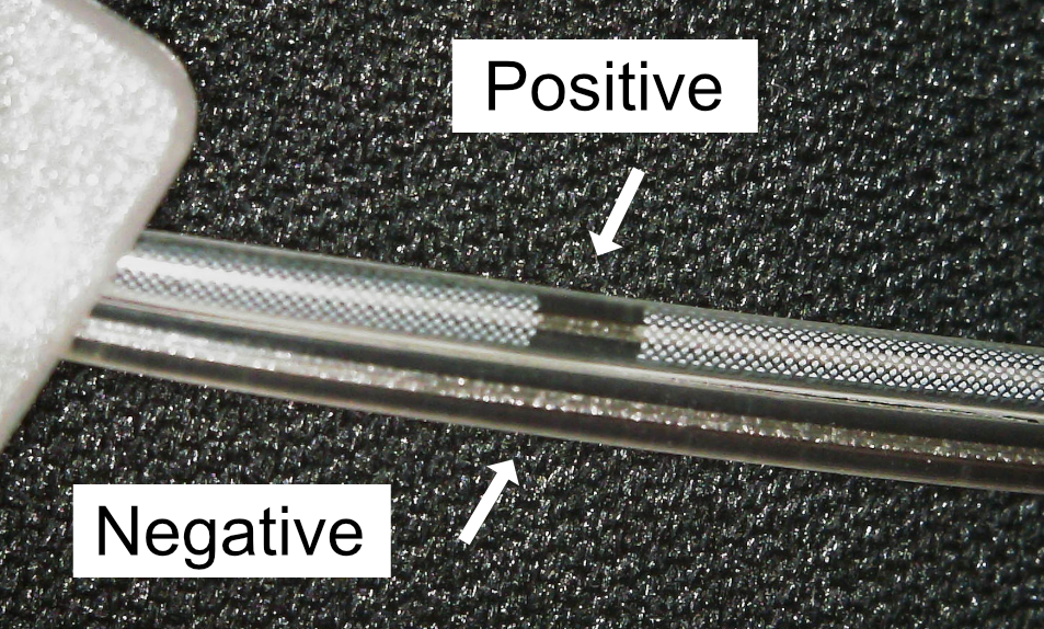
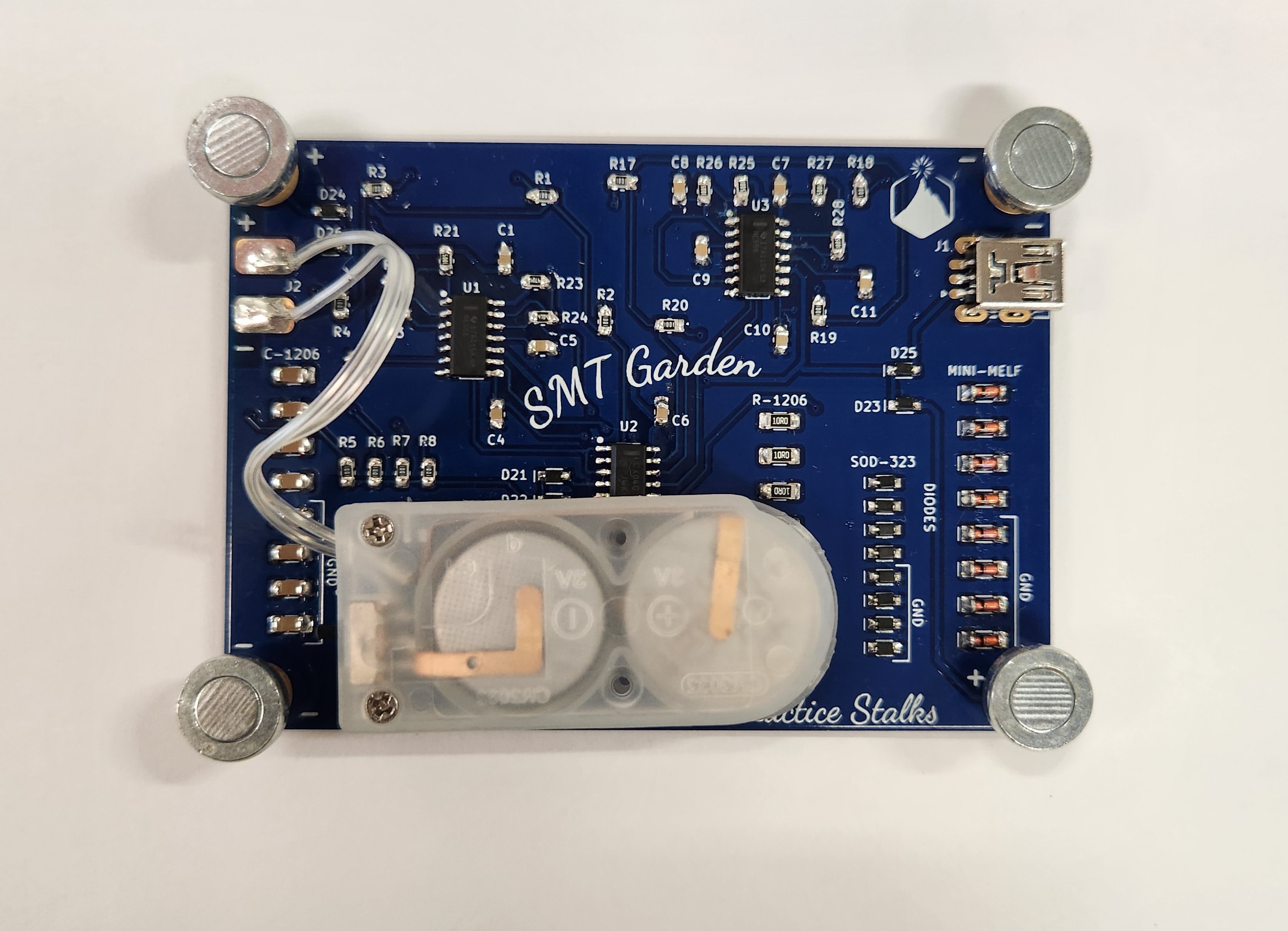
You can plug your board directly into a 5V USB outlet. Or you can power it off of two 3V coin cell batteries in series. Note that the batteries are inserted in opposite directions, and the marking on the bottom of the holder notes which side should be touching the bottom. See photos below.
![]()
![]()
The cable with the white markings and clear dash in it is positive (top in the photo). The unmarked cable is negative (bottom in the photo)
![]()
Line up where you want the battery holder to sit on the back of the PCB and cut the wires to length. Strip the ends and solder them to the pads matching positive to positive and negative to negative.
![]()
You can attach the battery holder to the back of the board with double-sided tape or adhesive dots. Or not - you might want to show off all those excellent joints!
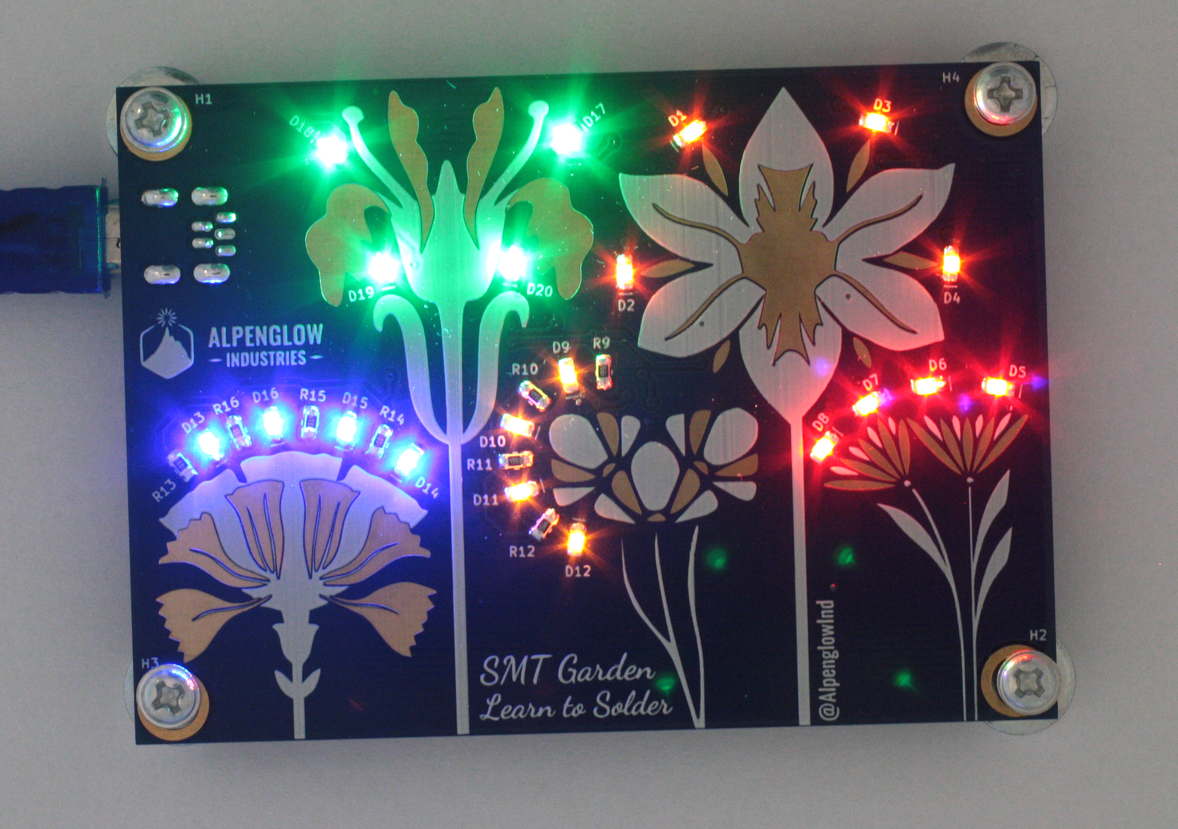
The battery holder has an on/off switch, to light up your board, switch it to on!
Enjoy the colorful flashing fruits ..er.. flowers of your labor!![]()
![]()
SMT Garden
Step by step instructions for our Learn to Surface Mount Solder board.

Discussions
Become a Hackaday.io Member
Create an account to leave a comment. Already have an account? Log In.